Note: Descriptions are shown in the official language in which they were submitted.
CA 02929827 2016-05-05
WO 2015/119694
PCT/US2014/065215
TURBINE COMPONENTS WITH NEGATIVE CTE FEATURES
BACKGROUND OF THE INVENTION
[0001] This invention relates generally to turbine components, and more
particularly to turbine components for use in high-temperature environments.
[0002] A typical gas turbine engine includes a turbomachinery core having a
high
pressure compressor, a combustor, and a high pressure turbine in serial flow
relationship. The core is operable in a known manner to generate a primary gas
flow.
The high pressure turbine includes one or more stages which extract energy
from the
primary gas flow. Each stage comprises a stationary turbine nozzle followed by
a
downstream rotor carrying turbine blades. These "hot section" components
operate in
an extremely high temperature environment which promotes hot corrosion and
oxidation of metal alloys.
[0003] In the prior art, hot section components are typically cast from
nickel- or
cobalt-based alloys having good high-temperature creep resistance, known
conventionally as "superalloys." These alloys are primarily designed to meet
mechanical property requirements such as creep rupture and fatigue strengths.
The
casting process is controlled to produce desired microstructures, for example
directionally solidified ("DS") or single-crystal ("SX"). A single-crystal
microstructure refers to a structure which is free from crystallographic grain
boundaries. Single crystal casting requires a seed element (that is, a
nucleation point
for cooling) and careful control of temperatures during cooling. However,
production
of such structures is expensive and has relatively low manufacturing yields.
[0004] Accordingly, there is a need for a gas turbine engine component
having
greater high-temperature creep and stress rupture resistance.
BRIEF DESCRIPTION OF THE INVENTION
[0005] This need is addressed by the present invention, which provides a
metallic
component incorporating a negative coefficient of thermal expansion ("CTE")
- 1 -
CA 02929827 2016-05-05
WO 2015/119694
PCT/US2014/065215
structure.
[0006] According to one aspect of the invention, a turbine component
includes: a
metallic wall having opposed interior and exterior surfaces, the wall
configured for
directing a combustion gas stream in a gas turbine engine; and a metallic
negative
CTE structure rigidly attached to one of the surfaces.
[0007] According to another aspect of the invention, the negative CTE
structure is
rigidly attached to the interior surface.
[0008] According to another aspect of the invention, the negative CTE
structure is
monolithically formed with the metallic wall.
[0009] According to another aspect of the invention, the metallic wall
forms part
of a gas turbine engine airfoil.
[0010] According to another aspect of the invention, the metallic wall is a
pressure side wall or suction side wall of the airfoil.
[0011] According to another aspect of the invention, the negative CTE
structure
comprises a repeating array of hexagonal cells.
[0012] According to another aspect of the invention, the negative CTE
structure
comprises a repeating two-dimensional array of generally hourglass-shaped
cells,
each cell having two spaced-apart concave walls joined by two spaced-apart
convex
walls.
[0013] According to another aspect of the invention, the negative CTE
structure
comprises a repeating two-dimensional array of cells having a square shape.
[0014] According to another aspect of the invention, the wall includes
opposed,
spaced-apart outer layers and a with a negative CTE structure filling the
space
between them.
[0015] According to another aspect of the invention, a method of making a
component includes: depositing a metallic powder on a workplane; directing a
beam
- 2 -
CA 02929827 2016-05-05
WO 2015/119694
PCT/US2014/065215
from a directed energy source to fuse the powder in a pattern corresponding to
a
cross-sectional layer of the component; repeating in a cycle the steps of
depositing
and fusing to build up a wall in a layer-by layer fashion, the wall having
opposed
interior and exterior surfaces, the wall configured for directing a combustion
gas
stream in a gas turbine engine; and having metallic negative CTE structure
monolithically formed with one of the surfaces.
[0016] According to another aspect of the invention, the negative CTE
structure is
monolithically formed with the interior surface.
[0017] According to another aspect of the invention, the wall is a pressure
side
wall or suction side wall of a gas turbine engine airfoil.
[0018] According to another aspect of the invention, the negative CTE
structure
comprises a repeating array of hexagonal cells.
[0019] According to another aspect of the invention, the negative CTE
structure
comprises a repeating two-dimensional array of generally hourglass-shaped
cells,
each cell having two spaced-apart concave walls joined by two spaced-apart
convex
walls.
[0020] According to another aspect of the invention, the negative CTE
structure
comprises a repeating two-dimensional array of cells having a square shape.
[0021] According to another aspect of the invention, the wall includes
opposed,
spaced-apart outer layers and a with a negative CTE structure filling the
space
between them.
BRIEF DESCRIPTION OF THE DRAWINGS
[0022] The invention may be best understood by reference to the following
description taken in conjunction with the accompanying drawing figures in
which:
[0023] FIG. 1 is a schematic perspective view of an exemplary turbine
component
constructed in accordance with an aspect of the present invention;
- 3 -
CA 02929827 2016-05-05
WO 2015/119694
PCT/US2014/065215
[0024] FIG. 2 is a schematic view of an exemplary negative CTE structure;
[0025] FIG. 3 is a schematic view of another exemplary negative CTE
structure;
[0026] FIG. 4 is a schematic view of another exemplary negative CTE
structure;
[0027] FIG. 5 is a schematic cross-sectional view of the turbine component
of
FIG. 1;
[0028] FIG. 6 is a view taken along lines 6-6 of FIG. 5;
[0029] FIG. 7 is partially-sectioned schematic side view of an additive
manufacturing apparatus constructed in accordance with an aspect of the
present
invention;
[0030] FIG. 8 is a view taken along lines 8-8 of FIG. 7;
[0031] FIG. 9 is partially-sectioned schematic side view of an additive
manufacturing apparatus constructed in accordance with an aspect of the
present
invention;
[0032] FIG. 10 is a view taken along lines 10-10 of FIG. 9;
[0033] FIG. 11 is partially-sectioned schematic side view of an additive
manufacturing apparatus constructed in accordance with an aspect of the
present
invention;
[0034] FIG. 12 is a view taken along lines 12-12 of FIG. 11;
[0035] FIG. 13 is a schematic plan view of a portion of a wall of a turbine
component; and
[0036] FIG. 14 is a view taken along lines 14-14 of FIG. 13.
DETAILED DESCRIPTION OF THE INVENTION
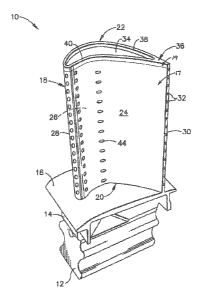
[0037] Referring to the drawings wherein identical reference numerals
denote the
same elements throughout the various views, FIG. 1 illustrates an exemplary
turbine
- 4 -
CA 02929827 2016-05-05
WO 2015/119694
PCT/US2014/065215
blade 10. The turbine blade 10 includes a conventional dovetail 12, which may
have
any suitable form including tangs that engage complementary tangs of a
dovetail slot
in a rotor disk (not shown) for radially retaining the blade 10 to the disk as
it rotates
during operation. A blade shank 14 extends radially upwardly from the dovetail
12
and terminates in a platform 16 that projects laterally outwardly from and
surrounds
the shank 14. A hollow airfoil 18 extends radially outwardly from the platform
16 and
into the hot gas stream. The airfoil has a root 20 at the junction of the
platform 16 and
the airfoil 18, and a tip 22 at its radially outer end. The airfoil 18 has a
concave
pressure side wall 24 and a convex suction side wall 26 joined together at a
leading
edge 28 and at a trailing edge 30. Collectively the pressure side wall 24 and
the
suction side wall 26 constitute a peripheral wall that encloses an interior
space, the
peripheral wall having an interior surface facing the interior space, and an
opposed
exterior surface facing the exterior environment. The airfoil 18 may take any
configuration suitable for extracting energy from the hot gas stream and
causing
rotation of the rotor disk. The airfoil 18 may incorporate a plurality of
trailing edge
cooling holes 32, or it may incorporate a number of trailing edge bleed slots
(not
shown) on the pressure side wall 24 of the airfoil 18. The tip 22 of the
airfoil 18 is
closed off by a tip cap 34 which may be integral to the airfoil 18 or
separately formed
and attached to the airfoil 18. An upstanding squealer tip 36 extends radially
outwardly from the tip cap 34 and is disposed in close proximity to a
stationary
shroud (not shown) in the assembled engine, in order to minimize airflow
losses past
the tip 22. The squealer tip 36 comprises a suction side tip wall 38 disposed
in a
spaced-apart relationship to a pressure side tip wall 40. The tip walls 40 and
38 are
integral to the airfoil 18 and form extensions of the pressure and suction
side walls 24
and 26, respectively. The outer surfaces of the pressure and suction side tip
walls 40
and 38 respectively form continuous surfaces with the outer surfaces of the
pressure
and suction side walls 24 and 26. A plurality of film cooling holes 44 pass
through the
exterior walls of the airfoil 18. The film cooling holes 44 communicate with
the
interior space of the airfoil 18. As seen in FIGS. 5 and 6, the interior of
the airfoil 18
may include a complex arrangement of cooling passageways defined by internal
walls
46, such as a serpentine configuration.
- 5 -
CA 02929827 2016-05-05
WO 2015/119694
PCT/US2014/065215
[0038] In order to have sufficient creep rupture and fatigue strengths, and
to resist
hot corrosion and oxidation, the turbine blade 10 is made from a material such
as a
nickel- or cobalt-based alloy having good high-temperature creep resistance,
known
conventionally as "superalloys." All materials, including such superalloys,
expand or
contract in response to a change in temperature. A material property called
coefficient
of thermal expansion or "CTE" relates the change in size (i.e. volume or
linear
dimension) of the material to the change in temperatures. Generally, CTE is
expressed
as av = 1/V (dV/dT) or UL = 1/L (dL/dT), respectively, where a represents the
CTE, V
volume, L length, and T temperature.
[0039] Most materials including superalloys have a positive CTE, meaning
that
their dimensions increase with increasing temperatures, when considered as a
homogenous mass, for example a rectangular solid. The positive CTE is a
contributing factor to growth by creep and potential component failure by
rupture.
[0040] Some structures exhibit a negative CTE as a result of their
geometry, even
though the constituent material has a positive CTE. In other words, the
dimensions of
the structure decrease with increasing temperatures. As used herein, the term
"negative CTE structure" refers to any structure that exhibits this property.
[0041] FIGS. 2-4 illustrate examples of several known structures which
exhibit a
negative CTE. FIG. 2 is a honeycomb structure comprising a repeating two-
dimensional array of cells 48, where each cell 48 is a regular hexagon defined
by
walls 63.
[0042] FIG. 3 is a pattern comprising a repeating two-dimensional array of
cells
50 which are generally hourglass-shaped, defined by a plurality of walls 52.
Each cell
50 has two walls 52 which are concave relative to that cell 50, joined by two
walls 52'
which are convex relative to that cell 50. Each cell 50 is rotated 90 degrees
relative to
its neighboring cells 50. As a result, each concave wall 52 of a first cell 50
also
defines a convex wall 52' of a neighboring cell 50.
[0043] FIG. 4 is a pattern comprising a repeating two-dimensional array of
cells
54 having a square shape.
- 6 -
CA 02929827 2016-05-05
WO 2015/119694
PCT/US2014/065215
[0044] The airfoil 18 incorporates a negative CTE structure to provide a
thermal
expansion offsetting effect. In the illustrated example, best seen in FIGS. 5
and 6, the
negative CTE structure comprises a pattern of hexagonal cells 48 as described
above,
formed integrally with the inner surfaces of the pressure and suction side
walls 24 and
26, respectively. The negative CTE structure may cover all or a selected
portion of the
airfoil peripheral wall. As illustrated, the negative CTE structure is
continuous, but
could be implemented in localized areas within the airfoil 18. The walls 63
defining
the cells 48 have a thickness or depth "Ti" which is a fraction of the total
thickness
"T2" of the airfoil peripheral wall. A greater thickness or depth Ti is
expected to have
a greater thermal expansion offsetting effect, while at the same time reducing
the
mass of the peripheral airfoil wall to a greater degree. Accordingly, the
exact
thickness fraction or ratio Ti/T2 will be selected depending on requirements
of a
specific application. In plan view (see FIG. 2), the cells 48 have a major
dimension or
diameter "D". This dimension, along with the thickness "W" of the walls 63,
will also
vary depending on the specific application.
[0045] It is noted that, solely considering the thermal expansion
offsetting effect,
the negative CTE structure could be disposed on the exterior surfaces of the
airfoil 18,
but for practical reasons such as maintaining the airfoil's aerodynamic
characteristics
and avoiding heat transfer to the airfoil 18, the negative CTE structure is
preferably
disposed on the interior surface of the airfoil peripheral wall.
[0046] The negative CTE structure defines a "scaffolding" which is rigidly
attached to the airfoil 18. The negative CTE structure may be a unitary, one
piece,
monolithic structure or element of the airfoil 18. The airfoil 18 operates in
a high-
temperature environment and is subject to creep and possible stress rupture,
driven by
thermal and mechanical loads, and the positive CTE of the base alloy. However,
contraction of the negative CTE structure in response to high temperatures
provides a
countervailing force offsetting the component growth. This also provides a
safety
margin against component rupture.
[0047] It is noted that the turbine blade 10 described above is only one
example of
numerous types of components, generally designated "C" herein, which can
- 7 -
CA 02929827 2016-05-05
WO 2015/119694
PCT/US2014/065215
incorporate a negative CTE structure. Nonlimiting examples of turbine
components to
which these principles apply include rotating airfoils (e.g. blades, buckets),
non-
rotating airfoils (e.g. turbine buckets, vanes), turbine shrouds, and
combustor
components. Each of these components has the common feature of a wall with
interior
and exterior surfaces, where the wall is configured for guiding or directing a
combustion gas stream during the operation of a gas turbine engine.
[0048] the negative CTE structure could also be incorporated directly into the
interior
structure of a component wall. For example, FIGS. 13 and 14 show a portion of
a wall
228, generally representative of a turbine component wall, such as the
pressure side
wall 24 or suction side wall 28 described above. The wall 228 includes
opposed,
spaced-apart outer layers 230 and 232, with a negative CTE structure 234
filling the
space between them.
[0049] Components C incorporating a negative CTE structure as described above
are
especially suited for production using an additive manufacturing method, as
the small-
scale internal structures may be difficult or impossible to manufacture using
conventional casting or machining processes. FIG. 7 illustrates schematically
an
apparatus 100 for carrying out an additive manufacturing method. The basic
components are a table 112, a powder supply 114, a scraper 116, an overflow
container 118, a build platform 120 optionally surrounded by a build enclosure
122, a
directed energy source 124, and a beam steering apparatus 126. Each of these
components will be described in more detail below. The apparatus 100 also
optionally
includes an external heat control apparatus which will be described below.
[0050] The table 112 is a rigid structure providing a planar worksurface
128. The
worksurface 128 is coplanar with and defines a virtual workplane. In the
illustrated
example it includes a central opening 130 communicating with the build
enclosure
122 and exposing the build platform 120, a supply opening 132 communicating
with
the powder supply 114, and an overflow opening 134 communicating with the
overflow container 118.
[0051] The scraper 116 is a rigid, laterally-elongated structure that lies
on the
- 8 -
CA 02929827 2016-05-05
WO 2015/119694
PCT/US2014/065215
worksurface 128. It is connected to an actuator 136 operable to selectively
move the
scraper 116 along the worksurface 128. The actuator 136 is depicted
schematically in
FIG. 7, with the understanding devices such as pneumatic or hydraulic
cylinders,
ballscrew or linear electric actuators, and so forth, may be used for this
purpose.
[0052] The powder supply 114 comprises a supply container 138 underlying
and
communicating with the supply opening, and an elevator 140. The elevator 140
is a
plate-like structure that is vertically slidable within the supply container
138. It is
connected to an actuator 142 operable to selectively move the elevator 140 up
or
down. The actuator 142 is depicted schematically in FIG. 7, with the
understanding
that devices such as pneumatic or hydraulic cylinders, ballscrew or linear
electric
actuators, and so forth, may be used for this purpose. When the elevator 140
is
lowered, a supply of metallic powder "P" of a desired alloy composition may be
loaded into the supply container 138. When the elevator 140 is raised, it
exposes the
powder P above the worksurface 128.
[0053] The build platform 120 is a plate-like structure that is vertically
slidable below
the central opening 130. It is connected to an actuator 121 operable to
selectively
move the build platform 120 up or down. The actuator 121 is depicted
schematically
in FIG. 7, with the understanding that devices such as pneumatic or hydraulic
cylinders, ballscrew or linear electric actuators, and so forth, may be used
for this
purpose.
[0054] The overflow container 118 underlies and communicates with the overflow
opening 134, and serves as a repository for excess powder P.
[0055] The directed energy source 124 may comprise any known device operable
to
generate a beam of suitable power and other operating characteristics to melt
and fuse
the metallic powder during the build process, described in more detail below.
For
example, the directed energy source 124 may be a laser having an output power
density having an order of magnitude of about 104 W/cm2. Other directed energy
sources such as electron beam guns are suitable alternatives to a laser.
[0056] The beam steering apparatus 126 comprises one or more mirrors, prisms,
- 9 -
CA 02929827 2016-05-05
WO 2015/119694
PCT/US2014/065215
and/or lenses and provided with suitable actuators, and arranged so that a
beam "B"
from the directed energy source 124 can be focused to a desired spot size and
steered
to a desired position in an X-Y plane coincident with the worksurface 128.
[0057] As used herein, the term "external heat control apparatus" refers to
apparatus other than the directed energy source 124 which is effective to
maintain a
component C positioned on the build platform 120 at an appropriate solutioning
temperature (i.e. to maintain a predetermined temperature profile) and
therefore
control the crystallographic properties of the solidifying powder P during the
build
process. As will be explained in more detail below, the external heat control
apparatus
may operate by acting directly as a source of heat (i.e. thermal energy input)
or by
retaining heat generated by the directed energy heating process.
[0058] Examples of various kinds of external heat control apparatus are
shown in
FIGS. 5-12. In FIGS. 7 and 8, a layer of thermal insulation 144 surrounds the
build
enclosure 122. The thermal insulation 144 is effective to impede heat transfer
from
the component C being built up, thereby reducing its cooling rate and
maintaining
elevated temperature.
[0059] FIGS. 9 and 10 illustrate an external heat control apparatus
including one
or more heaters. A belt-type electric resistance heater 146 is wrapped around
the
exterior of the build enclosure 122 and connected to an electric power source
148.
When active, the heater 146 heats the build enclosure 122 (and therefore the
component C inside) through thermal conduction.
[0060] Another optional type of external heat control apparatus is a radiation
heating
source. For example, FIG. 9 shows quartz lamps 150 (also referred to as quartz
halogen lamps) arranged with a line-of-sight to the component C and connected
to an
electric power source 152. Such lamps are commercially available, rated at
several
thousand watts output each. When active, the quartz lamps 150 heat the
component C
through radiation heat transfer. The quartz lamps 150 may be used instead of
or in
addition to the belt heater 146 described above.
[0061] Another option for the external heat control apparatus is inductive
heating, in
- 10 -
CA 02929827 2016-05-05
WO 2015/119694
PCT/US2014/065215
which an AC current flowing in an induction coil induces a magnetic field
which in
turn induces eddy currents in a nearby conductive object, resulting in
resistance
heating of the object. In the example shown in FIGS. 11 and 12, An induction
heater
154 includes one or more individual induction coils 156 surrounding the build
platform 120, connected to an electric power source 158. In the illustrated
example,
multiple induction coils 156 are provided. When active, the induction heater
154 is
effective to heat the component C. It has been demonstrated experimentally by
the
inventors that an external induction heating 154 of this type will
preferentially heat
the melted/solidified component C within a powder bed without heating the
loose
powder P sufficiently to cause it to melt or otherwise attach to the component
C being
built.
[0062] The build process for a component "C" using the apparatus described
above is as follows. The build platform 120 is moved to an initial high
position.
Optionally, a seed element 160 (see FIG. 2) may be first placed on the build
platform
120. The seed element 160 serves as a nucleation point for cooling and has a
selected
crystallographic structure. If it is desired to manufacture a single-crystal
component
C, the seed element will have a single-crystal microstructure. Such seed
elements 160
can be manufactured by known techniques. Once the seed element 160 is
positioned,
the build platform 120 is lowered below the worksurface 128 by a selected
layer
increment. The layer increment affects the speed and resolution of the
component C.
As an example, the layer increment may be about 10 to 50 micrometers (0.0003
to
0.002 in.). Powder "P" is then deposited over the build platform 120 and the
seed
element 160. For example, the elevator 140 of the supply container 138 may be
raised
to push powder through the supply opening 132, exposing it above the
worksurface
128. The scraper 116 is moved across the worksurface to spread the raised
powder P
horizontally over the build platform 120. Any excess powder P drops through
the
overflow opening 134 into the overflow container 118 as the scraper 116 passes
from
left to right. Subsequently, the scraper 116 may be retracted back to a
starting
position.
[0063] The directed energy source 124 is used to melt a two-dimensional
cross-
section of the component C being built. The directed energy source 124 emits a
beam
- 11 -
CA 02929827 2016-05-05
WO 2015/119694
PCT/US2014/065215
"B" and the beam steering apparatus 126 is used to steer or scan the focal
spot "S" of
the beam B over the exposed powder surface in an appropriate pattern. The
exposed
layer of the powder P is heated by the beam B to a temperature allowing it to
melt,
flow, and consolidate.
[0064] The build platform 120 is moved vertically downward by the layer
increment,
and another layer of powder P is applied in a similar thickness. The directed
energy
source 124 again emits a beam B and the beam steering apparatus 126 is used to
steer
or scan the focal spot S of the beam B over the exposed powder surface in an
appropriate pattern. The exposed layer of the powder P is heated by the beam B
to a
temperature allowing it to melt, flow, and consolidate both within the top
layer and
with the lower, previously-solidified layer.
[0065] This cycle of moving the build platform 120, applying powder P, and
then
directed energy melting the powder is repeated until the entire component C is
complete. The scan patterns used are selected such that the negative CTE
structure is
formed as an integral part of the component C.
[0066] The component C need not have a homogenous alloy composition. The
composition may be varied by changing the composition of the powder P during
the
additive manufacturing process, to produce varying layers or sections of the
component C. For example, the airfoil 18 shown in FIG. 1 may having a radially
inner
portion or body portion 17 (below the dashed line) with a first alloy
composition, and
a radially outer portion or tip portion 19 (above the dashed line) with a
second alloy
composition different from the first alloy.
[0067] If the component C is optionally formed with a single crystal
microstructure, this requires control of temperature and cooling rates
throughout the
component C during fabrication. The directed energy heat input from is
sufficient to
maintain required temperatures for the uppermost portion of the component C,
near
where new layers are actively being laid down, but not for its entire extent.
To address
this problem, the method of the present invention uses the external heat
control
apparatus during the cycle of powder deposition and directed energy melting.
- 12 -
CA 02929827 2016-05-05
WO 2015/119694
PCT/US2014/065215
[0068] The external heat control apparatus is operable to control both the
temperature and the heating rate of the entire component C. For example, one
known
solutioning heat treatment includes the steps of: (1) heating a component to
about
1260 C (2300 F) for about two hours to homogenize the microstructure, (2)
gradually
raising the temperature from about 1260 C (2300 F) to a solutioning
temperature of
about 1320 C (2415 F) at a rate of about 5.5 C (10 F) per hour, then (3)
maintaining
the component at that temperature for about two hours, followed by (4) cooling
to an
aging temperature of about 1120 C (2050 F) in three minutes or less.
[0069] Because the external heat control apparatus is separate from the
directed
energy source 124, it may also be used for other heat treatment processes,
such as
aging the component C after the build process is complete. For example, one
known
aging process involves primary aging the component at the aging temperature
for a
period of hours to achieve the desired microstructure.
[0070] The turbine components described herein have several advantages over
the
prior art. The negative CTE structure offsets component creep and provides a
margin
against stress rupture. The negative CTE structure could enable lesser alloys
to
perform in critical engine applications, possibly eliminating the need for
single crystal
materials. The negative CTE structure can also serve as part of the thermal
mechanical system to reduce the bulk temperature of the component heat
transfer. The
negative CTE structure can serve the function of turbulence promoters or
"turbulators" which are more dense than prior art cast turbulators for
improved heat
transfer. Likewise, if the negative CTE structure is contained within the
walls of the
outer and inner surfaces of an airfoil body, it can also serve as a heat
exchanger to
more efficiently cool the exterior walls.
[0071] The foregoing has described turbine components having a negative CTE
structure and a method for their manufacture. All of the features disclosed in
this
specification (including any accompanying claims, abstract and drawings),
and/or all
of the steps of any method or process so disclosed, may be combined in any
combination, except combinations where at least some of such features and/or
steps
are mutually exclusive.
- 13 -
CA 02929827 2016-05-05
WO 2015/119694
PCT/US2014/065215
[0072] Each feature disclosed in this specification (including any
accompanying
claims, abstract and drawings) may be replaced by alternative features serving
the
same, equivalent or similar purpose, unless expressly stated otherwise. Thus,
unless
expressly stated otherwise, each feature disclosed is one example only of a
generic
series of equivalent or similar features.
[0073] The invention is not restricted to the details of the foregoing
embodiment(s).
The invention extends any novel one, or any novel combination, of the features
disclosed in this specification (including any accompanying potential points
of
novelty, abstract and drawings), or to any novel one, or any novel
combination, of the
steps of any method or process so disclosed.
- 14 -