Note: Descriptions are shown in the official language in which they were submitted.
CA 02930260 2016-05-16
,
WORM SCREW FOR USE IN AN EXTRUDER AND EXTRUDER
The invention relates to a worm screw for use in an extruder and
to an extruder with such a worm screw.
In particular, the invention relates to a worm screw to be used
in a twin screw extruder and to a twin screw extruder.
In general, worm screws have a modular structure.
Therefore,
they can be adapted very flexibly to altered tasks and product
characteristics. The modular structure of a worm screw includes
a rod-shaped core, called mandrel or spindle, and individual
screw elements which are slid onto the spindle.
The elements
perform the classic functions of the screw during the extrusion
process, such as conveying, kneading, mixing or cutting of the
plastic material which is fed into and through the extruder.
For transmission of the high torque, the elements are in
positive engagement with the spindle and in addition braced
axially.
DE 10 2008 028 289 Al discloses a worm screw which at its end
face transfers the torque from segment to segment by means of
teeth.
DE 103 30 530 Al describes a shaft onto which a sleeve is
welded. Segments are threaded up to the stopping point. DE 10
2011 112 148 Al, DE 10 2004 042 846 B4 and DE 196 21 571 02 each
disclose special tooth gearings between the screw segments and
the spindle.
CA 02930260 2016-05-16
-2-
The task of the invention is to provide the state of the art
with an improvement or an alternative.
In a first aspect of the present invention, this task is solved
by a worm screw to be used in an extruder, the screw having a
spindle and a plurality of segments supported by the spindle and
arranged axially with respect to each other, with sealed segment
boundaries, a separate moment bridge being provided between each
first segment and each axially adjacent second segment of the
screw, which moment bridge is designed to transfer one moment
from the first to the second segment laterally to the spindle
over the segment boundary.
The terms are explained in more detail as follows:
The "segments" are those components of the screw which together
form the spiral or the plurality of spirals, respectively, for
plasticizing the plastic to be conveyed through the extruder in
cooperation with the extruder cylinder.
Every two axially adjacent segments abut axially against each
other at their segment boundaries, either directly, in the case
of directly adjacent segments, or indirectly, in the case of one
or more intermediary segments between them. The
slot forming
between them, in the simplest case an annulus, must be sealed
against the penetration of plastic melt towards the inside, i.e.
towards the spindle. For
this purpose, the segments are
normally braced axially. The
negative normal force causes
sufficient sealing due to surface pressure.
The "moment bridge" must cooperate both with the first segment
and with the second segment. If a moment acts on the screw, at
CA 02930260 2016-05-16
-3-
one particular segment, the first segment largely transfers the
moment to the moment bridge. The moment bridge then transfers
the moment to the axially adjacent second segment.
The moment bridge itself is neither integral with the first nor
with the second segment but a separate element of the composite
screw.
At the transition point from a first segment to a second
segment, the moment bridge can consist of several components or
of only one component.
It is explicitly pointed out, as a general rule, that within the
framework of the present patent application, indefinite articles
and mathematical terms such as "one", "two" etc., are to be
understood as minimum terms, i. e. as "at least one", "at least
two" etc., unless it is explicitly or implicitly included in the
context or obvious to the person skilled in the art that only
"exactly one", "exactly two" etc. is intended.
However, the worm screw according to the invention should have a
plurality of adjacent segments with a moment bridge. In
other
words, several segment boundaries between two axially adjacent
segments should be bridged by a moment bridge. It is
possible
for one bridge to transfer the moment from segment to segment
for a plurality of segment boundaries to be bridged; however, a
preferred embodiment provides for one moment bridge to transfer
only the moment of one segment boundary transition.
The moment transfer "laterally to the spindle" means that the
moment transfer takes place independently of the spindle, at
least for the most part, in particular for at least 90%. In
CA 02930260 2016-05-16
,
-4-
view of the force of gravity with which each segment acts on the
spindle anyway, causing friction, preferably the moment transfer
is taken off the spindle as far as possible and transferred to
the segments and the moment bridges(B8).
The transfer "laterally to" the spindle means preferably, but
not necessarily, that moment transfer takes place radially
outside the spindle.
Advantageously, the aspect of the invention described above
achieves torque transmission with the use of screw segments in
the area of extruders, i. e. single-screw extruders and twin-
screw extruders, with the stresses on the spindle known from the
state of the art, which can be very high and consist of torsion,
traction, pressure and flection, being reduced.
Therefore, the
risk of mechanical failure of the spindle is substantially
reduced as well.
In addition, less expensive shafts, ideally
smooth cylinders, can be used for the spindle, which in addition
increases availability of the shafts.
The moment bridge can be of a different material than the
segments.
For example, it is conceivable to design the moment bridges for
a different load than the segments.
Theoretically, the moment
bridges are almost exclusively subjected to shearing stresses so
that often materials with better mechanical properties can be
used than for the edges of the extruder windings on the
segments, which are subjected to many different types of
stresses.
In addition, the moment bridge can be made of a different
CA 02930260 2016-05-16
-5-
material than the spindle.
In this regard as well, the stresses to be expected can be
better alleviated in constructing the screw. In case
of an
ideal construction, the spindle would substantially have to bear
the axial tensile load created during bracing of the segments
for sealing the segment boundaries. In
addition, the spindle
will normally have to bear the bending moment caused by the own
weight of the segments and by its own weight as soon as the
extruder direction deviates from the vertical.
However, the
effects of own weight can normally be regarded as minor problems
in contrast with the bracing force.
If the moment bridge is arranged radially outside the spindle,
the geometry of the spindle can be simple.
Ideally, the spindle will have a circular cross-section within
the segments. The notch factor p will ideally be 1. The
more
circular and smooth the cross-section of the spindle, the larger
will the portion of the torque be which is transferred from
segment to neighboring segment via the moment bridge, and thus
laterally to the spindle, due to positive engagement.
This supports desired separation of the mechanical stresses, in
which it is the task of the screw segments themselves to
transfer the torsion stress via the moment bridges.
The moment bridge has - also preferably - a circular recess
facing the spindle so that between the moment bridge and the
spindle as well, the created catch effect is as little as
possible and thus moment transfer is also as little as possible.
CA 02930260 2016-05-16
-6-
The moment bridge has to engage in at least two segments.
The two segments connected by the moment bridge are, in the
simplest case in terms of construction, the segments axially
directly adjacent to the screw. However, alternatives are also
conceivable where a moment bridge transfers also or only the
moment from a first segment to a third or even farther away
segment, e. g. by means of recesses through a segment for one
moment bridge each or parts of a moment bridge.
In terms of construction, it is proposed for the moment bridge
to have the shape of a sleeve, with an axial extension and a
radial material thickness, where the axial extension is larger
than the radial material thickness many times over.
In particular, proportions are considered where the axial
extension is at least five times, preferably ten times, larger
than the radial material thickness, i. e. the simple thickness
of the sleeve wall. Both
the axial extension and the radial
material thickness are here determined as the arithmetic average
over the circumference.
A sleeve can easily be slid onto a cylindrical spindle and can
also be easily slid into a first segment, or a second segment
can easily be slid over it, respectively; so that between the
first segment and the moment bridge, and the moment bridge and
the second segment, one positive engagement each is created, at
the latest in case of a twist.
To keep the spirals in as fixed a position as possible, the
segments should preferably be tangentially fixed by the moment
bridge.
CA 02930260 2016-05-16
-7-
To create positive engagement between the moment bridge and the
segments, it is conceivable both for the moment bridge to have
axial teeth and for it to have radial teeth.
To avoid axial pressing of the moment bridge and achieve as
complete a separation of the various mechanical stresses as
possible, it is conceivable for the moment bridge to have axial
play between the segments.
For instance, a feather key can be inserted which in the
torsional direction acts as a carrier between the moment bridge
and a segment which has been slid on; the axial play ensuring
that the entire axial prestress affects exclusively the gaps
between the segments, but not the feather keys or the other
carriers.
Preferably, the moment bridge has a close axial sliding fit with
respect to the spindle, just like the segments preferably have a
close axial sliding fit with respect to the spindle and/or the
segments have a close axial sliding fit with respect to the
moment bridge. Tangentially, the moment bridge should be fixed
in relation to the spindle, i. e. it should not only have a
close sliding fit; in any case, however, the moment bridge
should be fixed in relation to the segments without slippage.
A "close sliding fit" is a fit defining a fixed seat, where
however the parts are not keyed in with each other. An
explanation concerning "close sliding fit" can be found e. g. in
Lueger, Otto:
"Lexikon der gesamten Technik und ihrer
Hilfswissenschaften, Band 7" Stuttgart, Leipzig 1909, page 47.
CA 02930260 2016-05-16
,
,
-8-
The "spindle" is to be understood to axially extend in any case
from the end of the first segment to the beginning of the last
segment. Introduction of the moment into the screw is possible
both via the spindle - in this case, tangential fixation between
the gear power take-off and the spindle is necessary - and via a
connection of the gear power take-off with at least one segment,
preferably the first segment in the axial direction, with the
connection transferring the moment.
To facilitate assembly, the moment bridge can be attached to a
segment so that it can be released in a nondestructive manner.
For instance, it is conceivable for the moment bridge to be
attached in a press fit or close sliding fit to the interior of
a segment.
When the screw is assembled, the segment simply
needs to be threaded onto the spindle together with the moment
bridge which has already been attached.
If several such
segments which all have an attached moment bridge on the same
side are threaded on in series, the screw is assembled
automatically.
Alternatively, the moment bridge can be separate from the two
segments which it connects.
In any case, the invention is to be regarded as implemented when
the segments, the spindle and the moment bridge are coordinated
such that at least 70% of a moment, in particular at least 80%,
are transferred from segment(s) to segment(s) via (a) moment
bridge(s); thus, maximally 30% are transmitted via the spindle,
in particular maximally 20%.
In prototype tests conducted by the inventors and in their model
calculations, however, substantially lower transmission rates
for the spindle have been found.
CA 02930260 2016-05-16
-9-
In particular, if the segments are freely rotatable around the
spindle, it is ensured simply by this fact that moments are
transmitted from them to the spindle only due to friction and
own weight.
It is clear that the advantages of a screw as described above
extend directly to an extruder, in particular a one-screw
extruder or a twin-screw extruder having a screw as described
above.
In the following, the invention will be described in more detail
by means of different embodiments with reference to the drawings
wherein:
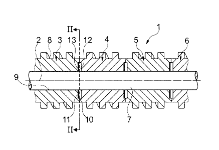
Figure 1 shows a simplifed longitudinal section of a first
embodiment of a screw with segments and moment bridges having
the form of catch plates on a spindle,
Figure 2 shows the screw from Fig. 1 along the line II-II,
Figure 3 shows a second embodiment of a screw according to the
invention in a representation analogous to Fig. 1,
Figure 4 shows the screw from Fig. 3 in cross-section along the
line IV-IV,
Figure 5 shows a top view of a coupling ring shown in Figs. 3
and 4 within the screw,
CA 02930260 2016-05-16
-10-
Figure 6 shows, in a third embodiment of the invention, a screw
having a sleeve with external toothing as a moment bridge,
Figure 7 shows the screw from Fig. 6 in a cross-section along
line VII-VII,
Figure 8 shows, in a fourth embodiment of the invention, a screw
having a fork-shaped sleeve as the moment bridge,
Figure 9 shows the fork-shaped sleeve from Fig. 8 alone,
Figure 10 shows, in a fifth embodiment of the invention, a screw
having a toothed ring with curved teeth as the moment bridge,
Figure 11 shows a schematic longitudinal section of a sixth
embodiment of a screw according to the invention, having
continuous bars as the moment bridge,
Figure 12 shows the screw from Figure 11 in a schematic cross-
section along line XII-XII in Figure 11, and
Figure 13 schematically shows a perspective view of a bar as
used in Figures 11 and 12.
The screw 1 in Figs. 1 and 2 consists, in the section visible in
the Figures, of screw segments axially adjacent and prestressed
against each other along a longitudial extension 2, i. e. a
first segment 3, a second segment 4, a third segment 5 and a
fourth segment 6. The
screw segments are threadingly pushed
against each other onto the spindle 7 in the longitudinal
CA 02930260 2016-05-16
-11-
extension 2.
Each screw segment has spirals 8 (numbered by way of example)
radially on the outside and an interior cylinder radially on the
inside, e. g. the first segment 3 over a first interior cylinder
9.
In addition, at an axial end face 10, the screw segments each
have exactly four disk-shaped recesses 11 (numbered by way of
example).
The disk-shaped recesses 11 of every two adjacent screw
segments, e. g. the first segment 3 and the second segment 4,
are flush, axially in front of each other and abut against each
other. They
contain four finger-shaped disks 12 (numbered by
way of example). The
finger-shaped disks 12 have an axial
extension which clearly exceeds an axial depth of the disk-
shaped recesses 11, but by less than 100%. In this
manner, the
axial end faces 10 of every two neighboring screw segments
securely rest against each other under prestress, thus sealing
the resultant screw 1 against plastic material flows from the
outside to the interior towards the spindle 7; at the same time,
however, the finger-shaped disks 12 are guided in recesses each
of which has an axial dimension of two disk-shaped recesses 11.
They are positioned there with an axial play 13 which is less
than the axial depth of the disk-shaped recesses 11 and less
than an axial extension of the finger-shaped disks 12.
Tangentially, the finger-shaped disks 12 rest inside the disk-
shaped recesses 11 in a close sliding fit so that tangentially
there is no play between the segments and the finger-shaped
disks 12, e. g. so that in a rotational movement, the first
segment 3 positively engages with the finger-shaped disks 12 and
CA 02930260 2016-05-16
,
-12-
the finger-shaped disks 12 positively engage with the second
segment 4, causing a rotational movement of the first segment 3
to be transferred without play to the axially adjacent second
segment 4.
During operation of the screw 1, the four finger-shaped disks 12
between the first segment 3 and the second segment 4 serve as
the moment bridge.
The moment bridge is the new constructive element proposed here
which is connected to at least two screw segments and whose task
it is to transmit the torque of one segment to the next.
Therefore, the torque is no longer transmitted via the spindle
7, as in the state of the art.
The spindle 7 remains free of
the torque stress; in the science concerning strength of
materials, one would speak of a separation between torsional
stress and direct stress.
Thus, the novel screw spindle has a
smaller diameter and can be completely smooth on the outside.
This increases permissible stresses in the area of the spindle
7.
Also, the basic material of the new constructive element,
i.e. of the moment bridge, can differ from that of the spindle.
Thus, the respective material can be better adapted to the tasks
to be solved:
the material of the new constructive element
(i.e. the moment bridge), can be mainly adapted for shearing
forces; the spindle material, in contrast, for flexural-type
stresses and axial forces.
One of the finger-shaped disks 12 could already serve as a
catch.
However, use of a plurality of separate parts, in the
present case four finger-shaped disks 12, as a catch between two
axially adjacent segments and thus as a moment bridge in the
sense of the present patent application, leads to a load
distribution and to a screw whose own weight has its center of
CA 02930260 2016-05-16
,
-13-
gravity in the longitudinal axis.
When the screw rotates, no
eccentric centrifugal forces and no eccentric weight loads will
occur.
With reference to Figs. 3 and 4, in the second embodiment of the
invention for an axially segmented screw 14, a first coupling
ring 15 (see specifically also Figs. 4 and 5) and a second
coupling ring 16 are used as moment bridges. Each coupling ring
15, 16 is cylindrical on the inside and therefore glides on the
spindle 7 without any substantial transmission of torque
(functionally equivalent or identical elements are sometimes
designated by the same reference numbers throughout the
figures). Therefore, here as well, the spindle 7 can be largely
free from the transmission of torques even during operation of
the screw 14, and merely subjected to tensile forces, which it
absorbs due to the fact that the screw segments are pressed
together axially for sealing and fixing the spirals.
The screw segments, here e. g. a first segment 17, a second
segment 18 and a third segment 19, are also formed cylindrical
towards their interior 20, however with an interior diameter 21
corresponding to an exterior diameter 22 of the coupling rings
15, 16 in their sleeve-like portions on both sides.
Therefore,
the segments 17, 18, 19 of the screw 14 can be slid onto the
sleeve-shaped portions 23 (indicated by way of example),
preferably in a close sliding fit.
The moment between the
coupling rings 15, 16 and the segments 17, 18, 19 is transferred
by means of radial protrusions 24 which engage in corresponding
radial recesses 25 (numbered by way of example) in the segments
17, 18, 19.
For creating a moment bridge, various other embodiments are
possible as well, e. g. the third embodiment of a screw 26 in
CA 02930260 2016-05-16
,
,
-14-
Figs. 6 and 7, which uses a sleeve 27 with outer teeth 28, which
also uses a ring-shaped slot 29 between the segments and the
spindle, but is furthermore provided with a second ring-shaped
slot 30 for leaving an axial play between the outer teeth 28 and
the material edges in the segments and thus for preventing
direct forces from affecting the outer teeth 28.
In the fourth embodiment of a screw 31, shown in Fig. 8, a fork-
shaped sleeve 32 (see Figs. 8 and 9) is used as the moment
bridge.
The fork-shaped sleeve 32 substantially corresponds to
two hubs which are mutually attached at their backs and have
continuous and cleared grooves 33 (numbered by way of example),
but which are preferably integral so that feather keys formed on
or attached to the segments can be slid into the grooves 33 and
so that here again, there is preferably no tangential play,
creating an immediate catch for torsional forces, whereas a play
should remain in the axial direction.
In the fifth embodiment of a screw 34 (see Fig. 10), an annular
gear 35 is provided as the moment bridge which has a plurality
of curved teeth 36 (numbered by way of example) and can be slid
on the spindle 7 in the longitudinal direction, with an open
ring-shaped slot 37, here again, existing between the segments
which are axially pressed onto each other, the longitudinal
axial extension of the ring-shaped slot being larger than the
longitudinal axial extension of the annular gear 35 so that no
axial forces are applied to the curved teeth 36 by the segments,
but so that a tangential engagement, without play, if possible,
is created between the curved teeth 36 and the neighboring
segments.
The screw in the sixth embodiment of the invention (Figures 11
and 12) again has a plurality of segments (three segments are
CA 02930260 2016-05-16
,
-15-
shown in Fig. 11) which are arranged on a spindle 38.
The
spindle 38 has a circular cross-section on the outer
circumference of which a circular inner circumference 39 of the
segments fits in close sliding fit.
On their inner circumference 39, the segments have evenly spaced
driving slots 40 (numbered by way of example) with a rectangular
cross-section.
The driving slots 40 of the segments are arranged flush with
each other. Through the flush driving slots 40, driving bars 41
(numbered by way of example, see also Fig. 13) are inserted.
Respective bars can be axially divided, or they can extend over
the entire segment length.
The driving bars 41 are made of a
material with high shearing strength, such as spring steel, so
as to be perfectly suited for the almost exclusive shear
stresses.
Generally, as a possible embodiment, the possibility of using
several feather keys should be mentioned which are distributed
over the circumference and can additionally be connected by a
ring.
The feather keys can also have different axial lengths
and/or be arranged mutually axially offset. Another embodiment
provides for several bushings which are slid onto the spindle.
On the outside of the bushings, grooves can be provided, for
example, which connect at least two segments by means of
additional feather keys.
However, the bushings can also have
springs, which would make additional feather keys unnecessary.
Here as well, at least two segments are interconnected.
In all conceivable embodiments, the springs or grooves can
either be narrow or alternatively have a large width.
The
advantage of large widths is that the number can be limited to a
CA 02930260 2016-05-16
,
-16-
few and that the function of torsion transfer is ensured.
Preferably, therefore, in an embodiment of the present
invention, a maximum of ten, preferably a maximum of eight, six,
four or two driving edges from a segment to the moment bridge
and preferably an identical number from the moment bridge to the
next neighboring segment are provided.
Briefly speaking, the invention is implemented if an additional
constructive element is provided between segment and spindle,
which element engages at least two segments, with the segments
radially overlapping the additional constructive element and
with at least 70%, in particular at least 80% or 90%, of the
torque being transferred from segment(s) to segment(s) via the
additional constructive element(s), i. e. at the most 30%, in
particular at the most 20% or 10%, are transferred via the
spindle.
In general, it should be pointed out that the moment is most
easily applied to the screw at the segment which is located
first as seen from the gear power take-off.
It is there that
the moment to be applied is largest because the largest
percentage by mass of the material to be conveyed is present in
the form of granules. The further the material proceeds through
the extruder, the larger the portion of molten granulate becomes
which leads to a reduction in resistance of the material against
screw rotation, and thus also to a reduction of the moment which
needs to be carried off.
CA 02930260 2016-05-16
-17-
List of reference numbers
1 screw
2 longitudinal extension
3 first segment
4 second segment
third segment
6 fourth segment
7 spindle
8 spiral
9 first inner cylinder
axial end face
11 disk-shaped recess
12 finger-shaped disk
13 axial play
14 screw
first coupling ring
16 second coupling ring
17 first segment
18 second segment
19 third segment
interior
21 inner diameter
22 outer diameter
23 sleeve-shaped portion
24 radial protrusion
radial recess
CA 02930260 2016-05-16
-18-
26 screw
27 sleeve
28 outer teeth
29 ring-shaped slot
30 second ring-shaped slot
31 screw
32 fork-shaped sleeve
33 groove
34 screw
35 annular gear
36 curved tooth
37 ring-shaped slot
38 circular spindle
39 inner circumference
40 driving slot
41 driving bar