Note: Descriptions are shown in the official language in which they were submitted.
CA 02930354 2016-05-11
WO 2015/079332 PCT/IB2014/064866
1
CATHETER CONNECTOR SECUREMENT DEVICE
FIELD OF THE INVENTION
The present invention relates generally to the field of medical catheters, and
more particularly to a securement device for a catheter connector.
BACKGROUND
The use of catheters to deliver or withdrawn fluids from a patient for various
medical procedures is well known. For example, U.S. Pat. No. 7,959,623
describes a pain management system that uses various embodiments of infusion
catheters to deliver fluid medication from a pump, through tubing, to a wound
site.
With such systems, catheter connectors are typically used to connect the
catheter
to various devices, such as tubing, a fluid reservoir or other fluid delivery
device,
and so forth. In the system of the '623 patent, a conventional Toughy Borst
connector is used to connect the distal end of a medical tube to the proximal
end
of the catheter.
In addition to Toughy Borst connectors, various other configurations of
catheter connectors are available. For example, Epimed International of
Farmers
Branch, TX, USA, manufactures a low profile twist-lock catheter connector
known
as the "Stingray 1M Connector." This device has axially aligned halves that
twist to
an open position to allow insertion of the catheter in a first half, and
subsequently
twist to a closed position with and audible and tactile click that indicates
complete
engagement with the catheter. The second half connects to a tube or other
fluid
delivery device for delivering fluid through the connector to the catheter.
Smiths Medical International Ltd. of the United Kingdom offers a catheter
connector under the "EpiFuse TM " tradename that consists of two halves joined
by a
living hinge. A catheter is inserted into a hole at the base of the connector
and is
retained when the two halves are folded and locked together.
Often, the use of such catheters and connectors must be maintained over
extended treatment time periods. It has been a well-known practice to secure
these devices with tape. However, the use of a tape dressing can be
problematic
in that, among other drawbacks, such dressings must be frequently changed,
CA 02930354 2016-05-11
WO 2015/079332 PCT/IB2014/064866
2
which can irritate the skin around the wound site and lead to build up of
adhesive
on the catheter devices. This adhesive can result in contaminates adhering to
the
devices, and can render the devices difficult to handle.
In this regard, devices have been developed to secure a catheter or
catheter connector to the patient without excessive use of tape. One such
device
is the ''Grip-Lok Tm" securement device from Zefon International Inc. of
Ocala, FL.,
USA. This device includes an adhesive base layer that attaches to the
patient's
skin. The catheter or catheter/connector combination is pressed onto an
adhesive
pad attached to an upper surface of the base layer. A Velcro TM closure layer
is
then folded over the catheter and attaches to the upper surface of the base
layer.
Another known catheter connector securement device is the "StatlockTM"
device from Bard Access Systems of Salt Lake City, Utah, USA. This device
includes an anterior anchor pad that attaches to the patient's skin. A "roll-
in, roll-
out" cage-like structure is attached to an upper surface of the anchor pad and
is
specifically designed for insertion and retention of a "SnapLockTM" catheter
connector (also from Bard Access Systems). A separate exit site pad includes a
device for securing and preventing migration of the catheter.
U.S. Patent No. 7,635,355 describes a device for securing a catheter
connector on the patient's body. The device includes an anchor pad that
attaches
to the patient's skin, with a retainer attached to an upper surface of the
pad. The
retainer has a base member and a cover hinged to the base member and movable
between an open and latch-closed position. The base and cover each have
respective grooves that cooperate to form a channel in the closed position of
the
cover. The connector has an elongated body that is received in the channel,
whereby axial motion of the connector is inhibited by engagement of the
connector
within the closed retainer.
The medical art is thus continuously seeking new and improved devices for
securing catheters and catheter/connector combinations relative to a patient
for
extended periods of time without discomfort to the patient, yet which allow
for
relatively easy release of the catheter or connector. The present invention
provides such a device.
CA 02930354 2016-05-11
WO 2015/079332 PCT/IB2014/064866
3
SUMMARY OF THE INVENTION
Objects and advantages of the invention will be set forth in part in the
following description, or may be obvious from the description, or may be
learned
through practice of the invention.
In certain aspects, the present invention relates to a catheter connector and
securement device system. A component of this system is a connector having a
body with a proximal end port configured for mating communication with a fluid
delivery device, such as a pump, reservoir, syringe, or the like. This port
may have
any conventional configuration, such as a Luer lock fitting. A passage is
defined in
the distal end of the connector body and is sized for sliding receipt of a
catheter
inserted therein. It should be appreciated that the system is not limited to
any
particular type, shape, or configuration of catheter connector, and that any
number
of conventional or commercially available connectors can be used in the
system.
The system also includes a securement device having a lower shell
member. This lower shell member includes a perimeter wall defining an interior
cradle space that conforms to the connector body, with the connector body
seated
within the cradle space such that the perimeter wall circumferentially engages
around the connector body. For example, if the connector has an oval body, the
cradle space has a conforming oval shape, and so forth. The perimeter wall has
a
proximal end groove defined therein, with the connector port extending axially
through the groove and beyond the perimeter wall for mating connection with
the
fluid delivery source. The perimeter wall extends continuously around a distal
end
of the connector body and has a slot defined therein that is axially aligned
with the
distal end passage of the connector body, wherein a catheter inserted into the
passage resides in the slot where it passes through the perimeter wall.
A cover member is hinged to the lower shell member at a hinge line and is
movable from an open position (for insertion and removal of the connector) to
a
closed position wherein the cover member releasably latches to the lower shell
member to retain the connector within the lower shell member.
In certain embodiments, the perimeter wall is a continuous circumferential
member that continuously engages around and against the connector body. The
port may also continuously engage against the proximal end groove.
CA 02930354 2016-05-11
WO 2015/079332 PCT/IB2014/064866
4
It should be appreciated that the cover member may be variously
configured. In one embodiment, the cover member has a distal end with a first
lip
that extends over the perimeter wall in the closed position of the cover
member.
This first lip has a slot defined therein that axially aligns with the slot in
the
perimeter wall so that the cover member can be closed over a catheter inserted
into the connector.
The cover member may include a second lip that also extends over the
perimeter wall in the closed position of the cover member, with the second lip
releasably latching into a latch slot extending outwardly from the perimeter
wall.
This second lip may be disposed opposite from the hinge line, with the cover
member having a proximal-most edge that extends between the hinge line and the
second lip such that a proximal portion of the perimeter wall and a proximal
portion
of the connector body are exposed and not covered by the cover member in the
closed position of the cover member. This configuration provides an exposed
edge that enables relatively easy manual manipulation of the cover member,
particularly when opening the cover member. With this configuration, the cover
member has a T-shape with points of contact with the perimeter wall at the
hinge
line, the first lip, and the second lip.
In an alternate embodiment, the cover member may have a continuous lip
that circumferentially extends from the catheter slot to the latch, such that
the
cover member has a generally half-clam shell configuration.
In certain embodiments, a bottom plate of the lower shell member includes
a catheter retention device spaced from the slot in the perimeter wall to hold
and
retain the catheter at a location spaced from the perimeter wall. This
retention
device may be any suitable mechanism for grasping the catheter without
pinching
off flow through the catheter. For example, the retention device may be an
upstanding biased arm that defines an undercut for receipt of the catheter
beneath
the arm.
Embodiments of the securement device may include an attachment pad
adhered or otherwise connected to the lower surface of the lower shell member,
with the attachment pad having an adhesive lower surface for attachment to a
patient's skin. This pad serves to position the system directly on the patient
at a
desired site, for example adjacent to a catheter entry site on the patient.
CA 02930354 2016-05-11
WO 2015/079332 PCT/IB2014/064866
The present invention also encompasses various embodiments of a
securement device for securing a catheter connector to a patient as a stand-
alone
component (e.g., without a connector seated within the cradle space). Various
embodiments of such a securement device are discussed above and set forth in
5 greater detail below.
BRIEF DESCRIPTION OF THE DRAWINGS
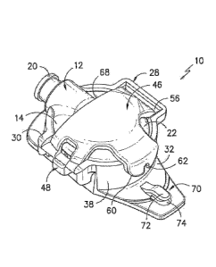
Fig. 1 is a perspective view of an exemplary catheter connector and
securement device system in accordance with aspects of the invention;
Fig. 2 is an alternate perspective view of the system of Fig. 1;
Fig. 3 is a perspective view of a conventional prior art catheter connector
that is used in the system of Figs. 1 and 2;
Fig. 4 is a perspective view of an embodiment of a securement device in
accordance with aspects of the invention;
Fig. 5 is a proximal end view of the system of Figs. 1 and 2;
Fig. 6 is a distal end view of the securement device of Fig. 4; and
Fig. 7 is a perspective view of the system of Fig. 2 with an attachment pad
and catheter.
DETAILED DESCRIPTION OF THE INVENTION
Reference will now be made in detail to one or more embodiments of the
invention, examples of the invention, examples of which are illustrated in the
drawings. Each example and embodiment is provided by way of explanation of the
invention, and is not meant as a limitation of the invention. For example,
features
illustrated or described as part of one embodiment may be used with another
embodiment to yield still a further embodiment. It is intended that the
invention
include these and other modifications and variations as coming within the
scope
and spirit of the invention.
The positional terms "proximal" and "distal" are used herein to orient the
various components relative to each other and to the patient. "Distal" refers
to the
direction that is closest to the wound site (e.g., the distal end of the
connector is
the end oriented towards a catheter insertion site), and "proximal" refers to
the
CA 02930354 2016-05-11
WO 2015/079332 PCT/IB2014/064866
6
opposite direction (e.g., the proximal end of the catheter is inserted into
the distal
end of the connector).
Figs. 1 and 2 are perspective views of an embodiment of a system 10 in
accordance with aspects of the invention. The system 10 includes a catheter
connector, generally 12, seated within a securement device 28. The particular
connector 12 illustrated in Figs. 1 and 2 is the prior art twist-lock
StingrayTm
connector from Epimed International depicted in Fig. 3 and discussed above in
the
Background section of the application. This particular connector 12 includes a
body 14 having a first half 16 and a second half 18. A proximal end port 20 is
configured with the second half 18 and may include any type of conventional
fitting
for mating communication with a fluid source, such as a syringe, tube;
reservoir,
pump, and the like. In the illustrated embodiment, the proximal end port 20
includes a conventional Luer lock fitting. The first half 16 of the connector
12
includes a distal end passage 24 having a size for sliding receipt of a
catheter 26
inserted therein, as particularly depicted in Fig. 3. As explained above, the
StingrayTM connector depicted in Fig. 3 is a twist-lock device wherein the
respective halves 16,18 twist to an open position to allow insertion of the
catheter
26 into the distal end passage 24. The halves 16; 18 subsequently twist back
into
an aligned configuration as depicted in Fig. 3 with an audible and tactile
click that
indicates complete engagement with the catheter 26.
It should be appreciated that the StingrayTm connector depicted in the
various figures is for illustrative purposes only. The system 10, and
particularly the
securement device 18, is not limited to the StingrayTm connector. Any
conventional
catheter connector may be utilized in the system 10 in accordance with aspects
of
the invention, with the securement device 28 configured for receipt of the
particular
type of connector, as explained in greater detail below.
Referring to the various figures in general, the securement device 28
includes a lower shell member 30. In the illustrated embodiment, the lower
shell
member 30 has a generally trapezoidal configuration. However, this is for
illustrative purposes only. The lower shell member 30 may have a rectangular,
oval, square, or any other type of overall shape and configuration. The lower
shell
member 30 includes a perimeter wall 38 that extends from a bottom surface or
plate 32, with the plate 32 having a lower surface 34. The perimeter wall 38
CA 02930354 2016-05-11
WO 2015/079332 PCT/IB2014/064866
7
defines an interior cradle space 40 designed to essentially correspond to the
outer
circumferential shape of the connector 12 seated within the cradle space 40,
as
can be appreciated particularly from Figs. 1 and 2. For example, in the
depicted
embodiment, the cradle space 40 has a generally circular configuration so as
to
conform to the circular shape of the StingrayTM connector 12 depicted in Fig.
3. If
the connector 12 were to have an oval or rectangular shape, then the cradle
space
40 would have a correspondingly shaped interior.
Referring to Figs. 1 and 2 in particular, the perimeter wall 38
circumferentially engages around the connector body 14 so as to form a
relatively
snug housing for the connector body 14. In the illustrated embodiment, the
perimeter wall 38 essentially engages completely around the connector body 14
in
that there are no spaces or gaps in the perimeter wall 38. In other
embodiments
not depicted in the figures, the perimeter wall 38 may have spaces or gaps so
long
as the connector body 14 is engaged around the circumference thereof at a
sufficient number of locations to define a snug cradle for the connector 12.
The perimeter wall 38 includes a proximal end groove 42 defined therein.
This groove 42 has a shape and depth so as to accommodate the proximal end
port 20 of the connector 12. In other words, the proximal end port 20 is
seated
within the proximal end groove 42 at the location where the port 20 extends
through the perimeter wall 38. As particularly seen in Figs. 5 and 6, the
groove 42
may engage essentially completely against the proximal end port 20 from one
end
of the groove to the other.
It should be appreciated that with the relatively snug cradle provided by the
cradle space 40 engaging against the connector body 14, as well as the groove
42
engaging against the proximal end port 20, the connector 12 is securely and
firmly
seated within the securement device 28 so that there is little or no relative
movement between the components.
At its distal end, the perimeter wall 38 may extend continuously around the
distal end of the connector body 14. A slot 44 is defined in the upper surface
of
the perimeter wall 38 at the distal end and axially aligns with the distal end
passage 24 in the connector body 14. In this manner, a catheter 26 inserted
into
the passage 24 resides in the slot 44 where the catheter 26 passes through the
CA 02930354 2016-05-11
WO 2015/079332
PCT/IB2014/064866
8
perimeter wall 38, as can be readily appreciated from the views of Fig. 6 and
Fig.
7.
Referring again to the figures in general, the securement device 28 includes
a cover member 46 that is hinged to the lower shell member 30 at a hinge line
48.
The cover member 46 is moveable from an open position depicted in Figs. 4 and
6
to the closed position depicted in Figs. 1, 2, and 5. In the open position,
the cradle
space 40 is accessible for insertion of the connector 12. In particular, the
body 14
of the connector 12 can be pressed into the cradle space 40 with the port 20
extending through the groove 42 and the distal end passage 24 aligned with the
slot 44. The cover member 46 is moveable to the closed position depicted in
Fig.
1 and latches to the lower shell member 30 by means of any suitable latch
device.
In the embodiment depicted in the figures, the latch device includes a latch
slot 56
defined in the lower shell member 30 that is engaged by an overhanging lip 64
on
the cover member 46. The lip 64 is biased and flexible to a degree necessary
for a
shoulder 66 on the lip 64 to slide through the slot 56, wherein the lip 64
flexes
outwardly and the shoulder 66 engages against the underside of the slot 56, as
can be appreciated from Figs. 5 and 6. It should be understood, however, that
any
suitable mechanical latch device may be used to secure the cover member 46
relative to the lower shell member 30.
Similarly, the system 10 is not limited to any particular hinge mechanism
between the cover member 46 and the lower shell member 30. In the embodiment
illustrated in the figures, the hinge line 48 is defined by a rod 50 on the
cover
member 46 that engages between flanges 52 formed on the lower shell member
30. The rod 50 is also seated within a biased support 54 that supports the rod
50
for rotation and ensures that the rod 50 is maintained engaged between the
flanges 52. Again, any suitable hinge mechanism may be used in this regard,
including a living hinge.
It should further be appreciated that the cover member 46 may be variously
configured within the scope and spirit of the invention. In the illustrated
embodiment, the cover member 46 has a distal end with an overhanging first lip
60
that extends over the perimeter wall 38 in the closed position of the cover
member
46, as particularly illustrated in Fig. 1. This lip 60 has a slot 62 defined
therein that
aligns with the slot 44 in the perimeter wall 38 in the closed position of the
cover
CA 02930354 2016-05-11
WO 2015/079332 PCT/IB2014/064866
9
member 46. With this configuration, the cover member 46 can be closed with a
catheter 26 inserted into the passage 24 in the connector body 14, with the
first lip
60 and slot 62 engaging around the catheter.
Referring particularly to Fig. 4, the latch lip 64 with the shoulder 66 may be
disposed directly opposite from the hinge line 48, with the cover member 46
having
a proximal-most edge 68 that extends between the hinge line 48 and second lip
64. With this configuration, as particularly seen in Fig. 2, a proximal
portion of the
connector body 14 and the perimeter wall 38 are exposed even when the cover
member 46 is in the closed position. This edge 68 provides a location for
relatively
easy manual manipulation of the cover member 46, particularly when opening the
cover member from the closed position. In the embodiment illustrated, the
cover
member 46 has a generally T-shaped configuration with points of contact with
the
perimeter wall 38 at the hinge line 48, the first lip 60, and the second lip
64.
In an alternate embodiment not depicted in the figures, the cover member
46 may have a continuous circumferential lip so as to engage essentially
completely around the perimeter wall 38. In this embodiment, a corresponding
groove would be defined in the continuous lip to conform over the proximal end
port 20 in the connector 12. Instill another embodiment, the cover member 46
may
have a generally half-clam shell configuration with a continuous lip.
Referring particular to Figs. 1, 2, and 7, certain embodiments of the
securement device 28 may include a catheter retention device 70 spaced from
the
perimeter wall 38. For example, this retention device 70 may be defined by a
flexible or biased projection or other arm-type structure 72 angled upwardly
and
away from the bottom plate 32 of the securement device 28. The projection 72
defines an undercut 74 having a height for frictional engagement with a
catheter 26
pressed under the projection 72. This catheter retention device 70 provides an
alternate location for securement of the catheter 26 relative to the
securement
device 28 and, thus, prevents inadvertent removal or pulling of the catheter
26
from the connector 12.
Referring to Fig. 7, an embodiment of the system 10 in accordance with
aspects of the invention may include an attachment pad 76, for example a foam
pad, for adhering the system 10 to a patient, for example directly to the
patient's
skin 75 adjacent to a catheter insertion site, This pad 76 may be made of any
CA 02930354 2016-05-11
WO 2015/079332
PCT/IB2014/064866
suitable material and may be adhered to the lower surface 34 of the bottom
plate
member 32. The bottom surface of the pad 74 may include any suitable medical
grade adhesive covered by a release layer, as is understood by those skilled
in the
art.
5 It
should be further appreciated that aspects of the present invention also
encompass various embodiments of the securement device 28 as a stand-alone
component (e.g., without a connector 12 seated within the cradle space 40 of
the
securement device 28). In this regard, the discussion set forth above of the
securement device 28 is relevant to the stand-alone securement device in
10 accordance with aspects of the invention.
While the present invention has been described in connection with certain
preferred embodiments it is to be understood that the subject matter
encompassed
by way of the present invention is not to be limited to those specific
embodiments.
On the contrary, it is intended for the subject matter of the invention to
include all
alternatives, modifications and equivalents as can be included within the
spirit and
scope of the following claims.