Note: Descriptions are shown in the official language in which they were submitted.
CA 02930430 2016-05-11
WO 2015/077603
PCT/US2014/066885
Microfluidic Methods and Systems for Isolating Particle
Clusters
TECHNICAL FIELD
The present disclosure relates to microfluidic methods and systems for
isolating particle clusters.
BACKGROUND
The presence of circulating tumor cell clusters and tumor-lymphocyte mixed
clusters is understood to be a potentially important factor in the prognosis
of a
metastatic process in patients. Isolation and retrieval of such cell clusters
therefore
may allow one to perform studies of disease progression and treatment response
of
cancers. Microfluidic technologies have emerged as indispensable tools for
isolating
and retrieving rare cells from whole blood for diagnosis and biomedical
research.
However, retrieval of trapped cell clusters on microfluidic chips can be a
challenging
task since methods for fixing the cell clusters in place may rely on the use
of antigen-
antibody reactions, which can alter the cell behavior. In addition, the cells
may
actively form specific/nonspecific bonds with varying strengths depending on
the
material constituting the microfluidic chip, the sample flow speed, and any
surface
coatings on the chip. In certain cases, these bonds are so strong that they
cannot be
broken with increased flow speed before causing lysis of the attached cells,
thus
necessitating the application of special surface coatings and chemicals to the
chip that
inevitably disturb the cell's natural state.
SUMMARY
The present disclosure relates to devices and methods for isolating clusters
of
particles, e.g., cells, from a fluid sample. In general, in a first aspect,
the subject
matter of the present disclosure can be embodied in microfluidic devices that
include
a substrate defining an inlet and an outlet; a set of structures arranged on
the substrate
between the inlet and the outlet to form multiple particle cluster capture
zones, in
which each particle cluster capture zone includes a subset of the structures
that
defines an input flow path that is divided, e.g., equally, into two output
flow paths by
a dividing barrier of one of the structures in the subset of the structures;
and multiple
1
CA 02930430 2016-05-11
WO 2015/077603
PCT/US2014/066885
microfluidic channels defined on the substrate to direct fluid from the inlet
to the
input flow paths of the particle cluster capture zones and from the output
flow paths
of the particle cluster capture zones to the outlet.
In general, in another aspect, the subject matter of this disclosure can be
embodied in techniques for minimizing non-specific binding of particles, such
as cell
clusters and cells, to walls of a microfluidic device by cooling the
microfluidic device
to relatively low temperatures, such as between 0 and 15 degrees Celsius,
during
operation of the device.
The microfluidic devices can include one or more of the following features.
For example, in some implementations, the subset of structures is further
arranged
such that each output flow path has a cross-section large enough to allow
passage of a
single particle of a first type and prohibit passage of a cluster of two or
more of the
particles of the first type. In some implementations, the structures are
arranged in two
or more rows, in which the structures in each row are laterally offset from
the
structures in an adjacent row to form the multiple particle cluster capture
zones. A
subset of structures can include three triangular prism structures arranged in
two rows,
in which first and second triangular prism structures are arranged in a first
row with
one corner of the first triangular prism structure being arranged adjacent to
one corner
of the second triangular prism structure to define the input flow path between
them,
and a third triangular prism structure is arranged in a second row offset from
the first
and second triangular prism structures in the first row, such that a sharp
edge of the
third triangular prism structure is arranged between adjacent corners of the
first and
second triangular prism structures located in the first row, and in which the
dividing
barrier is the sharp edge of the third triangular prism structure. The
particles may be
cells, the sharp edge of the third triangular prism structure can be
approximately
centered between the adjacent comers of the first and second triangular prism
structures, and a distance between each of the adjacent comers of the first
and second
triangular prism structures and the sharp edge of the third triangular prism
structure
can be at least 10 microns.
In some implementations, the dividing barrier has a corner radius less than
about 10 microns. In some implementations, the walls of the structure that
meet to
form the dividing barrier are at an angle less than or equal to 90 degrees.
2
CA 02930430 2016-05-11
WO 2015/077603
PCT/US2014/066885
In some implementations, all of the structures have a cross-sectional shape
that
is the same. In some implementations, the structures in the set of structures
include
two or more different cross-sectional shapes. In some implementations, one or
more
of the structures have a cross-sectional shape selected from the group
consisting of a
triangle, a diamond, a square, a rectangle, an ellipse, or a circle. In some
implementations, one or more of the structures have a shape selected from the
group
consisting of a triangular prism, a cube, a rectangular prism, a rombohedron,
a
circular cylinder, or an elliptic cylinder.
In some implementations, each structure has a height of at least 10 microns,
e.g., 20, 30, 40, 50, 60, 70, 80, 90, or 100 microns, or even more, e.g., 200,
or 300
microns.
In some implementations, the device includes a cooling device coupled to the
substrate, in which the cooling device is configured to cool the microfluidic
device to
a temperature between about 0 and 15 degrees Celsius.
In some implementations, the particles in the particle clusters include cells,
e.g., white blood cells, red blood cells, tumor cells, e.g., circulating tumor
cells
(CTCs), fetal cells, epithelial cells, or beads, e.g., magnetic or polymeric
beads, e.g.,
beads bound to cells.
In another aspect, the subject matter of the present disclosure can be
embodied
in methods of isolating particle clusters from a fluid sample using a
microfluidic
device, in which the methods include flowing, along a first direction, the
fluid sample
through multiple particle cluster capture zones in the microfluidic device, in
which
each particle cluster capture zone includes multiple structures arranged to
define an
input flow path that is divided equally into two output flow paths by a
dividing barrier
of one of the structures in the particle cluster capture zone, allowing a
particle cluster
from the fluid sample to be trapped at the dividing barrier in one of the
particle cluster
capture zones, and flowing, along a second direction that is opposite to the
first
direction, a second fluid through the plurality of particle cluster capture
zones to
release the trapped particle cluster.
The methods can include one or more of the following features. For example,
in some implementations, the particle clusters include cell clusters. The cell
clusters
may be circulating tumor cell (CTC) clusters.
3
CA 02930430 2016-05-11
WO 2015/077603
PCT/US2014/066885
In some implementations, the fluid sample further includes individual
particles, and the individual particles pass through the multiple particle
cluster capture
zones during flowing of the fluid sample without being trapped by the dividing
barriers of the particle capture zones. The individual particles may include
red blood
cells and/or white blood cells.
In some implementations, for each particle cluster capture zone, the two
outgoing fluid streams are separated by an angle of less than or equal to 90
degrees.
In some implementations, the method further includes cooling the microfluidic
device to a temperature between a freezing temperature of the fluid sample and
about
15 degrees Celsius.
In some implementations, the overall flow rate of the fluid sample through the
multiple particle cluster capture zones is less than about 250 ml/hr, e.g.,
200, 150,
100, 100, 50, or 25 ml/hr.
In some implementations, for each particle cluster capture zone, the flow rate
of the fluid sample through the particle cluster capture zone is less than
about 10
microliter/hr, e.g., 9, 8, 7, 6, 5, 4, 3, 2, or 1 microliter/hr.
In some implementations, for each particle cluster capture zone, the shear
flow
of the fluid sample through each of the outgoing fluid streams is less than
about 10,
20, 30, 40, or 50 s-1.
In some implementations, the particle cluster includes a cluster of two or
more
particles of a first type, and the subset of structures is further arranged
such that each
output flow path has a cross-section large enough to allow passage of a single
particle
of a first type and prohibit passage of the particle cluster.
For the purposes of this disclosure, a particle cluster is understood to mean
a
group of two or more particles held together, e.g., by chemical bonds (e.g.,
ionic
bonds, covalent bonds, Van der Waals forces, among others), magnetic forces,
and/or
electrostatic forces.
For the purposes of this disclosure, an individual particle is understood to
mean a particle that is not held together with other particles.
For the purposes of this disclosure, a dividing barrier is understood to mean
a
structure or portion, e.g., an edge, of a structure that is part of a particle
cluster
4
CA 02930430 2016-05-11
WO 2015/077603
PCT/US2014/066885
capture zone and is dimensioned and located to retain particle clusters. The
dividing
barrier is located in the particle cluster capture zone between two outlet
flow paths.
Implementations of the subject matter described herein can include several
advantages. For example, the devices described herein can be used to trap and
isolate
cell clusters without the need for antibody-antigen reactions. Accordingly,
cell
clusters may be studied without concern that such antibody-antigen reactions
will
alter the cell behavior. In addition, once trapped, the isolated cell clusters
can be
easily removed without the need to use high shear forces or other techniques
that may
disturb or damage the cell's natural state. Moreover, by reducing the
temperature of
the device, and thus the temperature of the fluid sample and particles within
the fluid
sample, relative to the ambient, the occurrence of non-specific binding can be
reduced, which may lead to an increase in purity of isolated cells or cell
clusters.
Unless otherwise defined, all technical and scientific terms used herein have
the same meaning as commonly understood by one of ordinary skill in the art to
which this invention belongs. Although methods and materials similar or
equivalent to
those described herein can be used in the practice or testing of the present
invention,
suitable methods and materials are described below. All publications, patent
applications, patents, and other references mentioned herein are incorporated
by
reference in their entirety. In case of conflict, the present specification,
including
definitions, will control. In addition, the materials, methods, and examples
are
illustrative only and not intended to be limiting.
Other features and advantages of the invention will be apparent from the
following detailed description, and from the claims.
BRIEF DESCRIPTION OF THE DRAWINGS
FIG lA is a schematic illustrating an example of a microfluidic device for
isolating particle clusters.
FIGS. 1B-1D are schematics illustrating three different phases of using a
microfluidic device to isolate particle clusters.
FIG. 2 is a schematic illustrating a top view of a particle cluster capture
zone
of a microfluidic device.
FIG 3 is a schematic illustrating forces acting on a particle cluster in a
particle
cluster capture zone and fluid speed in the particle cluster capture zone.
CA 02930430 2016-05-11
WO 2015/077603
PCT/US2014/066885
FIGS. 4A-4C are schematics that illustrate several examples of particle
cluster
capture zones in which the structures have different profiles.
FIG. 5 is a scanning electron microscope photograph of a microfluidic device
that includes triangular structures arranged in multiple particle cluster
capture zones.
FIG. 6 is a photograph of a microfluidic chip that is fabricated to include
multiple microfluidic channels that lead to different regions on the chip
having
particle cluster capture zones.
FIG 7 is a schematic that illustrates the concept of using a microfluidic
device
containing particle cluster capture zones with cooling to improve cluster
retrieval and
purity.
FIG. 8 is a plot that shows the rate of capture of clusters from a blood
sample
at different overall flow rates of the blood sample through a microfluidic
device
containing particle cluster capture zones.
FIG. 9 is a plot illustrating a percentage of patients found to have cancerous
cell clusters in their blood using a microfluidic device containing particle
cluster
capture zones.
FIG. 10 is a plot showing the release rate of cell clusters from particle
cluster
capture zones of a microfluidic device.
FIG. 11 is a schematic showing particle cluster capture zones of a device
after
passing a buffer solution through the device at room temperature and at 4
degrees
Celsius.
FIG 12 is a plot that shows cell viability for cells processed with the
microfluidic device having the particle cluster capture zones ("After
release") and for
cells that are not processed in the microfluidic device ("Before spike").
DETAILED DESCRIPTION
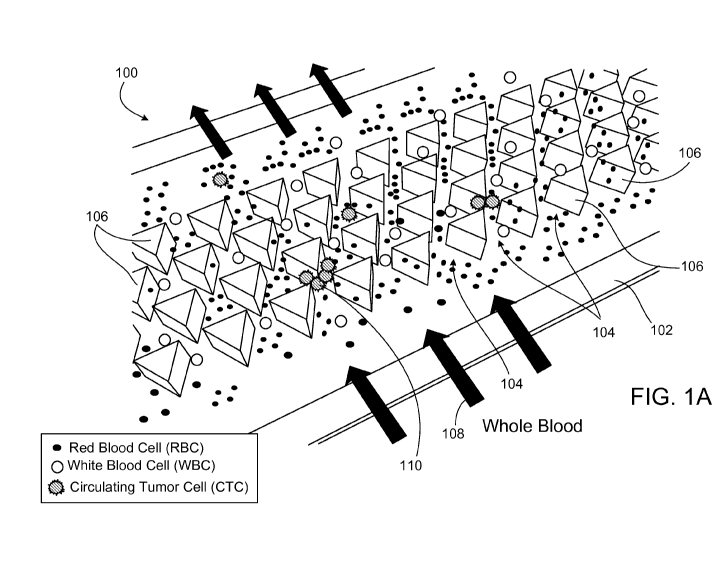
FIG. lA is a schematic that illustrates an example of a microfluidic device
100
capable of isolating particle clusters from a fluid sample. The device 100
includes a
substrate 102 on which are arranged multiple pillar-like structures 106. In
particular,
the pillar-like structures 106 are arranged to form multiple cluster capture
zones 104
on an uppermost surface of the substrate 102. During operation of the device
100, a
user introduces a fluid sample 108 (e.g., blood) containing one or more
particle
clusters 110 (e.g., circulating tumor cell clusters) into the device 100 such
that the
6
CA 02930430 2016-05-11
WO 2015/077603
PCT/US2014/066885
fluid sample flows through the particle cluster capture zones 104. Each
cluster
capture zone 104 within the capture area 102 includes a funnel portion that
directs an
incoming fluid stream of the fluid sample into two separate openings to form
two
outgoing fluid streams. The openings in each particle cluster capture zone 104
are
arranged about a dividing barrier of one of the pillar-like structures 106
within the
zone 104. As a particle cluster 110 in the fluid sample flows into a funnel
portion of
one of the particle cluster capture zones 104, the particle cluster may become
trapped
at the sharp-edge. The particle cluster is held in place on the dividing
barrier due to a
balance of forces including frictional forces and shear flow forces. However,
gaps
may remain in the openings of the particle cluster capture zones 104 that
allow
individual particles (i.e., particles that are not held together in a cluster
such as white
blood cells and/or red blood cells) to continue to pass through without being
trapped.
Thus, the multiple particle cluster capture zones 104 serve as a filter that
isolate
particle clusters from individual particles in a fluid sample. In some
implementations,
the structures that form the flow paths on either side of the dividing barrier
may be
arranged such that each of those flow paths has a cross-section large enough
to allow
passage of a single particle of a first type and prohibit passage of a cluster
of the
particles of the first type. After the fluid sample 108 passes through the
particle
cluster capture zones 104 and one or more particle clusters 110 are trapped,
the flow
of fluid through the device 100 can be reversed (using the same initial fluid
sample or
a different fluid) to release particle clusters trapped in the particle
cluster capture
zones 104.
FIGS. 1B-1D are a series of three schematics illustrating a top view of the
microfluidic device of FIG. lA at different stages of process for isolating
particle
clusters. In the first "cluster trapping" stage (FIG. 1B), the fluid sample
(e.g., blood)
containing the particle clusters 110 is introduced along a first direction to
the
structures 106 that are arranged in multiple particle cluster capture zones
104. One or
more particle clusters 110 are then trapped in the cluster particle capture
zones. After
flowing the fluid sample through the structures, the device 100 is washed with
a
second solution (e.g., a buffer solution) along the same direction as the
fluid sample
during a "washing" stage to clean out the fluid sample from the device 100
(see FIG.
1C). Subsequently, a third solution (e.g., another buffer solution) is passed
through
7
CA 02930430 2016-05-11
WO 2015/077603
PCT/US2014/066885
the structures 106 in the reverse direction to release the trapped particle
cluster 110
during a "release" stage (see FIG. 1D). The released particle clusters then
can be
collected for further study. In some implementations, the third stage that
includes
passing a solution in the reverse direction to release the trapped particle
clusters is
avoided, and the trapped particle clusters are studied in the capture device
itself
Alternatively, the purpose of isolating and trapping the particle clusters is
to remove
the particle clusters from the fluid sample in order to instead study the
individual
particles.
FIG. 2 is a top view of one of the cluster capture zones 104 of FIG. 1A. In
general, other particle capture zones in the device 100 have the same
arrangement as
shown in FIG. 2, and are positioned on an uppermost surface of the substrate
102 in a
repeated pattern. Thus, the particle cluster capture zone 104 contains a
subset of the
structures 106 in the device 100. In the present example, the particle cluster
capture
zone 104 includes three structures 106a, 106b, 106c, which define an input
flow path
200 that is divided into two output flow paths 202a, 202b. Two of the
structures
(106a, 106b) in the subset are arranged in a first row (e.g., at a top of the
cluster
capture zone 104) whereas a third structure 106c is arranged in a second row
adjacent
to the first row (e.g., at a bottom of the cluster capture zone 104). To form
each of the
particle cluster capture zones 104, the structures 106 of the device are
arranged in two
or more rows (see FIG. 1A), in which the structures in each subsequent row are
laterally offset from the structures in a preceding row.
The two structures 106a, 106b in the first row define a funnel region 206 that
directs the input flow path 200 and particles contained within the input flow
path 200
toward the output flow paths 202a, 202b. That is, the walls of the structures
106a,
106b are arranged such that a width of the input flow path 200 narrows from
the top
of the capture zone 104 towards the bottom structure 106c (i.e., one comer of
the first
triangular prism structure 106a is arranged adjacent to one corner of the
second
triangular prism structure 106b).
A spacing or gap between the top structures 106a and 106b is separated by a
dividing barrier 204 of the bottom structure 106c to form two separate
openings 206a,
206b. In general, the dividing barrier 204 is aligned substantially at the
center of a gap
between the top two structures 106a, 106b. Each opening leads to one of the
output
8
CA 02930430 2016-05-11
WO 2015/077603
PCT/US2014/066885
flow paths 202a, 202b. Thus, as the input flow path 200 travels toward the
dividing
barrier 204 of structure 106c, the flow path 200 is split about evenly between
the two
output flow paths 202a, 202b. As a particle cluster 250 travels along the
input flow
path 200, it will reach the dividing barrier 204 of structure 106c and become
trapped
due to a balance of frictional forces (e.g., arising from one or more of the
structures
106a, 106b, 106c) and shear flow forces (e.g., arising from the fluid flow) at
that
point.
FIG. 3 is a schematic that illustrates a top view of a portion of the particle
cluster capture zone on which arrows depicting the different forces that
affect a
particle cluster 350 are overlaid. Only half of each of the triangular prism
structures
106a, 106b in the top row of the zone is shown in FIG. 3, whereas the entire
triangular
prism structure 106c of the bottom row is shown in FIG. 3. In addition, the
regions
between the triangular structures are illustrated using a heat map to depict
examples
of how the fluid flow rate through the particle cluster capture zone varies
depending
on the location. In the present example, the flow rate varies from 0 to 60
p.m/sec,
though other ranges for the flow rate are also possible.
When a particle cluster 350 reaches the dividing barrier of the bottom
triangular prism structure 106c, the particle cluster 350 is trapped at the
dividing
barrier due to a dynamic balance of the forces shown in FIG. 3. These forces
include:
the frictional forces FF that arise due to the particle cluster 350 contacting
the sides of
the triangular structures 106a, 106b in the top row; the shear forces FD (also
called
drag forces) arising from the shear flow of fluid along the output flow paths;
and the
reaction forces FR due to the presence of the corners/walls of the triangular
prism
structures. Because the dividing barrier of the bottom triangular prism
structure is
approximately centered in the gap between the two adjacent top triangular
structures,
the shear forces FD experienced by the particle cluster 350 are balanced
between the
two output flow paths 202a, 202b (see FIG. 2). As a result, the particle
cluster 350 is
prevented from being diverted into one of the two openings. If, however, the
dividing
barrier were not centered in the gap, the shear flow experienced by the
particle cluster
350 would be greater along one or the other of the output flow paths, causing
the
particle to be directed into and possibly squeeze through the corresponding
opening.
9
CA 02930430 2016-05-11
WO 2015/077603
PCT/US2014/066885
In addition to the shear flow forces that balance the particle cluster 350 at
the
dividing barrier of the bottom triangular structure 106c, the frictional
forces FF from
the funnel walls restrict the movement of the particle cluster 350.
Furthermore,
contact between the funnel walls and the particle cluster 350 counter-balances
torque
or lateral motion the cluster 350 might experience if the particle cluster has
an
asymmetric shape. When the particle cluster 350 meets with the dividing
barrier of the
bottom structure 106c, the reaction forces FR due to one or more of the sharp
edges of
each of the structures in the capture zone 104 provide a countervailing force
against
the fluid shear forces. The reaction forces FR can balance the shear forces
when the
frictional forces alone are not large enough to keep the particle cluster 350
in dynamic
balance. The balance is considered "dynamic" because of the fluid actively
flowing
through the device.
Notably, an individual particle having a generally spherical shape will be
diverted to one or the other of the output flow paths 202a, 202b upon reaching
the
dividing barrier of the bottom triangular prism structure 106c. This is
because the
particle's rounded shape prevents it from obtaining a stable equilibrium, such
that it
rolls off the dividing barrier. In contrast, the different forces acting on a
particle
cluster may cause the interfaces between particles in the cluster to align
with the
dividing barrier, such that the particle cluster can remain in a stable
equilibrium.
An advantage of dynamically balancing the forces to trap particle clusters is
that the particle clusters can be released relatively easily. In particular,
if the particle
clusters were captured based solely due to friction forces, the same amount of
frictional forces would be needed to dislodge the particle cluster from its
trapped
position. However, when fluid flow is reversed (i.e., when fluid flows in the
opposite
direction to the input flow path), the reaction forces are absent. Thus, the
aggregate
force required to dislodge the trapped particle cluster is less than the
aggregate force
trapping the particle cluster under forward flow.
The heat map portion of FIG. 3 shows that variation in fluid flow speed
through the particle cluster capture zone. As the input flow path travels down
the
funnel to the bottom triangular prism structure 106c, the area within which
the fluid
can flow narrows. As a result, the fluid flow speed increases. As shown in the
example of FIG. 3, the region corresponding to maximum fluid flow speed within
the
CA 02930430 2016-05-11
WO 2015/077603
PCT/US2014/066885
particle cluster capture zone occurs in the area closest to where the corners
of each of
the triangular prism structures meet, i.e., where the fluid flow area is the
most narrow.
In contrast, the fluid flow speed decreases further away from the region where
the
corners meet, i.e., decreases where the fluid flow area is wider.
Though the structures 106 shown in FIGS. 1-3 have triangular prism shapes,
the structures 106 may have other shapes as well, so long as the portion of
the
structure to be used as the dividing barrier is relatively small (e.g., a
corner) compared
to the particle cluster to provide a reaction force that can balance the shear
forces
from the input fluid flow. For instance, in the case of circulating tumor
cells (CTCs),
which are about 5-25 microns, the dividing barrier should have a radius of
curvature
of about 1-2 microns, such that a cluster of CTCs has an average size along at
least
one dimension that is at least 2.5 times as great as the radius of curvature
of the
dividing barrier. Alternatively, or in addition, the walls of the structure
that meet to
form the dividing barrier may be at an angle of less than or equal to 90
degrees with
respect to each other. For example, in the case that an equilateral triangular
prism is
used as the structure, the walls that meet to form the dividing barrier would
be at an
angle of 60 degrees with respect to each other. In some implementations, the
dividing
barrier can even be a straight edge, so long as the length of the edge is
short relative to
the particle cluster being trapped. Accordingly, the term "dividing barrier"
as used
herein with respect to a structure does not necessarily mean the portion of
the
structure that comes to a fine point.
FIG. 4 is a schematic that illustrates several examples of particle cluster
capture zones in which the structures have different profiles (as seen from a
top view
of the device, i.e., the structure also have a thickness extending into the
page). The
structure can be a rombohedron shape (see FIG. 4A where the profile of the
structure
in the top view is diamond shape), such that the corner of the rombohedron
serves as
the dividing barrier on which a particle cluster can be balanced by the
friction, shear
and reaction forces. In some implementations, the structure can be a very
thin. For
example, FIG. 4B shows a particle cluster capture zone composed of structures
that
are thin rectangular prisms. The short side of the rectangular prism
structures may
have an edge that is between about 1 to 2 i.tm. FIG. 4C is an example of a
particle
cluster capture zone in which the structures have a circular profile. The
radius of
11
CA 02930430 2016-05-11
WO 2015/077603
PCT/US2014/066885
curvature of the circles is about 1-2 microns. In the example of FIG. 4C, the
dividing
barrier thus corresponds to the entire structure itself When a corner of a
structure is
used as the dividing barrier, the radius of curvature of the dividing barrier
is
preferably less than 10 microns including, for example, 5 microns, 2 microns,
1
micron, or 0.5 microns. Other radii of curvature may be used instead. In some
implementations, all of the structures within each particle cluster capture
zone, or all
of the structures within the microfluidic device that are used in the particle
cluster
capture zones have the same shape. Alternatively, the structures within a
particle
cluster capture zone may have different shapes. For example, some particle
cluster
capture zones may contain structures having triangular prism shapes, whereas
other
particle cluster capture zones may contain structures having rombohedron
shapes or
thin rectangular prism shapes.
In another example, the dividing barrier that forms a particle cluster capture
zone may be a first shape (e.g., a triangular prism) whereas the other two
structures of
the particle cluster capture zone may be a second, different shape (e.g., a
rectangular
prism, a rombohedron, or a cylinder). In some implementations, all of the
structures
within each particle cluster capture zone, or all of the structures within the
microfluidic device have the same shape and size. Alternatively, the
structures within
a particle cluster capture zone may have the same shape (e.g., cylinder,
rectangular
prism, triangular prism, rombohedron, cube) but different sizes (e.g.,
different
diameters, different volume, different cross-sectional area, different area as
determined along a plane that is parallel to or perpendicular to the direction
of fluid
sample flow). For example, each structure in a particle cluster capture zone
may be a
cylinder, but the diameter of the cylinder that corresponds to the dividing
barrier may
be smaller than the diameters of the other two structures within the particle
cluster
capture zone.
In some implementations, the microfluidic device can include additional
microfluidic channels that lead into and/or from the particle cluster capture
zones.
FIG. 5 is a scanning electron microscope photograph of a microfluidic device
that
includes triangular prism structures arranged in multiple particle cluster
capture
zones. The scale bar in the photograph represents 100 i.tm. As shown in FIG.
5, the
microfluidic device also includes a series of microfluidic channels fluidly
coupled to
12
CA 02930430 2016-05-11
WO 2015/077603
PCT/US2014/066885
the triangular structures. In particular, an inlet microfluidic channel 500 is
divided by
a first elongated barrier 502 into two additional microfluidic channels 504a,
504b that
feed into the triangular prism structures, which form the multiple particle
cluster
capture zones. Likewise, two microfluidic channels 506a, 506b at an output of
the
particle cluster capture zones merge together to around a second elongated
barrier 508
to form an outlet microfluidic channel 510.
To increase fluid throughput, multiple microfluidic channels and regions
containing particle cluster capture zones can be formed on the microfluidic
device.
For example, FIG. 6 is a photograph of an example of a microfluidic chip that
is
fabricated to include multiple microfluidic channels that lead to different
regions on
the chip having particle cluster capture zones. The fluid sample is fed into
the chip
using input tubing 600. The chip also includes multiple microfluidic channels
fluidly
coupled to the output of the particle cluster capture zones. The fluid is
removed from
the chip using an output tubing 602. The inset to FIG. 6 shows a close-up view
of
how microfluidic channels may be coupled to an area containing multiple
particle
cluster capture zones. Accordingly, by using a configuration such as the one
shown in
the example device of FIG.6, a greater amount of fluid sample may be filtered
using
the particle cluster capture zones.
The height/thickness of the structures in a particle cluster capture zone,
such
as structures 106 in FIG. 1, as measured from the uppermost surface of the
substrate
102 may be in the range of about 10 um to about 500 um including, for example,
about 501.11111, about 1001.11111, about 1501.11111, about 2001.11111, about
250 1.11111, about 300
um, about 350 um, about 4001.11111, or about 450 um. Other heights can be used
as
well. The surface area of the structures 106, as measured along a plane
parallel to the
uppermost surface of the substrate 102 may be in the range of about 78 um2 to
0.125
mm2 including, for example, about 200 um2, about 500 um2, about 1000 um2,
about
5000 um2, about 0.01 mm2, about 0.05 mm2, or about 0.1 mm2. Other areas can be
used as well.
Referring to FIG. 2, the widths of the openings 206a, 206b (as measured along
a plane normal to the flow paths 202a, 202b) in the particle capture zones 104
generally are about the same so as to ensure the shear forces, resulting from
flow
through paths 202a, 202b, are balanced on cluster particles trapped at the
dividing
13
CA 02930430 2016-05-11
WO 2015/077603
PCT/US2014/066885
barrier 204. The widths of the gaps may be set based on the size of the
separate
particles that form a particle cluster to be trapped. That is, the width may
be set to be
about equal to the diameter of one of the particles making up the cluster so
as to
inhibit clusters having two or more particles from flowing through one or more
of the
openings 206a, 206b. For instance, for a CTC particle cluster formed of CTC
cells
having an approximate diameter of about 12 mm, the width of each gap may be in
the
range of about 8 to 14 mm including, for example, 10 mm, 11 mm, 12 mm, or 13
mm.
Other widths can be used as well for other cell diameters. In some instances,
however,
the location of the dividing barrier 204 may off-centered in the gap, such
that the
widths of the openings 206a, 206b are different from one another. In such
cases, the
shear flow through the smaller opening will be less than the shear flow
through the
wider opening, and particle clusters may not be trapped due to an imbalance in
the
forces applied to the cluster.
The rate at which the sample fluid is passed through the particle cluster
capture zones is relatively slow compared to the rate that the washing fluid
is applied
in reverse to release trapped clusters. The slower flow rate is used for the
fluid
sample so that the shear forces on the particle clusters are not so high that
the forces
would push the clusters through the output flow paths of the particle cluster
capture
zones. For releasing the trapped particles, however, a much higher flow rate
is used
to wash away individual particles that may have become weakly bound to the
device
walls and to help release clusters that may also have become weakly bound to
the
device walls. For instance, the total volume flow of a fluid sample through a
device
containing particle cluster capture zones during a capture stage can be, e.g.,
in the
range of about 0.1 ml/hr to about 3 ml/hr, whereas the total volume flow of a
buffer
solution through the device when releasing trapped clusters can be, e.g., in
the range
of 20 ml/hr to about 250 ml/hr. Of course, the total volume through the device
can
also be increased or decreased based on the overall size and/or number of flow
paths
of the device. The rate at which fluid flows through each of the particle
cluster
capture zones is determined by dividing the total fluid flow rate by the
number of
particle cluster capture zones in the microfluidic device. For example,
assuming a
particular microfluidic device includes 4000 particle cluster capture zones,
and the
overall flow rate through the device is 2.5 ml/hr during the cluster trapping
stage, then
14
CA 02930430 2016-05-11
WO 2015/077603
PCT/US2014/066885
the average flow rate through each particle cluster capture zone is about
0.625 [tl/hr.
The flow rate of a fluid sample through particle cluster capture zones during
the
trapping stage can be in the range of, for example, about 0.11.11/hr to about
101.11/hr
including 0. 5 1.11/hr, 1 1.11/hr, 2 1.11/hr, 4 1.11/hr, 61.11/hr or 8 [tl/hr.
Other flow rates for the
fluid sample during the trapping stage are also possible. The flow rates of
the fluid
sample through the particle cluster capture zones also correspond to a shear
force.
For example, for each particle cluster capture zone, the shear flow of the
fluid sample
during the "capture" stage in each of the output flow paths may be less than
about 50
s-1 including, e.g., 40 s-1, 30 s-1, 20 s-1, 10 s-1, 10 s-1, or 0.5 s-1. Other
shear flow
values also may be used.
The particle clusters can include cells, such as CTCs, white blood cells, red
blood cells, white blood cell and CTC aggregates, circulating epithelial cells
(CECs),
plasma cells, megakaryocytes, progenitor cells, nuclieoli, heme (producing)
cells, or
sub-sets of heme (producing) cells. In the cases of CTCs, it is believed that
the cell
clusters are detached from the tumor tissue. In general, the cells in CTCs are
held
together by chemical bonds at their interfaces, where such bonds may form
during
tissue generation. In some implementations, the particle clusters include
beads, such
as polystyrene beads or magnetic beads. The beads may be conjugated with
antibodies so that they bind to analytes, such as cells, and/or to one
another.
Due to the relatively slow flow of fluid in the device, gravitational forces
can,
in some implementations, cause particles from the fluid sample to accumulate
near the
interface with the substrate, causing clogging of the device. To avoid such
clogging,
the device can be placed on its side so that the gravitational force is in the
direction of
the output of the microfluidic device, instead of toward the substrate.
Treating the Microfluidic Device to Inhibit Non-Specific Particle Binding
As explained above, microfluidic devices containing particle cluster capture
zones can be used to trap and subsequently isolate particle clusters from
fluid samples
without requiring the particle clusters to bind to a surface of the device. In
some
cases, however, other undesired particles bind, either specifically or non-
specifically,
to regions of the microfluidic device, thus lowering the purity of the
isolated particle
clusters. Alternatively, or in addition, the particle clusters themselves may
non-
CA 02930430 2016-05-11
WO 2015/077603
PCT/US2014/066885
specifically bind to portions of the microfluidic device, making it more
difficult to
release the trapped clusters upon passing a solution in the reverse direction
to the
direction of the initial fluid sample flow.
There are several techniques that can be used to avoid or inhibit this non-
specific binding. For example, one technique for limiting the amount of
undesired
binding of particles to a microfluidic device surface includes lowering the
temperature
of the solution and the particles contained within the solution. In the case
that the
particles within the fluid sample are cells, lower temperatures (relative to
ambient,
e.g., room temperature) lead to a reduction in cell-to-surface bond formation.
Accordingly, with fewer bonds being formed, fewer cells bind to the device
surface.
Thus, in a microfluidic device configured to trap and isolate a specific type
or types of
cells, the number of undesired cells that inadvertently bind to the device
surface can
be reduced, thus increasing isolation purity of desired cells.
The technique of cooling can be very effective in the microfluidic device
containing particle cluster capture zones. As explained herein, the particle
cluster
capture zones are configured to trap particle clusters mechanically, i.e.,
based on a
balance of mechanical forces. When the device is operated at room temperature,
a
cluster containing cells may actively form nonspecific bonds with the walls of
the
device. Therefore, when a solution is passed through the device to release the
trapped
clusters, a relatively large number of clusters may end up stuck to the device
surface.
However, when the device is operated at a temperature below ambient room
temperature, but above the freezing point of the fluid sample within the
device, the
number of particle clusters non-specifically binding to the device surface can
be
reduced, allowing a greater percentage of clusters to be retrieved from the
device. In
addition to an increase in cluster retrieval rate, the lower temperature can
also reduce
non-specific binding of individual cells to the device walls, enabling the
purity of the
retrieved clusters to be improved.
The temperature for reducing non-specific binding can be varied, but should
be above the freezing point of the solution in which the particles/cells are
contained
and below ambient room temperature. For instance, the temperature range can be
between about 0 degrees Celsius and 15 degrees Celsius including, e.g., a
temperature
16
CA 02930430 2016-05-11
WO 2015/077603
PCT/US2014/066885
of 2 C, 4 C, 6 C, 8 C, 10 C, 12 C, or 14 C. Other temperatures can be
used as
well.
FIG. 7 is a schematic that illustrates the concept of using a microfluidic
device
containing particle cluster capture zones with cooling to improve cluster
retrieval and
purity. As shown in FIG. 7, a fluid sample 702 such as whole blood at 25 C is
introduced to the microfluidic device 100 containing particle cluster capture
zones as
described herein. In the present example, the microfluidic device 100 is in
contact
with a thermoelectric cooling unit 704, although any applicable cooling
mechanism
may also be used. The cooling unit 704 cools the chip down to 4 C. Because of
the
device 100 is relatively thin, it is assumed that heat transfer processes
cause the fluid
and particles within the fluid also to cool down to the temperature of the
cooling unit,
i.e., about 4 C. During operation, the fluid sample then is passed through
the particle
cluster capture zone in a first stage (see "I-Capture" in FIG. 7). Then, a
phosphate
buffer solution (PBS) is passed through the particle cluster capture zone
along the
same direction as the fluid sample in a second stage (see "II-Washing" in FIG.
7).
Finally, a PBS is passed through the particle cluster capture zone in an
opposite
direction in a third stage (see "III-Release" in FIG. 7). During each stage,
the device
is maintained at the cooler temperature so that the binding of clusters and/or
individual particles is minimized.
The technique of cooling a microfluidic device to inhibit cell binding to the
device walls is not limited to the devices described herein. Instead, the
cooling
technique may be applied to other different microfluidic devices, where a
reduction in
cell binding, either non-specific or specific, is sought.
In addition, other techniques for reducing binding of cells and cell clusters
can
be used in addition to or as an alternative to cooling the microfluidic
device. For
example, in some cases, the surfaces of the device that are exposed to the
fluid sample
during device operation can be coated with a coating, e.g., a gel coating,
that reduces
cell binding. For example, gel coating techniques such as those discussed by
Shah et
al. in "Biopolymer System for Cell Recovery from Microfluidic Cell Capture
Devices," Analytical Chemistry, Volume 84, pp. 3682-3688 (2012), incorporated
herein by reference in its entirety, can be applied to surfaces of the
microfluidic
channels and cluster particle capture zones of the microfluidic device.
17
CA 02930430 2016-05-11
WO 2015/077603
PCT/US2014/066885
Other techniques include specific surface treatments that can be used to make
the surface of the inner walls of the structures in the particle cluster
capture zones
resistant to cell binding. Such techniques are known to those of skill in this
field.
Microfluidic Device Fabrication
As one example, the microfluidic device described herein (e.g., microfluidic
device 100) can be manufactured using the following soft lithography methods.
First,
a mold defining the features of the device 100 is obtained. For example, the
mold can
be formed by applying and sequentially patterning two layers of photoresist
(e.g.,
5U8, Microchem, Newton, MA) on a silicon wafer using two photolithography
masks
according to known methods. The masks can contain features that define the
different
aspects of the device 100 such as the input microfluidic channels, the
particle cluster
capture zones, and the output microfluidic channels. The wafer with the
patterned
photoresist then may be used as a master mold to form the microfluidic parts.
A
polymer (e.g., polydimethylsiloxane (PDMS), polymethylmethacrylate (PMMA), or
polycarbonate (PC)) solution then is applied to the master mold and cured
(e.g., by
heating). After curing, the polymer layer solidifies and can be peeled off the
master
mold. The solidified polymer layer includes recesses corresponding to the
fluid
channels and fluid pathways of the particle cluster capture zones. The polymer
layer
then is bonded to a substrate such as a glass slide. For example, a bottom
surface of
the polymer layer can be plasma treated to enhance the bonding properties of
the
polymer. The plasma treated polymer layer then may be placed on the glass
slide and
heated to induce bonding. After bonding the polymer to the glass slide, a
cover slide
(e.g., a glass slide) may be bonded to a top of the polymer layer to enclose
the
microfluidic channels and particle cluster capture zones. The surface of the
polymer
layer contacting the cover slide may also be plasma treated before bonding to
the
cover.
The example of a microfluidic device 100 described above, includes a
substrate layer of glass, a polymer layer defining the microfluidic channels
and the
particle cluster capture zones, and a cover layer made of glass. In other
implementations, the substrate layer and/or the cover layer can be polymer
substrates
or other similar materials.
18
CA 02930430 2016-05-11
WO 2015/077603
PCT/US2014/066885
The foregoing technique is just one example of a fabrication method for the
microfluidic device. Other techniques may be used instead. For example,
techniques
such as hot embossing, LIGA, or injection molding may be used to fabricate one
or
more layers of the microfluidic device including the particle cluster capture
zones.
Microfluidics
In some implementations, the microfluidic channels and/or particle cluster
capture zones of the microfluidic devices described herein are part of a
larger,
optional, microfluidic channel network. Such microfluidic networks can be used
to
facilitate control and manipulation (e.g., separation, segregation) of small
volumes of
liquid and help isolate target analytes from a complex parent specimen. During
the
isolation process, microfluidic elements provide vital functions, for example,
handling
of biological fluids or reproducible mixing of magnetic particles with
samples.
Additional information about microfluidic channel networks and their
fabrication can
be found, for example, in U.S. Patent App. Publication No. 2011/0091987, U.S.
Patent No. 8,021,614, and 8,186,913, each of which is incorporated herein by
reference in its entirety.
Applications
There is an ever increasing need in biological research, for example, for more
accurate and efficient methods to manipulate and separate target particle and
cell
populations. Disciplines ranging from immunology and cancer medicine to stem
cell
biology are highly dependent on the identification of uncontaminated
populations of
particular particle and cell subsets for detailed characterization.
Clinically,
microbiologists routinely isolate bacterial cells and white blood cell subsets
for
diagnostic purposes. Tumor antigen-specific regulatory T cells can be
discovered in
the circulating blood of cancer patients, presenting a new potential target
for
immunotherapy of metastatic melanoma. Environmental sensing requires
surveillance
of water, food and beverage processing for specific bacterial cell
contamination.
Vaccine developers work largely with antigen-specific T lymphocytes, rare
cells
which may differ from one another by no more than a single amino acid in a
peptide
fragment presented on the cell surface. In these different applications a
common
19
CA 02930430 2016-05-11
WO 2015/077603
PCT/US2014/066885
problem is presented: the need to isolate, separate and characterize
subpopulations of
cells present within heterogeneous, complex fluids. During the processing of
these
samples, the target cell population must be handled with gentle care,
preventing
alteration of the cell's physiological state to allow for subsequent
expression profiling
and molecular studies. Moreover, the cells of interest may be present at
extremely low
frequencies-often less than 1 cell in 10,000,000 cells, for circulating tumor
cells or
disease-specific T lymphocytes, increasing the complexity of the challenge.
The devices containing particle cluster capture zones described herein can be
used as a means of isolating cell clusters found in fluid samples for the
above-
mentioned research and analysis. For example, in some implementations, a blood
sample extracted from a patient may or may not contain a number of clusters of
circulating tumor cells (CTCs), which can be indicative of the occurrence of
cancer
metastasis in the patient. A user interested in identifying the presence of
the CTC
clusters can use the microfluidic device to isolate CTC clusters present in
the blood
sample from individual cells (e.g., individual white blood cells or individual
red blood
cells) that are not part of a cluster. Once the cell clusters have been
isolated, a user
may then perform an analysis on the isolated clusters (e.g., count the number
of CTC
clusters present in the blood sample to diagnose the patient, to study disease
progression, or to study the response of the patient to a treatment). The
devices
described herein are not limited to uses involving isolation of CTC clusters
and can be
used in a wide range of applications requiring enumerating, sorting,
concentrating and
ordering of particle clusters or removing undesired particle clusters from
fluid
samples.
The systems and methods described herein thus provide a manner in which
rare cells, such as CTC clusters, can be sorted, separated, enumerated, and
analyzed
continuously and at high rates. Whether a particular cell cluster is a rare
cell cluster
can be viewed in at least two different ways. In a first manner of
characterizing a cell
cluster as rare, the rare cell cluster can be said to be any cell that does
not naturally
occur as a significant fraction of a given sample. For example, for human or
manlillalian blood, a rare cell cluster may be any cell cluster other than a
subject's
normal blood cell (such as a non-cancerous red blood cell and a non-cancerous
white
blood cell). In this view, cancer or other cells present in the blood would be
CA 02930430 2016-05-11
WO 2015/077603
PCT/US2014/066885
considered rare cells. In a second manner of characterizing a cell cluster as
rare might
take into account the frequency with which that cell cluster appears in a
sample. For
example, a rare cell cluster may be a cell cluster that appears at a frequency
of
approximately 1 to 50 cells per ml of blood. Alternatively, rare cell cluster
frequency
within a given population containing non-rare cells can include, but is not
limited to,
frequencies of less than about 1 cell cluster in 100 cells; 1 cell cluster in
1,000 cells; 1
cell cluster in 10,000 cells; 1 cell cluster in 100,000 cells; 1 cell cluster
in 1,000,000
cells; 1 cell cluster in 10,000,000 cells; 1 cell cluster in 100,000,000
cells; or 1 cell
cluster in 1,000,000,000 cells.
EXAMPLES
The invention is further described in the following examples, which do not
limit the scope of the invention described in the claims.
The experiments to obtain the data discussed in the following examples were
performed as follows. First, a mold of the microfluidic channels and particle
cluster
capture zones was fabricated by first etching the channel and capture zone
design into
a silicon master using soft-lithography with SU-8 and a mask. Uncured PDMS was
then poured onto the mold and cured at 65 C for about 8 hours. The PDMS
containing the outline of the channels then was bonded to a glass substrate.
For each
device, the PDMS was treated with 02 plasma prior to bonding to the substrate.
A
cover glass was bonded to a surface of the PDMS layer. The cover layer
included
openings that could be fluidly coupled to inlet microfluidic channels and
outlet
microfluidic channels, respectively. Inlet and outlet tubes were then coupled
to the
openings in the cover layer.
Two types of experiments were performed: spiked cell experiments to
characterize the device performance and identification of CTC clusters in
patient
samples. In spiked cell experiments, cancer cell lines such as LNCaP, H1650,
MDA-
MB-213 cell lines were used to create artificial cell clusters. These
artificial clusters
were stained with cell tracker fluorescent probes and were spiked into whole
blood
obtained from healthy donors. The spiked blood was then processed using the
chip.
In experiments that required the precise control of the flow rate (e.g., to
determine the
effect of flow rate on the CTC cluster capture rate), syringe pumps were used
that
21
CA 02930430 2016-05-11
WO 2015/077603
PCT/US2014/066885
could precisely control the volumetric flow rate. In other spiked cell
experiments,
constant pressure sources were used where the flow rate control was not
critical. After
the spiked blood was processed, the chip was washed with phosphate buffer
solution
at 2.5 ml/hr for 1 hour. Then, the imaging and counting of the cells was
performed
using a fluorescence microscope to characterize the chip.
In experiments for identifying CTC Clusters from patient samples, blood was
collected from patients using ethylenediaminetetraacetic acid (EDTA) anti-
coagulant
tubes. For these experiments, constant pressure sources were used and set at
0.43 psi.
This pressure gave roughly 2.5 ml/hr volumetric flow rate but changed with
blood
hematocrit/ viscosity. The blood sample was continuously rocked to prevent
blood
settling and coagulation. The blood was processed using the microfluidic chip
and
then washed with phosphate buffer solution at 2.5 ml/hr for 1 hour. For
performing
immune-staining, the cells were first fixed in 4% paraformaldehyde (PFA), and
then
stained for nucleus, white blood cells and CTCs using a cocktail antibody
stain. Then,
the fluorescence microscope was used to image stained CTC clusters. When cells
were to be released from the chip, the solution flow was reversed by switching
the
inlet and outlet tubings. For release experiments, the device was operated on
a
thermoelectric cooler to increase the efficiency of CTC Cluster release
process. In
some of the release experiments, the cells were stained for surface tumor
markers on
the chip before releasing them so that the CTC clusters could be easily
identified.
Example 1 ¨ Cluster Capture Rate
FIG. 8 is a plot that shows the rate of capture of CTC clusters from a blood
sample at different overall flow rates of the blood sample through a
microfluidic
device containing particle cluster capture zones. As shown in FIG. 8, as the
overall
flow rate of the fluid sample was increased through the device, the capture
efficiency
of the cell clusters by the device decreased, especially for smaller sized
clusters (i.e.,
clusters containing less cells). This is because the shear forces experienced
by the
cluster are much higher at the large flow rates, such that smaller clusters
are "pushed"
through the openings in the particle cluster capture zones instead of being
balanced by
the mechanical forces. As shown in the plot of FIG. 8, smaller overall flow
rates are
better suited for achieving high capture efficiency. In particular, flow rates
as low as
22
CA 02930430 2016-05-11
WO 2015/077603
PCT/US2014/066885
2.5 ml/hr are suitable for capturing 100% of particle clusters, when such
clusters have
or more cells.
Example 2 ¨ Comparison of Cluster Detection Techniques
FIG. 9 is a plot illustrating a percentage of patients found to have CTC
clusters
in their blood using a microfluidic device containing particle cluster capture
zones.
Blood samples were withdrawn from patients having metastatic cancer and
patients
that do not have metastatic cancer. CTC clusters were identified through
immuno-
staining and were counted using fluorescence microscopy either manually or
with an
automated scanning system. As can be seen from these results, the microfluidic
device described herein is useful for identifying cell clusters from a fluid
sample.
Example 3 ¨ CTC Cluster Release
FIG. 10 is a plot showing the release rate of CTC clusters from particle
cluster
capture zones of a microfluidic device after the "Release" stage, during which
a buffer
solution was flowed through the device in the reverse direction. The
experiments
were performed with the microfluidic device at room temperature (between about
20
and 23 C) and with the device cooled to 4 degree Celsius. As shown in FIG 10,
only
when the reverse flow rate of the buffer solution reached 250 ml/hr at room
temperature did the release rate of trapped clusters reach close to 40%. On
the other
hand, there was a significant increase in the release rate when the device is
chilled,
showing up to 80% release rate when the buffer solution was flowed through the
device at 250 ml/hr. Thus, the chilling of the device can be a useful
technique to
reduce cell binding.
FIG. 11 is a schematic showing the particle cluster capture zones after the
release stage when the buffer solution was flowed through the device at room
temperature and when the buffer solution was flowed through the device at 4
degrees
Celsius. As shown in schematic corresponding to the room temperature process,
a
large number of CTC clusters remained stuck due to non-specific binding to
surfaces
of the microfluidic device. In contrast, the schematic corresponding to the
chilled
process shows very few cell clusters that remained bound to the device. The
plot to
the right of the micrographs shows the relative product purity obtained from
operating
23
CA 02930430 2016-05-11
WO 2015/077603
PCT/US2014/066885
the device at room temperature and at 4 degrees Celsius. As can be seen from
the plot,
cooling the device to 4 degrees Celsius can significantly improve the purity
of the
captured cell clusters.
Example 4 ¨ Cell Viability
FIG. 12 is a plot that shows cell viability for cells processed with the
microfluidic
device having the particle cluster capture zones ("After release") and for
cells that
were not processed in the microfluidic device ("Before spike"). Cell viability
was
determined using LIVE/DEADO cell viability Assays from Life Technologies. As
can be seen from this plot, just as many cells were viable after passing
through the
device as the number of viable cells for those that were not introduced into
the device.
OTHER EMBODIMENTS
It is to be understood that while the invention has been described in
conjunction with the detailed description thereof, the foregoing description
is intended
to illustrate and not limit the scope of the invention, which is defined by
the scope of
the appended claims. Other aspects, advantages, and modifications are within
the
scope of the following claims.
24