Note: Descriptions are shown in the official language in which they were submitted.
=
SYSTEM AND METHOD FOR MAINTAINING WATER
QUALITY IN LARGE WATER BODIES
Field
[0001] The present invention relates to an innovative and optimized system and
method for maintaining water
quality in large artificial excavated inland water bodies or floating
structures using a simplified economic
filtration system and degreasing system that requires much smaller filtration
equipment than
conventional centralized filtration systems and provides for consumption of
significantly lower amounts
of energy, where the method for maintaining water quality is based on the
color of the bottom of the
body of water, the amount of surface greases and turbidity of the water.
Background
[0002] Water in swimming pools is usually filtered and treated with chemicals
to maintain the quality of water
within suitable levels and in compliance with local regulations. Filtration
systems are designed to
eliminate, e.g., suspended solids, including microbial and algal growth,
floating debris, and oil and
greases in the water. Conventional systems for maintaining water quality in
swimming pools typically
involve large centralized filtration systems that are expensive to construct
and to operate. A
conventional centralized filtration system is usually configured to filter the
entire volume of water in a
pool from about 1 to 6 times per day. The operation of such centralized
filtration systems is energy
intensive and causes swimming pools to have a large carbon footprint and
limits the maximum size of
conventional swimming pools.
[0003] Water is typically directed to the centralized filtration system from
three sources: the main body of
water in the pool; water suctioned from the bottom of the pool containing
settled impurities; and water
drawn from the surface of the pool by skimmers. All three sources are treated
by the same centralized
filtration system regardless of different levels and types of impurities. In
addition, conventional
centralized filtration systems operate according to certain defined periods of
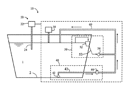
time, or for certain amount
of hours a day without taking into account the real time condition of the
water being treated and/or
1
CA 2930520 2017-08-30
CA 02930520 2016-05-12
WO 2015/087156
PCT/IB2014/002891
treated by the same centralized filtration system regardless of different
levels and types of
impurities. In addition, conventional centralized filtration systems operate
according to
certain defined periods of time, or for certain amount of hours a day without
taking into
account the real time condition of the water being treated and/or without
adjusting
operational parameters and filtration requirements to optimize efficiency of
the system in
view of the real time condition of the water being treated.
[0004] Conventional centralized pool filtration systems therefore have high
equipment costs and
consume large amounts of energy to complete such filtration requirements. The
Association
of Pool and Spa Professionals estimates that there are more than 5.5 million
swimming pools
in the United States equipped with conventional centralized filtration
systems. According to
the U.S. Department of Energy, conventional pool filtration systems are very
energy intensive,
using up to 3,000 kWh of electricity per year, the equivalent of about 30% of
an average
household's electricity consumption, as per the Energy Information
Administration. The
California Energy Commission estimates that a typical backyard swimming pool
in California
can use enough energy during the summer season as would be needed to power an
entire
home for three months. Reducing the amount of energy needed for filtration
would provide
savings in the cost of maintenance of the pools and also reduce CO2 emissions.
[0005] The cost and high energy demand of operating a pool with conventional
centralized filtration
systems has caused closures of some large public swimming pools around the
world. For
example, according to the Japan Times, the "Ocean Dome" indoor swimming pool
located in
Japan (which holds the Record Guinness as the largest indoor swimming pool in
the world,
with over 1 hectare of water surface) had to be closed in 2007 due to high
operational costs.
Another example is the "Fleishhacker Pool" located in California, with a
surface of 1.5
hectares, which had to be closed on 1971 due to water quality problems and
high costs.
[0006] With a trend toward more sustainable and ecological practices,
regulatory agencies
throughout the world are enacting regulations that aim to lower energy
consumption and
reduce CO2 emissions of swimming pool operations. Because of the need for
lower energy
consumption and more cost effective filtration systems, it is desirable to
have a method that is
capable of maintaining water quality at a lower capital and operating cost. A
trend toward
more sustainable operations is also driving the need for more energy efficient
systems and
methods for maintaining water quality in large water bodies, such as swimming
pools.
2
CA 02930520 2016-05-12
WO 2015/087156
PCT/IB2014/002891
Previous Art
[0007] Turbidity of water can be used as a measure of water quality. Turbidity
is caused by
microscopic suspended solid particles that result in "cloudiness" of the
water. The particles
may include many different types of impurities, such as inorganic and organic
particles,
microbes, and algal growth. Turbidity of water can be reduced, for example, by
filtration or by
causing the particles to agglomerate or react with chemicals, making them
heavy enough to
settle to the bottom. U.S. Patent No. 4,747,978 discloses a method of
disinfecting swimming
pool water by use of calcium hypochlorite compositions including an inorganic
flocculant (e.g.,
aluminum sulfate) that can provide improved clarity upon addition to a body of
water, e.g., a
swimming pool. The '978 patent discloses that water clarity can be improved by
the
simultaneous settling of organic materials and suspended solids due to the
addition of the
flocculant, but at the same time discourages the use of too much flocculant in
order to avoid
plugging the filtration system. Also, such method requires filtration of the
complete water
volume.
[0008] Chinese patent publication CN2292798 discloses a water circulation
treatment and
underwater dirt collecting device for a swimming pool including a treating and
circulating
water discharging impurities. The '798 publication discloses adding
flocculant, algaecide
sterilizing agent and pH regulating agent to the water, filtering the water
and returning the
water back to the swimming pool. The dirt is suctioned from the bottom of the
pool by a dirt
collecting disc which moves along the bottom, and the sediment accumulated at
the bottom
of the pool is discharged out of the pool. However, even in this treatment
system, the entire
body of water is filtered. The '798 publication does not address the issues
associated with high
filtration volumes and does not disclose controlling the operation of the
suctioning system or
the filtration system based on observed water quality parameters. The '798
publication also
fails to address the treatment of skimmed water that is typically sent through
the centralized
filtration system, thus adding to the total filtration volume.
Summary
[0009] The optimized system and method of the present invention replaces
conventional centralized
filtration systems from traditionally configured swimming pools with a
simplified economic
filtration system and degreasing system that consumes up to two orders of
magnitude less
energy, and requires much smaller filtration equipment than conventional
filtration systems.
The method replaces the three filtration requirements from conventional
centralized filtration
3
CA 02930520 2016-05-12
WO 2015/087156
PCT/1B2014/002891
systems used in swimming pools, which are: the filtration of the entire body
of water
contained in the swimming pool; the filtration of the water suctioned from the
bottom that
contains settled impurities; and the filtration of the surface water drawn by
a skimmer
system. In such a conventional system, the three water flows are sent to the
same centralized
filtration system in order to remove suspended solids, floating debris and
greases.
[0010] The disclosed system and method provide for a significantly lowered
need for filtration
capacity by suctioning a small water flow from the bottom of the large water
body (e.g., a
pool) that contains settled impurities, thus avoiding filtration of the entire
body of water and
the centralized filtration of skimmed water is replaced by screening of debris
and skimming of
oil and grease. The system and method of the invention allows activating the
operation of
specific systems based on the received information regarding different water
quality and
physicochemical parameters. These parameters often include turbidity, the
color of the
bottom of the water body, and amount of greases on the surface water layer of
the water
body, which can be directly or indirectly measured, empirically estimated,
determined
according to experience, based on sensorial methods, or calculated. The
chemical application
system, mobile suctioning device, and degreasing system are each operated only
when
needed based on the actual need for filtration or purification dictated by the
quality and
physicochemical parameters of the water in the water body, such as turbidity
of the water,
amount of settled impurities, and/or amount of greases or oils on the surface
water layer of
the water body, rather than a pre-set schedule or required filtration rates as
in conventional
centralized swimming pool filtration systems.
[0011] The method additionally provides for adding a chlorine-based additive
to the water to
maintain a minimum free residual chlorine level in the water body or in a
specific bathing
zone, where such minimum free residual chlorine concentration is considerably
lower than
conventional concentrations used in swimming pools as the large water bodies
from the
present invention have large water volumes that provide an additional dilution
effect. The
minimum free residual chlorine level from the present invention is based on
the WQI which
comprises a group of variables that are not usually applied in small water
volumes such as
swimming pools.
[0012] The method for treating a large water body generally includes applying
an effective amount of
a flocculant to water in the water body to maintain turbidity of the water
below 2 NTU,
wherein the flocculant flocculates impurities in the water into particles that
settle to the
bottom of the water body; operating a mobile suctioning device to maintain the
increase in
4
20 mg/L of floating greases, wherein greases from a surface water flow into
the degreasing system are
removed by a separation unit comprising a degreaser and the treated water is
returned to the water
body.
[0012a] According to an aspect, the present invention provides a method for
treating large water bodies
for recreational uses, comprising large artificial excavated or floating
structures with bottoms comprising
flexible membranes, wherein the method comprises: applying an effective amount
of a flocculant to
water in the water body to maintain turbidity of the water below 2 NTU,
wherein the flocculant
flocculates suspended solids in the water into particles that settle to the
bottom of the water body;
operating a mobile suctioning device to adjust a color of a bottom of the
water body within a set limit by
moving on the bottom of the water body and suctioning a portion of water from
the bottom of the water
body containing settled particles, the operation being performed to maintain
an increase in a black
component of the color of the bottom below 30% based on a CMYK scale, wherein
the mobile suctioning
device moves and suctions at a rate of 10,000 m2 per 24 hours, and wherein
operating the mobile
suctioning device does not re-suspend more than 30% of the settled particles
in an area on the bottom
of the water body cleaned by the mobile suctioning device; filtering the water
suctioned by the mobile
suction device to produce a filtered water, and returning the filtered water
to the water body, wherein
the water suctioned by the mobile suction device does not exceed 10% of the
total water volume of the
water body in a 24 hour interval; and operating a degreasing system to
maintain a surface water layer
having less than 20 mg/L of floating greases within a top-most 1 cm of the
surface water layer, wherein
greases from the surface water layer flow into the degreasing system, wherein
the degreasing system
comprises a skimmer system and a separation unit comprising one or more
screens for retaining large
debris and an overflow apparatus for separating water from oils and greases
through overflow, wherein
the skimmer system provides a surface water flow from the water body to the
separation unit, and
wherein the water that has passed through the degreasing system is returned to
the water body; and
wherein a control system activates the application of flocculants, the
filtration of the water suctioned by
the mobile suctioning device, and the operation of the degreasing system.
[0012b] According to another aspect, the present invention provides a system
for maintaining water
quality in a large water body for recreational uses, comprising: a chemical
application system configured
for dosing a flocculant into the water, wherein the chemical application
system applies a flocculant to
the water in the water body to maintain turbidity of the water below 2 NTU; a
mobile suctioning device
configured for moving along the bottom of the water body and suctioning a
portion of water from the
bottom
CA 2930520 2019-02-08
containing settled solids, wherein the mobile suctioning device is activated
before the increase in the
bottom's color black component exceeds 30% on a CMYK scale and wherein
operating the mobile
suctioning device does not re-suspend more than 30% of the settled particles
in the area on the bottom
of the water body cleaned by the mobile suction device; a filtration unit in
fluid communication with the
mobile suctioning unit, wherein the filtration unit is configured for
receiving the portion of water
suctioned by the mobile suction unit; and a degreasing system comprising a
skimmer system and a
separation unit comprising one or more screens for retaining large debris and
an overflow apparatus for
separating water from oils and greases through overflow, wherein the skimmer
system provides a
surface water flow from the water body to the separation unit, wherein the
degreasing system is
activated to maintain a surface water layer having less than 20 mg/L greases
within a top-most 1 cm of
the surface water layer; and one or more return lines for returning filtered
water from the filtration unit
and the degreasing system to the water body; and a control system configured
for activating the
application of flocculants, the filtration of the water suctioned by the
mobile suctioning device, and the
operation of the degreasing system.
[0012] In an embodiment, the system includes a control system that can
activate the operation of the chemical
application system, mobile suctioning device, and/or degreasing system based
on received water quality
and physicochemical parameters including turbidity, the color of the bottom of
the water body, and
amount of greases on the surface water layer of the water body, to adjust the
water quality and
physicochemical parameters within predetermined limits.
[0013] The system for maintaining water quality in a large water body
generally includes a chemical application
system for dosing a flocculant into the water, wherein the chemical
application system is activated to
apply flocculants to the water in the water body to maintain turbidity of the
water below 2 NTU, and
for optionally applying a chlorine based additive to maintain a minimum free
residual chlorine level in
the water; a mobile suctioning device capable of moving along the bottom of
the water body and
suctioning a portion of water from the bottom containing settled solids, where
the mobile suctioning
5a
CA 2930520 2018-06-14
,
device is activated when the bottom's color black component increases more
than 30% on a CMYK
scale; a filtration unit in fluid communication with the mobile suctioning
unit, wherein the filtration
unit receives the portion of water suctioned by the mobile suction unit; a
degreasing system for
providing a surface water flow from the water body to the separation unit,
wherein the degreasing
system is activated to maintain a surface water layer having less than about
20 mg/L of floating
greases; and one or more return lines for returning filtered water from the
filtration unit and the
degreasing system to the water body.
Brief Description of Figures
FIG. 1 shows an example of a conventional centralized filtration system.
FIG. 2 shows an embodiment of a system for maintaining water quality in a
pool.
FIG. 3 shows an embodiment of the system of Figure 2.
FIG. 4 shows an embodiment of the system of Figure 2.
5b
CA 2930520 2018-06-14
CA 02930520 2016-05-12
WO 2015/087156
PCT/1B2014/002891
FIG. 3 shows an embodiment of the system of Figure 2.
FIG. 4 shows an embodiment of the system of Figure 2.
Detailed Description
[0015] The following detailed description refers to the accompanying drawings.
While embodiments
of the invention may be described, modifications, adaptations, and other
implementations are
possible. For example, substitutions, additions, or modifications may be made
to the
elements illustrated in the drawings, and the methods described herein may be
modified by
substituting, reordering, or adding stages to the disclosed methods.
Accordingly, the
following detailed description does not limit the scope of the invention.
While systems and
methods are described in terms of "comprising" various apparatus or steps, the
systems and
methods can also "consist essentially of" or "consist of' the various
apparatus or steps, unless
stated otherwise. Additionally, the terms "a," "an," and "the" are intended to
include plural
alternatives, e.g., at least one, unless stated otherwise. For instance, the
disclosure of "a
disinfectant agent," "an inlet line," "a mobile suction device," etc., is
meant to encompass
one, or more than one, disinfectant agent, inlet line, mobile suction device,
etc., unless
otherwise specified.
[0016] Conventional centralized filtration systems in swimming pools typically
require filtration of the
entire body of water about 1 to 6 times per day. In such filtration systems,
water from
different sources, such as intake pipes, suctioning devices, drains, skimmers,
and overflow is
collected and sent to a centralized filter.
[0017] The present invention is directed to a method and system for treating
large water bodies,
where the large water bodies can be artificially constructed on land such as
excavated
structures, or floating structures installed within natural or artificial
lakes, ponds, basins,
rivers, the sea, or others. The term "water body" as used herein refers to any
body of water,
either artificially constructed on land or a floating structure, generally
capable of being used
for recreational use or for sports, includinipools, lagoons, tanks, lakes,
water features,
artificial ponds, artificial lakes, floating lagoons, and the like. The large
water bodies of the
present invention generally have a water surface area of at least about 7,000
m2. In some
embodiments the large water body may have a surface area of 20,000 m2, 40,000
rn2, 100,000
m2, or more.
6
CA 02930520 2016-05-12
WO 2015/087156
PCT/1B2014/002891
[0018] The water body can be constructed with characteristics that are
suitable for performing the
method of the present invention, where the bottom comprises a non-porous
flexible material
such as a flexible membrane. Such non-porous flexible material is not used
generally for
conventional concrete swimming pools, but it is used for large water bodies
such as retention
and irrigation ponds, and for example small kids above ground pools, and other
large water
bodies due to its flexibility that allows for easier installation and provides
structural
advantages compared with non-flexible materials such as concrete used in
conventional
swimming pools, also having lower costs.
[0019] The non-porous flexible material preferably comprises a liner, such as
a membrane or plastic
liner, and may have a thickness in the range of about 0.1 mm to about 5 mm.
Examples of
suitable materials include, but are not limited to, rubbers, plastics, Teflon,
low density
polyethylene, high density polyethylene, polypropylene, nylon, polystyrene,
polycarbonate,
polyethylene terephthalate, polyamides, PVC, acrylics, and combinations
thereof. In other
embodiments, the liner can be constructed of composite materials. According to
embodiments, the liner allows avoiding adherence of settled impurities
produced by the
method's processes or natural falling debris, dust, pollen, or other suspended
solids that fall
into the bottom of the water body.
[0020] In an embodiment, the method and system from the present invention is
used on artificially
constructed inland water bodies. In order to build such water bodies,
earthworks may be
required to excavate a hole in the ground to generate a desired depth for the
water body. The
non-porous flexible material (e.g., a membrane or plastic liner) may be
installed on the
bottom of the excavated water body. The non-porous material can be thermo
fused, or an
extruded HDPE concrete embedment strip can be used for liner attachment to
provide an
even layer in the bottom and provide the non-permeable properties to the
bottom of the
water body.
[0021] Earthworks and soil compaction may be used to provide slopes within the
water body (e.g., a
sloping bottom). According to an embodiment, the slope of the bottom is
preferably no
greater than 20% in order to allow a mobile suctioning device to move along
the bottom of
the water body.
[0022] The walls of the water body may be sloped or vertical. In an
embodiment, the slope of the
walls is no less than about 45% in order to avoid attachment of settling
solids, debris, or other
impurities on the walls. Preferably, the slope of the walls of the water body
are greater than
7
CA 02930520 2016-05-12
WO 2015/087156
PCT/1B2014/002891
about 60% in order to avoid any accumulation of settled solids, debris, and
the like on the
walls. In an embodiment, the slope of the walls is greater than about 80%. In
another
embodiment, the slope of the walls is greater than about 90%.
[0023] The soil conditions in the location where the water body is constructed
preferably allow for
generating a compacted soil with low permeability. During construction of the
water body, the
soil may be compacted more or less depending on the particle size of the soil.
Soil compaction
can be measured as a percentage of the relative density (RD) of the soil or as
a percentage of
the soil's most dense state, the maximum dry density (MDD). Relative density
of the soil and
methods used to calculate relative density are defined in ASTM D4254-00
(2006). The
maximum dry density (MDD) of the soil can be determined according to a
modified proctor
compaction test according to ASTM D1557-12. The compacted soil should attain a
degree of
compaction based on a mesh test of N 200 with an opening of 0.075 mm.
[0024] According to an embodiment, if the amount of soil passing through the N
200 mesh (the
"passage rate") is less than 12%, the soil should be compacted to at least
about 80% of its
relative density (RD). If the amount of soil passing through the N 200 mesh is
12% or higher,
the soil should be compacted to at least about 85% of its maximum dry density
(MDD).
[0025] The natural terrain may also be leveled to accommodate the water body
and related
equipment and facilities. The top layer of the natural terrain may contain
organic matter and
may be removed to avoid using such soil for compaction and structuring the
slopes.
Preferably, the removed layer of soil is at least 5 cm, more preferably at
least 10 cm, and most
preferably at least 25 cm. The walls of the excavated water bodies can be
built out of soil and
can be reinforced with concrete or other materials, or can be built out of
structural materials
such as concrete or others, which may provide structural stability to the
water body. In an
embodiment, the walls of the water body may also comprise non-porous flexible
membranes.
[0026] Figure 1 shows a typical example of a conventional centralized
filtration system for a water
body. In the conventional centralized filtration system, water is drawn from
three separate
sources: a main body of water 170; water from the bottom of the water body 142
containing
settled impurities; and surface water from skimmers 152. The water drawn from
all three
sources is sent through a centralized filter 180 and after filtration sent
back into the pool 100
through a return line 160. Because of the high volume of filtration required,
the cost of
operating such filtration systems is high. Filtration of the water in a
conventional filtration
system is not based on observed requirements but is usually operated
continuously at a set
8
CA 02930520 2016-05-12
WO 2015/087156
PCT/1B2014/002891
rate or for set periods of time throughout the day without regard to actual
water quality.
Surface water drawn by skimmers is filtered in the centralized filtration
system regardless of
the fact that oil, grease and floating debris may be removed by more efficient
means and
without filtration.
[0027] In some existing systems the skimmers perform a double function, where
the water drawn
from both the surface water and the main body of water 170 are drawn through
the skimmer
system 152 to be sent into the centralized filter 180. In this case, the
surface water and main
body of water are drawn through the skimmer system, and the result of the two
water flows is
sent into the centralized filter 180. Therefore, the skimmers cover a double
function of
renovating the water by filtering the total water volume from 1 to 6 times per
day and also
removing floating surface impurities. However, while the two water flows
(surface water and
main water body) are drawn through the skimmers, the total water flow and
filtered water
volume remains unchanged as the filtration requirements for the centralized
filter still include
the filtration of the total water body from 1 to 6 times per day, and
therefore the centralized
filter would still be required to have a very large capacity, and hence a very
large energy
consumption. Also, the filtration requirements of the surface water are
usually completely
different than the filtration requirements for the main water body. If for
example, just the
surface water was filtered, the amount of energy consumption for filtration
would be reduced
by 2 orders of magnitude compared to filtering the surface water together with
the main
water body from 1 to 6 times per day.
[0028] The present invention includes a method and system for maintaining
water quality that
provides for elimination of the large centralized filtration system in water
bodies. The system
of the invention includes a chemical application system, mobile suctioning
device, filtration
system, and/or degreasing system that are activated based on the information
received
regarding specific water quality and physicochemical parameters such as
turbidity, the color
of the bottom of the water body, and amount of greases on the surface water
layer.
[0029] According to a method of the present invention, a chemical agent, such
as a flocculant, can be
added to prevent the turbidity of the water from exceeding a predetermined
Nephelometric
Turbidity Unit (NTU) value. The term "flocculant" as used herein refers to a
chemical agent or
composition that promotes or induces agglomeration, coagulation, or
flocculation of
impurities, such as suspended solids, organic matter, inorganic matter,
bacteria, algae, and
the like, in the water body into particles or "floccules" which then settle to
the bottom of the
water body. As used herein, the term "settled impurities" refers to the
particles, floccules, or
9
CA 02930520 2016-05-12
WO 2015/087156
PCT/1B2014/002891
other debris such as dust, pollen, and the like, that have settled to the
bottom of the water
body. A mobile suctioning device capable of moving along of the bottom of the
water body,
can be activated to remove settled particles from the bottom of the water
body. The mobile
suctioning device can be used in the bottom of the water bodies, where such
bottoms
comprise a non-porous flexible liner, such as a membrane or plastic liner as
described herein.
[0030] The water bodies may be artificially constructed inland as excavated
structures or floating
structures installed within large lakes, basins, ponds, rivers, the sea, or
others. In an
embodiment, the mobile suctioning device is supported over brushes to avoid
damaging the
bottom of the land-based artificially constructed excavated structures or of
the floating
structure. In an embodiment, the suctioning device is a self-propelled device.
In another
embodiment, the suctioning device allows concentration of suctioning power at
suction points
distributed along the bottom of the device, which allows avoiding re-
suspension of the settled
solids and debris found on the bottom of the water bodies, and therefore
providing higher
suctioning efficiency. In an embodiment, the suctioning device is capable of
cleaning at a
surface cleaning rate of 10,000 m2 per 24 hours.
[0031] The mobile suctioning device suctions a portion of the water from the
bottom of the water
body containing the settled particles. A filtration unit in fluid
communication with the mobile
suction device can receive the suctioned water flow from the mobile suctioning
device and
filter the water, which is then returned to the water body. The timing of the
suctioning and
filtration of water containing settled particles from the bottom of the water
body can be
based on actual need and not according to certain defined periods of time or
certain amount
of hours per day as in a conventional centralized filtration system.
[0032] Also, it must be noted that conventional swimming pools require
maintaining high and
permanent residual chlorine levels to allow proper disinfection in case
contamination enters
the swimming pools, as swimming pools have small water volumes. On the other
hand, the
present invention provides an innovative method where the minimum residual
chlorine level
is based on the Water Quality Index, which allows incorporating different
variables that are
applicable to large water bodies to determine its water quality and therefore
estimate the
minimum free chlorine level. This allows providing a minimum residual chlorine
level that is
considerably lower than for conventional swimming pools, as the quality of
large water bodies
can be assessed through different parameters not usually applied for
conventional swimming
pools, and also since large water bodies provide an additional dilution effect
which allows
maintaining lower chlorine concentrations than for conventional small sized
swimming pools.
CA 02930520 2016-05-12
WO 2015/087156
PCT/1B2014/002891
[0033] The Water quality index (WQI) is a dimensionless number that allows
combining different
water quality parameters into a single index by normalizing values to
subjective rating curves.
The WQI has been used for evaluating the quality of water of large water
bodies such as lakes,
lagoons, rivers and others, and factors included in the WQI can be modified
depending on the
designated water use of the water body or specific preferences. The NSF
(National Sanitation
Foundation) Water Quality Index can be determined by using eight common water
quality
parameters including dissolved oxygen, fecal coliform bacteria, pH, 5-day BOO
(biochemical
oxygen demand), total phosphorus, nitrate-nitrogen, turbidity, and total
dissolved solids or
,may be determined through empirical methods, algorithms based on experience,
and
analytical methods. The WQI takes the complex scientific information of these
variables and
synthesizes into a single number.
[0034] The water quality of the assessed water body as determined by WQI can
range from good,
fair, to poor water quality. In an embodiment, the Water Quality Index can be
determined by
weighting the parameters to allow proper influence in the index:
Table 1: Weights applied to WQI Parameters
Parameter WQI Weight
Dissolved Oxygen 0.17
Fecal Coliform Density 0.16
pH 0.11
BOD5 0.11
Nitrates 0.10
Total Phosphates 0.10
Turbidity 0.08
Total Dissolved Solids 0.07
Temperature Change 0.10
[0035] The weights can be adjusted so that they add up to 1 in case the number
of factors is not 9.
Generally, the ranges for evaluating the WQI are as follows:
Table 2: WQI Ranges
WQI Rating
90-100 Excellent Water Quality
70-90 Good Water Quality
50-70 Poor Water Quality
11
CA 02930520 2016-05-12
WO 2015/087156 PCT/1B2014/002891
25-50 Very Poor Water Quality
0-25 Very bad water quality
[0036] Turbidity, oxygen demand, nutrients, and bacterial counts allow for
assessing the water
quality of the specific water body that is being analyzed in order to provide
proper treatment.
[0037] Application of a chlorine-based additive is activated in order to
maintain at least a minimum
free residual chlorine level. In an embodiment of the invention, the
activation of the
application of a chlorine-based additive is done through a control system. In
an embodiment,
application of a chlorine based additive is activated to maintain a minimum
free residual
chlorine level, where the minimum free residual chlorine level cannot be lower
than the value
resulting from the following equation:
Minimum Free Residual Chlorine Level = (0.3 ¨ 0.002 (WQI ¨ 100)) ppm
[0038] An exemplary water quality analysis is presented in Table 3 below:
Table 3: Example
Measured Value Normalized Q Value
Parameter
(From WQI Definition)
Dissolved Oxygen 40 % Saturation 30
Fecal Coliform Density 2 NMP/100 ml 91
pH 8 84
BOD5 5 mg/L 56
Nitrates 10 mg/L 51
Total Phosphates 1,1 mg/L 40
Turbidity 0,3 NTU 98
WQI 63 Based on 7 factors
[0039] The weights are adjusted for 7 factors. The calculated WQI index is 63,
and the minimum free
chlorine level in the water may be calculated as follows:
Minimum Free Residual Chlorine Level = (0.3 ¨ 0.002(63 ¨ 100))ppm
Minimum Free Residual Chlorine Level = 0.374 ppm
[0040] According to an embodiment, the minimum amount of chlorine in the water
is maintained at
or above the level determined by the above calculation.
12
CA 02930520 2016-05-12
WO 2015/087156
PCT/1B2014/002891
[0041] If required, the level of free residual chlorine may be determined
through many different
methods, including empirical methods, analytical methods, algorithms based on
experience,
sensorial methods, and regulatory requirements. In one embodiment, the free
residual
chlorine level is not lower than the value resulting from the equation for
determining
minimum free residual chlorine level as disclosed above. In an embodiment, the
minimum
residual chlorine level is maintained continuously in the water. For example,
the minimum
residual chlorine level is maintained continuously in the water for a period
to time, such as for
a week or months at a time, for operation during daylight, or for the duration
of a swimming
season. In another embodiment, the minimum residual chlorine level is
maintained while the
water body is in use.
[0042] The method of the invention further provides a degreasing system that
replaces the
centralized filtration of skimmed water in a conventional centralized
filtration system.
Operation of the degreasing system of the method of the invention is typically
based on the
amount of greases found on the surface water layer, which in combination with
application of
the chemical agent to regulate turbidity of the water body, and the timing of
the suctioning
and filtration of the portion of water containing settled particles from the
bottom of the water
body based on actual need, provides a method capable of maintaining water
quality without
complete filtration of the water body.
[0043] Figures 2-4 show embodiments of a system 10 and method according to the
invention for
maintaining water quality in a water body.
[0044] In an embodiment, the system 10 includes a control system for
maintaining the quality of the
water in the water body 1 within predetermined water quality and
physicochemical
parameters. The control system activates the addition of chemical agents, the
removal of
impurities from the water, and the removal of greases from the surface water
layer based on
water quality and physicochemical parameters. The control system is configured
to receive
information about certain water quality and/or physicochemical parameters,
process the
information, and initiate processes (e.g., chemical application, suctioning,
filtration, and
degreasing).
[0045] According to an exemplary embodiment shown in Figure 2, the control
system comprises a
coordinating assembly 20 that may include a control unit 22, such as a
computer, and at least
one monitoring device 24, such as a sensor. The sensor may be a turbidity
meter or other
means for determining turbidity of the water. According to other embodiments,
the
13
CA 02930520 2016-05-12
WO 2015/087156
PCT/1B2014/002891
coordinating assembly 20 may include two or more monitoring devices 24. For
example, the
coordinating assembly 20 may include a monitoring device for monitoring color,
e.g., a
colorimeter, used for determining the color of the bottom 2 of the water body
1. The
coordinating assembly 20 may also comprise additional monitoring devices 24
for other water
quality parameters, such as pH, alkalinity, hardness (calcium), chlorine, and
microbial growth.
[0046] According to an embodiment, the control system for coordinating the
addition of chemical
agents and filtration comprises an automated system. The automated system may
be
programmed to monitor water quality parameters continuously or at pre-set time
intervals,
and to compare the results to a predetermined value. For example, the
automated system
may initiate addition of chemical agents for removing impurities from the
water, operation of
the mobile suction device, and/ or operation of the degreasing system upon
detecting a
crossing of a value. According to an alternative embodiment, the control
system comprises
manually activating the addition of chemical agents, operation of the mobile
suction device,
and/ or operation of the degreasing system based on a determination of water
quality and
physicochemical parameters.
[0047] The control system may comprise an automated system that can be
operated on site or
remotely through the internet or other similar information-exchange systems.
Such control
system allows automatically and operating the processes and activating
different systems
within different periods of time. According to alternative embodiments, the
activation of the
processes may be completed by one or more people that manually obtain and/or
enter
and/or process information, or initiate and/or perform processes for
maintaining water
quality parameters.
[0048] Figure 3 shows an embodiment of the system where the control system
comprises visual or
optical inspection of water quality parameters. In the embodiment, water
quality and
physicochemical parameters can be obtained manually, for example by visual
inspection,
sensorial methods, algorithms based on experience, or by obtaining a sample
and measuring
water quality using analytical or empirical methods. For example, the color of
the bottom 2 of
the water body 1 can be determined by visual inspection by comparing the color
of the
bottom 2 of the water body 1 to a color palette. The color of the bottom 2 of
the water body
1 can be visualized from the surface of the water, or, in particular when
turbidity is high (e.g.,
more than about 7 NTU), by using a transparent peephole attached to a tube
that allows
visualization of the bottom 2 of the water body 1.
14
CA 02930520 2016-05-12
WO 2015/087156
PCT/1B2014/002891
[0049] In an embodiment, the system 10 provides for adding chemical agents to
the water.
According to an embodiment shown in Figure 2, the system comprises a chemical
application
system 30. The chemical application system 30 may be automated and may be
controlled by
the control unit 22 of the coordinating assembly 20. The chemical application
system 30 may
comprise at least one chemical reservoir, a pump for dosing chemicals, and a
dispensing
apparatus. The pump may be actuated by a signal from the control unit 22. The
dispensing
apparatus may comprise any suitable dispensing mechanism, such as an injector,
a sprinkler, a
dispenser, piping, or combinations thereof.
[0050] According to an alternative embodiment, as shown in Figure 3, the
chemical application
system 30 may be operated manually based on monitoring of water quality
parameters. For
example, the water quality parameters can be obtained manually, by empirical
or analytical
methods, algorithms based on experience, visual inspection, sensorial methods,
or by using a
sensor, and the information about the water quality parameters can be
processed manually or
by entering into a processing device (e.g., a computer). Based on the
information about the
water quality parameters, operation of the chemical application system 30 may
be activated
manually, e.g., by activating a switch.
[0051] In yet another embodiment shown in Figure 4, chemicals may be dosed
manually into the
water or by using a separate chemical application mechanism. For example,
water quality
parameters can be obtained manually, visually, by sensorial methods,
algorithms based on
experience, or by using a sensor, and the information about the water quality
parameters can
be processed manually or by entering into a processing device (e.g., a
computer). Based on
the information about the water quality parameters, chemicals can be manually
added into
the water.
[0052] The system 10 typically comprises a filtration system 40. As seen in
the embodiments of
Figures 2-4, the filtration system 40 includes at least one mobile suctioning
device 42 and a
filtration unit 44. The mobile suctioning device 42 is configured to suction a
portion of water
from the bottom 2 of the water body 1 that contains debris, particulates,
solids, flocs, and/or
other impurities that have settled on the bottom 2. Suctioning and filtering
this portion of the
water volume in the water body provides the desired water quality without a
filtration system
that filters the entire water volume of the water body, which is in contrast
to conventional
swimming pool filtration technologies that require filtering the entire water
volume 1 to 6
times per day, have large capital costs, and consume large amounts of energy
to complete
such filtration requirements.
CA 02930520 2016-05-12
WO 2015/087156
PCT/1B2014/002891
[0053] According to an embodiment, the mobile suctioning device 42 is capable
of moving along the
bottom 2 of the water body 1. However, to maximize the efficiency of removal
of debris,
particulates, solids, flocs, and/or other impurities that have settled on the
bottom 2, the
mobile suctioning device 42 can be configured such that its movement creates
minimal
dispersion of the settled materials. In an embodiment, the mobile suctioning
device 42 is
configured and operated to avoid the re-suspension of less than 30% of the
settled materials
that are found on the bottom. In an embodiment, the mobile suctioning device
42 is
configured to not include parts, such as rotating brushes that could function
to re-disperse a
substantial portion of the settled materials from the bottom 2 of the water
body 1 during
operation of the suctioning device.
[0054] The operation of the mobile suctioning device 42 can be controlled by
the control unit 22 or
manually by an operator. According to an embodiment shown in Figure 2, the
operation of
the suctioning device 42 can be controlled by the control unit 22. In an
alternative
embodiment shown in Figure 3, the operation of the suctioning device 42 can be
controlled
manually by an operator.
[0055] The mobile suctioning device 42 may comprise a pump, or a separate pump
or pumping
station may be provided to suction the water and to pump the suctioned water
to the
filtration unit 44. The separate pump or pumping station may be located within
the large
water body 1, along the perimeter of the water body 1, or outside of the water
body 1.
[0056] It is also considered within the scope of the invention to incorporate
a filtration unit directly
into the mobile suctioning device 42 itself.
[0057] The mobile suctioning device 42 is typically in fluid communication
with the filtration unit 44.
The filtration unit 44 generally includes one or more filters, such as a
cartridge filter, sand
filter, micro-filter, ultra-filter, nano-filter, or a combination thereof. The
mobile suctioning
device 42 is typically connected to the filtration unit 44 by a collecting
line 43 comprising a
flexible hose, rigid hose, or a pipe, among others. The capacity of the
filtration unit 44 is
generally scaled to the capacity of the mobile suctioning device 42. The
filtration unit 44
filters the water flow from the mobile suctioning device 42, corresponding to
a small portion
of the volume of water in the water body 1. Filtered water from the filtration
unit 44 is
returned to the water body 1 by a return line 60 comprising a conduit, which
can be a flexible
hose, rigid hose, a pipe, an open channel, or a combination thereof. Compared
to a
conventional centralized filtration system with capacity to filter the entire
body of water in a
16
CA 02930520 2016-05-12
WO 2015/087156
PCT/1B2014/002891
water body 1 to 6 times per day, the filtration unit 44 is generally
configured to have a
filtration capacity that does not exceed 30% of the total water volume of the
water body 1 in a
24 hour interval. Typically, the filtration capacity does not exceed 20% of
the total water
volume of the water body 1 in a 24 hour interval, and in a preferred
embodiment it does not
exceed 10% of the total water volume. The energy consumption of the filtration
system is
roughly proportional to size and, thus, significant costs savings can be
expected with lower
energy consumption, and requiring smaller equipment for the filtration
process.
[0058] The system 10 further comprises a degreasing system 50. The degreasing
system SO can be
used to separate floating debris and oils and greases from the water. The
system 10 can
further include a skimmer system hydraulically connected to the degreasing
system 50, in
order to efficiently purify skimmed water. As shown in Figures 2-4, the
degreasing system 50
can include a skimmer system 52 that skims the surface water of the water body
1, in fluid
connection by a connecting line 53 with a separation unit 54. Because of the
different nature
and quality of impurities (e.g., oils, greases, and floating debris) in
skimmed water as
compared to impurities in the bottom 2 of the water body 1, the skimmed water
usually does
not need to be filtered; however it is considered within the scope of the
invention to include a
filter in the degreasing system 50. Therefore, according to an embodiment, the
separation
unit 54 comprises a degreaser (e.g., an over flow apparatus) for separating
oils and greases
from the water and a screen or coarse filter for separating debris or a
conventional filter.
Water from the separation unit 54 can be returned to the water body 1 through
a return line
60 comprising a flexible hose, rigid hose, a pipe, an open channel, or a
combination thereof.
The return line 60 may be the same, or may be separate from the return line
from the
filtration system 40. According to a preferred embodiment, the degreasing
system 50
includes multiple skimmers 52 that may be spread out along the perimeter of
the water body
1. The skimmers 52 can be evenly spaced along the perimeter such that each
skimmer 52 is
equidistant from an adjacent skimmer 52, or placed in an uneven pattern, e.g.,
concentrated
in an area of the water body 1 expect to have higher impurities to be skimmed.
The skimmers
can be placed within the water body, and comprise fixed skimmers, floating
skimmers, and
self-filtering skimmers.
[0059] The skimmers provide a surface water flow to the separation unit. The
operation of the
degreasing system 50 may be continuous or intermittent depending on the actual
needs of
the water. For example, operation of the degreasing system 50 can be based on
the amount
of greases on the surface water layer. In an embodiment, the skimmer system is
used to
17
CA 02930520 2016-05-12
WO 2015/087156
PCT/1B2014/002891
maintain a surface layer of water with less than about 40 mg/L of greases,
typically less than
about 30 mg/L and preferably less than about 20 mg/L. In an embodiment, the
degreasing
system 50 is activated before the top-most 1 cm of said surface water layer
contains more
than about 20 mg/L of floating greases. The operation of the skimming system
50 may be
controlled by the control unit 22 (Figure 2).
[0060] Water quality in the water body 1 is typically maintained by adding
chemical agents for
removing impurities from the water, activating the mobile suctioning device 42
to remove
settled impurities from the bottom 2 of the water body, and/or activating the
degreasing
system 50 to remove oils and greases from the surface water layer according to
monitored or
observed water quality parameters. Water quality in the water body 1 may be
obtained, for
example, for specific parameters such as turbidity, color, pH, alkalinity,
hardness (Calcium),
chlorine, microbial growth, among others. The chemical application system,
filtration system,
and/or degreasing system can be timely activated by the control system to
maintain the water
quality parameters within set limits. The systems can be activated based on an
actual need
(e.g., exceeding a water quality parameter), resulting in the application of
smaller amounts of
chemicals and using less energy than in conventional swimming pool water
treatment
methods.
[0061] In some embodiments, water bodies of the present invention are
considerably larger than
conventional swimming pools, and therefore homogeneity may not be achieved
throughout
the complete water body by using conventional chemical application systems.
Large water
bodies tend to generate "dead zones" or "stagnant zones" which are not
affected by the
chemicals due to currents, mixing, winds, or other effects, and which may not
present the
same conditions as the rest of the water body. The application of additives in
the present
invention is done such that the water body does not have considerable water
quality
differences. According to an embodiment, the differences in water quality
between two
different locations is not higher than 20 %, for periods of time longer than 4
hours. The
chemical application systems from the present invention comprise injectors,
sprinklers,
dispensers, manual application, and piping.
[0062] In embodiments, water quality parameters can be obtained manually, for
example by visual
inspection based on experience, by sensorial methods, by using a water quality
meter (e.g., a
probe such as a pH probe, a turbidity meter, or a colorimeter), or by
obtaining a sample and
measuring water quality using an analytical method. Information about the
water quality
parameters can be obtained by or entered into the control system. In an
embodiment, an
18
CA 02930520 2016-05-12
WO 2015/087156
PCT/1B2014/002891
automated control system may be programmed to monitor water quality parameters
continuously or at pre-set time intervals, to compare the results to a
predetermined
parameter and to activate one or more systems when the parameter has been
crossed. For
example, the automated system may initiate addition of chemical agents,
operation of the
suctioning device, or operation of the degreasing system upon detecting a
crossing of a
predetermined parameter. In an alternative embodiment, water quality
parameters may be
obtained manually or visually through sensorial methods and the information
entered into the
control system, or the results may be compared to a predetermined value and
addition of
chemical agents, operation of the suctioning device, and/or operation of the
degreasing
system may be initiated manually. Chemical agents used to maintain water
quality in the
water body may comprise any suitable water quality treatment chemicals. For
example, the
chemical agents may comprise oxidants, flocculants, coagulants, algaecides,
sterilizing agents,
or pH regulating agents.
[0063] The turbidity of the water can be determined by a monitoring device 24
(system of Figure 2),
such as a sensor, by visual inspection, algorithms based on experience, and/or
empirical
methods (systems of Figures 3 and 4). Before the turbidity exceeds a
predetermined value, a
chemical agent, such as a flocculant, may be added to the water in the water
body to promote
or induce agglomeration, coagulation, or flocculation of impurities that cause
turbidity, such
as suspended solids, organic matter, inorganic matter, bacteria, algae, and
the like, into
particles, or "floccules", which then settle to the bottom of the water body
where they can be
removed by the mobile suctioning device. In an embodiment, the amount of
impurities that
have settled onto the bottom of the water body corresponds to an amount of
turbidity
removed from the water by the flocculant. Some settlement of impurities may
also happen
naturally without the addition of chemicals.
[0064] Generally, the flocculant is applied or dispersed into the water by the
chemical application
system. The flocculant may comprise a composition with synthetic polymers such
as
quaternary ammonium-containing polymers and polycationic polymers (e.g.,
polyquaternium), or other components with flocculant or coagulant properties.
Suitable
flocculants include but are not limited to multivalent cations (e.g., quats
and polyquats);
synthetic polymers (e.g., cationic polymers and anionic polymers); aluminum
salts, such as
aluminum chlorhydrate, alum, and aluminum sulfate; calcium oxide; calcium
hydroxide;
ferrous sulphate; ferric chloride; polyacrylamide; sodium aluminate; sodium
silicate; and some
natural agents such as chitosan, gelatin, guar gum, alginates, moringa seeds;
starch
19
CA 02930520 2016-05-12
WO 2015/087156
PCT/1B2014/002891
derivatives; and combinations thereof. In embodiments, the flocculant has
algaecide
properties which kills and/or prevents the growth of algae in the water body.
The use of
flocculants having algaecide properties can reduce the amount of chlorine or
other
disinfectants in the water body, thus reducing chemical consumption and
providing a
sustainable operation.
[00651 In an embodiment, addition of flocculants is initiated before turbidity
is equal to or exceeds a
predetermined value, such as 2 NTU, 3 NTU, 4 NTU, or 5 NTU. The control system
may be
used to initiate the addition of flocculants before turbidity of the water
exceeds a
predetermined value in order to cause the flocculation and settling of organic
and inorganic
matter. Typically an effective amount of flocculant is added to the water to
prevent the
turbidity from exceeding the 2 NTU. The fraction of water in which the
floccules collect or
settle is generally the layer of water along the bottom of the water body. The
floccules settle
at the bottom 2 of the water body 1 and can then be removed by the mobile
suctioning device
42 without requiring that all of the water in the water body 1 be filtered,
e.g., only a small
- fraction is filtered. The "small fraction" of water being filtered is
preferably less than about
10% of the total water volume of the water body in a 24 hour interval. In an
embodiment, the
small fraction of water being filtered is less than about 20% of the total
water volume of the
water body in a 24 hour interval. In another embodiment, the small fraction of
water being
filtered is preferably less than about 30% of the total water volume of the
water body in a 24
hour interval. The amount of flocculant added to the water can be
predetermined or can be
calculated (e.g., by the control device 22 in Figure 2 or manually as shown in
Figures 3 and 4)
based on the turbidity and the desired reduction in turbidity of the water.
Because the volume
of the body of water is large, different operating conditions may be used for
the filtration
system. In an embodiment, the filtration system is operated at the same time
as the
suctioning device and filtered is returned water to the water body
continuously.
[0066] The color of the bottom of the water body can have a significant
influence on the coloration of
the water, providing an aesthetically appealing coloration to the water in the
water body. The
bottom of the water body typically has a color that lends an aesthetically
pleasing color and
appearance to the water in the water body. For example, the bottom 2 of the
water body 1
may have a colored material with a white, yellow or blue color, among other
colors. The
settling of particulates, solids, flocs, and/or other impurities to the bottom
of the water body
may cause a change in the appearance of color of the bottom of the water body.
For
example, the settled impurities can make the color of the bottom 2 of the
water body 1
CA 02930520 2016-05-12
WO 2015/087156
PCT/1B2014/002891
appear darker than the original color. As the settled impurities collect on
the bottom 2 of the
water body 1, the color of the bottom 2 will become darker and thus the
coloration of the
bottom 2 will not be visible.
[0067] According to one method of the present invention, the operation of the
suctioning device 42
is activated when the color of the bottom of the water body exceeds a
predetermined value.
In an exemplary embodiment shown in Figure 2, the color of the bottom 2 of the
water body 1
is measured by a monitoring device 24 (e.g., a colorimeter) of the
coordinating assembly 20. If
the measured or perceived color of the bottom 2 of the water body 1 exceeds a
predetermined value, the operation of the mobile suctioning device 42 is
initiated by the
control unit 22 of the coordinating assembly 20. For example, a pump of the
mobile
suctioning device 42 can be actuated by a signal from the control unit 22. In
this way, the
mobile suction device 42 is operated only when needed based on the actual need
for filtration
or purification dictated by the quality of the water (e.g., an amount of
settled impurities
causing the color measurement to exceed the predetermined value) rather than a
pre-set
schedule.
[0068] In an exemplary embodiment, the color of the bottom of the water body
can be monitored for
changes in the black component on a CMYK. The CMYK color scale uses four
colors expressed
in percentages: cyan, magenta, yellow and black. The K¨component of the CMYK
scale is the
black component of the color. For example, a color with CMYK 15%, 0%, 25%, and
36%
represents a color with 15% cyan, 0% magenta, 25% yellow, and 36% black
component. The
black component of the bottom of the water body can be assessed by visually
comparing the
bottom color of the water body with standard CMYK charts or color palettes, by
sensorial
methods, empirical methods or algorithms based on experience, and determining
the black
component according to the percentage found in the CMYK chart.
[0069] Alternative color scales, such as the L*a*b* (or "Lab") scale, can also
be used. In the L*a*b*
scale, color is measured on three axis, L, a, and b, where the L-axis measures
lightness. An L-
value of 100 indicates white and L=0 indicates black. Thus, if the actual or
original color of the
bottom of the water body has, for example, an 1-value 75, the second value can
be
experimentally set at some lower L-value, such as 1=50. For example, when
impurities settle
on the bottom 2 of the water body land before the perceived color of the
bottom 2 reaches
L=50, the operation of the suctioning device 42 can be initiated.
21
CA 02930520 2016-05-12
WO 2015/087156
PCT/1B2014/002891
[0070] According to an embodiment shown in Figure 2, the color of the bottom 2
of the water body 1
is monitored by using a monitoring device 24, such as a colorimeter. According
to an
alternative embodiment shown in Figures 3 and 4, the color of the bottom 2 of
the water body
1 is monitored by visual inspection and/or by comparing the color to a
comparison chart or
color palette. In yet another embodiment, the color of the bottom 2 of the
water body 1can
be visualized from the surface of the water, or, in particular when turbidity
is high (e.g., more
than about 7 NTU), by using a transparent peephole attached to a tube that
allows
visualization of the bottom 2 of the water body 1. A visual inspection can
also be conducted
through, e.g., a strategically placed camera allowing for remote analysis of
the bottom 2 of the
water body 1.
(0071) The bottom of the water body ordinarily has a color that lends a
pleasing color and
appearance to the water in the water body. For example, the bottom 2 of the
water body 1
comprises a non-porous flexible membrane that may have a colored material such
as white,
yellow or blue. In an exemplary embodiment, the color of the bottom 2 of the
water body 1 is
measured by a monitoring device 24 (e.g., a colorimeter) of the control
assembly 20. The
perceived color of the bottom 2 of the water body 1 can be compared to its
actual, original or
desired color by empirical or analytical methods, such as algorithms based on
experience,
visual inspection, sensorial methods, comparison with color guides,
colorimeters,
spectrophotometers, and others.
[0072] The operation of the mobile suctioning device 42 can be activated
through the control system.
In an embodiment shown in Figure 2, the operation of the mobile suctioning
device 42 can be
activated by the control unit 22. In other embodiments shown in Figures 3 and
4, the
operation of the mobile suctioning device 42 can be activated manually.
[00731 According to an embodiment, before an increase in the measured or
perceived color of the
bottom of the water body exceeds a predetermined value (such as black
component equals
about 30% on a CMYK scale (or other suitable color scale)), the operation of
the mobile
suctioning device 42 can be initiated by the control unit 22 of the
coordinating assembly 20.
The increase in the black color component can be compared to its actual,
original or desired
color. For example, a pump of the mobile suctioning device 42 can be actuated
by a signal
from the control unit 22. The color of the bottom of the water body can be
further monitored
and compared to another predetermined value to determine an end point of the
operation of
the suctioning device 42. For example, if the black component of the color of
the bottom 2 of
the water body 1 decreases below the predetermined value, the operation of the
suctioning
22
CA 02930520 2016-05-12
WO 2015/087156
PCT/1B2014/002891
device 42 is discontinued. The predetermined value may be, for example, where
the black
component is 10 %-units above value of the black component of the actual color
of the
bottom 2, or 5 units above, or 3 units above. For example, if the original
color of the bottom 2
on the CMYK scale is 15 %, 0 %, 25 %, 10 % (the black component being 10%),
the
predetermined value can be set at 20 % black, 15 % black, or 13 % black.
Alternatively, the
predetermined value may be predetermined based on the actual color of the
bottom 2 of the
water body 1 and the desired level of cleanliness of the water body 1.
[0074] In one embodiment, each parameter has predetermined values, and the
appropriate
corrective measure is taken (e.g., addition of additives or activation of the
suctioning device
42) to adjust the water quality and maintain such parameters within their
predetermined
ranges or values. The corrective measure can be activated for a predetermined
period of
time, or until the parameters are adjusted. For example, if the turbidity has
a predetermined
value of 2 NTU, flocculants and other additives can be added to the water and
the value re-
determined until the value reaches 2 NTU or lower.
[0075] In an embodiment, the method is applied to different zones within a
water body, such as
bathing zones. In this embodiment, different areas of the water body can have
different
predetermined values. For example, in one area, the turbidity is adjusted to
be less than 2
NTU, respectively, while a second area may have maximum value of 3 NTU. By
having
different maximum values for different areas, it is possible to maintain
higher water quality in
predetermined areas, for example, in areas designated for bathing, i.e.,
bathing zones, while
allowing for slightly lower water quality levels in other areas.
[0076] The development of different water quality zones can be accomplished by
determining the
water quality parameters in each zone, as described herein, and comparing the
determined
parameter in each zone to the maximum predetermined value of that zone and
applying the
appropriate activity (e.g., adding flocculant, starting one or more skimmers
and/or activating
the suctioning device 42) only in the zone requiring such activity.
[0077] The system 10 and method of the present application provide the
benefits of a smaller and
more cost-efficient filtration system as compared to a conventional
centralized filtration
system and cheaper, more energy efficient operation. By using the system 10
and method of
the present application, the scale and operation of the filtration system can
be determined by
actual water quality parameters and, therefore, by actual need for filtration
or purification as
described herein, rather than a pre-set schedule of 1 to 6 pool volumes per
day regardless of
23
CA 02930520 2016-05-12
WO 2015/087156
PCT/1B2014/002891
real need. According to exemplary embodiments, a filtration system with a
capacity up to 60
times smaller than conventional systems may be used. Compared to a
conventional filtration
system with capacity to filter the entire body of water in the pool 6 times
per day, the system
of the present application can be configured to have a filtration capacity
that is 1/60 of the
conventional system, or capacity to filter 1/10 (one tenth ¨ 10%) of the water
body's volume
per day. According to alternative embodiments, the system can be configured to
a filtration
capacity that is capable of filtering up to 1/5 (one fifth ¨ 20%) of the water
body's volume per
day or more. The energy consumption of the filtration system is roughly
proportional to size
and, thus, significant energy savings can be expected when the filtration
system is operated
according to the present method.
Examples
[0078] The following examples are illustrative, and other embodiments exist
and are within the scope
of the present invention.
Example 1
[0079] The filtration needs of a large water body with a surface area of 2.2
ha (approximately 5.5
acres) and water volume of approximately 55,000 m3 (approximately 1,950,000
cubic feet or
14.5 million gallons) was studied by comparing a theoretical conventional
filtration system
with the method according to the present application. In the conventional
filtration system,
water drawn from the main body of water, the bottom of the artificially built
water body, and
surface water drawn by a skimmer system are all sent through a centralized
filtration system
sized for filtering the complete water volume 4 times per day.
[0080] In the method according to the present application, the water quality
is maintained based on
the different water quality parameters, where the parameters are determined by
algorithms
or based on experience and operated to maintain such parameters within its
limits. Also, only
the water from the bottom of the water body is sent through a filtration
system. Surface
water drawn from the degreasing system is sent through a degreaser and screens
to eliminate
oil, grease and floating debris. Table 4 shows the calculated filtration
capacity, filter size and
energy consumption for each system.
24
CA 02930520 2016-05-12
WO 2015/087156 PCT/1B2014/002891
Table 4: Comparison of Filtration Systems
Conventional Swimming Pool Method of the
Present
Parameter
Filtration Equipment
Application
Water Surface Area (m2) 22,000.00
22,000.00
Total Water Volume (m3) 55,000.00
55,000.00
Requirement for filtration of Filtering complete water body 4
complete water body times per day
Filtration Water Flow (m3/h) 9,167 90.0
Required Filter Size (m2) 284.36 1.78
Monthly Electricity Consumption 18,067.38 177.39
(kWh)
[0081] According to this example, the area utilized by the conventional
centralized filtration system is
more than 150 times larger than the area required by the filtration system of
the present
method, and the monthly energy consumption is about 100 times greater. As
demonstrated
by this Example, the present method allow for the use of much smaller, cost
and energy
efficient filtration systems for maintenance of water quality in water bodies.
Example 2
[0082] The method of the present application was applied to a large
recreational lagoon with a
surface area of about 9,000 m2 and a volume of about 22,500 m3. The lagoon was
equipped
with a suctioning device capable of suctioning water and settled impurities
from the bottom
of the lagoon having a flow rate of about 25 L/s, and 22 skimmers around the
perimeter of the
lagoon each having a flow rate of about 2.2 L/s. Water from the suctioning
device was sent to
a filtration system to remove impurities, and filtered water was returned into
the lagoon. The
filtration system was equipped with a QMA 180 filter having a diameter of 1.8
m. Water from
the skimmers was sent through a degreaser and screens to remove floating
debris. Purified
water was returned back into the lagoon.
[0083] The color of the bottom of the lagoon was visually inspected and was
assessed against a CMYK
color palette by an experienced technician. Turbidity was initially determined
to be 0.55 NTU
using a turbidimeter. Before turbidity exceeded 2 NTU, addition of treatment
chemicals was
initiated. The treatment chemical used was a cationic polymer flocculant that
was added to
CA 02930520 2016-05-12
WO 2015/087156
PCT/1B2014/002891
achieve a concentration in the range of 0.02-1.0 ppm. After addition of the
flocculant, the
impurities causing turbidity agglomerated and settled to the bottom of the
pool.
[0084] Sodium Hypochlorite was added to the water and a minimum residual
concentration of 0.4
ppm was maintained. The minimum residual chlorine level was obtained by
performing a
series of experiments that involved measuring the microbiological count of the
water for
different residual chlorine levels until acceptable levels were achieved. It
is important to note
that the minimum residual chlorine level was not lower than the value
resulting from the
equation as follows:
Minimum Free Residual Chlorine Level = 0.3 ¨ 0.002(WQI ¨ 100)) ppm
It must be noted that such minimum free residual chlorine level is lower than
for conventional
swimming pools, due to the large water volumes that allow providing an
additional dilution
effect and since the minimum free residual chlorine level is based on the WQI
which assesses
water quality parameters applicable to large water bodies.
[0085] The color of the bottom of the pool was again visually inspected to
estimate the color black
component. As an increase in the black color component approached 30 % on the
CMYK
scale, operation of the suctioning device was initiated. The color of the
bottom was further
monitored, and suctioning was discontinued when the deviation in color black
from the
original color of the bottom was down to about 3%-units. At the same time,
surface water
was drawn by the skimmers and was cleaned of grease and floating debris. The
method was
applied to the bathing zones of the water body while such zones were in use.
[0086] To maintain an appropriate water quality for recreational use, the
filtration needs, compared
to the same size pool filtered with conventional centralized filtration, were
as follows:
Table 5.
Example 2 Filtration Needs
Filtration of the water from the suctioning device 25 Lis
Purification of surface water from skimmers (not filtered) 46 L/s
Total filtration requirement 25 Lis
Conventional Centralized Filtration System
Filtration of complete body of water two times per day 521 L/s
26
CA 02930520 2016-05-12
WO 2015/087156
PCT/1B2014/002891
Purification of surface water from skimmers (filtered) 46 Lis
Total filtration requirement 567 L/s
[0087] The filtration need when using the present method was only 25 L/s when
filtration was based
on monitoring actual water quality parameters. The filtration need using a
conventional
centralized filtration system for the same size pool, configured to filter the
entire body of
water two times per day (turnover rate of 12 hours) was 567 L/s, which is
about 23 times
higher.
* * *
[0088] While certain embodiments of the invention have been described, other
embodiments may
exist. While the specification includes a detailed description, the
invention's scope is
indicated by the following claims. Furthermore, while the specification has
been described in
language specific to structural features and/or methodological acts, the
claims are not limited
to the features or acts described above. Rather, the specific features and
acts described
above are disclosed as illustrative aspects and embodiments of the invention.
Various other
aspects, embodiments, substitutions, additions, modifications, and equivalents
thereof which,
after reading the description herein, may suggest themselves to one of
ordinary skill in the art
without departing from the spirit of the present invention or the scope of the
claimed subject
matter.
27