Note: Descriptions are shown in the official language in which they were submitted.
CA 02930648 2016-05-13
WO 2015/074152
PCT/CA2014/051111
ULTRASONIC TRANSDUCER WITH BACKING HAVING SPATIALLY
SEGMENTED SURFACE
CROSS-REFERENCE TO RELATED APPLICATION
This application claims priority to U.S. Provisional Application No.
61/907,765,
titled "ULTRASONIC TRANSDUCER WITH BACKING HAVING SPATIALLY
SEGMENTED SURFACE" and filed on Nov. 22, 2013, the entire contents of which is
incorporated herein by reference.
BACKGROUND
The present disclosure relates to ultrasonic transducers. More particularly,
the
present disclosure relates to ultrasonic imaging and therapeutic devices.
Ultrasonic transducers are employed in a wide array of applications and
industries, and are commonly employed in therapeutic and imaging devices.
Typically, an ultrasound transducer includes an active piezoelectric element
that is attached to a backing, where the backing is made from a material that
prevents spurious acoustic reflections from reaching the active element and
interfering with its performance. The backing of an ultrasonic transducer is
usually
designed to be sufficiently thick to reduce spurious acoustic reflections to
levels that
are below the electrical noise floor of the system, or at least to levels that
allow for an
acceptable dynamic range of greyscale in the ultrasound image to differentiate
tissue
structures and to allow for sufficient contrast between tissue structures of
similar
acoustic impedance. In many cases, such as handheld ultrasound probes, there
is
little restriction imposed on the total thickness of a transducer stack, thus
allowing the
backing layer of the transducer stack to be thick in order to attenuate
residual
acoustic energy and maintain a short pulse response for the device.
However, if the ultrasonic transducer involves a thin backing layer, such that
the acoustic energy that enters into the backing is not completely absorbed or
attenuated, then acoustic energy that reflects off of the bottom surface of
the backing
will return to the piezoelectric layer with a sufficiently large enough
amplitude to
interfere with the device performance. This time-delayed energy thus generates
a
secondary signal or reverberation signal within the transducer stack. In
transmit
mode, the secondary pulse represents a trailing pulse behind the primary pulse
propagating into the imaging medium. In receive mode, the secondary pulse
creates
a potential difference across the electrodes of the active layer that will
also be
detected by the receive electronics and will be an artifact in any
reconstructed image.
For example, such artifacts can be problematic for high axial resolution
1
CA 02930648 2016-05-13
WO 2015/074152
PCT/CA2014/051111
ultrasound biomedical imaging devices, which require the use of ultrasound
transducers that exhibit short time responses with minimal secondary pulses or
stack
reverberation that will reduce the acoustic dynamic range of the ultrasound
image.
High frequency clinical ultrasound (generally considered to involve
frequencies
greater than approximately 5 MHz and in particular greater than10 MHz), in
particular, has found significant use in minimally invasive imaging, such as
intracardiac and intravascular applications. For these applications,
ultrasound
transducers are incorporated into a catheter or other device that can be
inserted into
a lumen or cavity within the body. This constrains the dimensions of the
transducer
stack and the volume of backing material that can be included in the
transducer
design.
A common practice for increasing ultrasound attenuation within a transducer
stack, in order to avoid secondary signals and reverberation, is the
introduction of
scatterers into the backing. Scatterers help to partially break up the spatial
coherence
of the acoustic energy within the backing medium by inducing spatially variant
and
localized partial reflections of the propagating acoustic waves. The extent to
which
the scatterers have an effect in breaking up the coherence will depend on the
size of
the scatters relative to the wavelength of the propagating wave. For example,
in
some catheter applications, depending on the desired imaging frequency and the
size constraints of the catheter, scattering is not necessarily sufficient to
suppress
reverberations.
In certain catheter applications in which the transducer is stationary
relative to
the housing that holds the transducer stack, sloped or angled surfaces, in
either the
backing or in the housing, may be employed to help to reflect the acoustic
energy in
different directions such that the path length of the acoustic energy in the
backing is
effectively increased or that the energy does not return to the piezoelectric
active
layer or both. However, in other catheter applications in which the transducer
may
move relative to its surroundings, the backing layer may be the only layer
that can be
employed to reduce the secondary pulses and reverberation within the
transducer
stack.
One approach to mitigate the effect of spurious reflections is to use a stack
of
multiple layers of materials with different acoustic impedance, in effect
creating a
one-dimensional acoustic grating structure analogous to optical gratings that
are, for
example, extensively used in fiber optics and telecommunications. This grating
structure has a uniform cross section underneath the active area of the
transducer
stack. Achieving an acoustic grating frequency bandwidth that is wider than
the
bandwidth of the transducer stack itself requires several layers of several
acoustic
2
CA 02930648 2016-05-13
WO 2015/074152
PCT/CA2014/051111
impedances. This complicates the fabrication of the grating structure and
increases
the required precision in achieving the desired layer thicknesses. This
approach may
also require a thickness that exceeds the space constraints of the stack in
the first
place. Expressed differently, a grating that is small enough to meet the size
constraints for a catheter-based imaging transducer may cause the bandwidth of
the
primary signal/pulse to be substantially reduced, since the functional
bandwidth of
the grating may become narrower than that of the transducer itself.
SUMMARY
Methods and devices are provided for suppressing reverberations within an
ultrasound transducer with a backing whereby the backing may not sufficiently
attenuate the acoustic energy by means of acoustic absorption and scattering
alone.
At least a portion of a surface of the backing is segmented into a plurality
of levels
defined by surface segments. The levels may be spatially offset so that
acoustic
reflections from the segmented surface are spread out in time, thereby
decreasing
the net amplitude of the internally reflected waves as they interact with the
piezoelectric layer. Adjacent (neighbouring) levels may be spatially offset by
a
longitudinal distance equaling approximately an odd number multiple of a
quarter of
an operational wavelength of the transducer, so that destructive interference
occurs
from acoustic waves reflected from adjacent levels. Various example
configurations
of segmented surfaces are described, and methods for selecting a profile of a
segmented surface are provided.
Accordingly, in one aspect, there is provided an ultrasonic transducer
comprising:
an active layer; and
a backing having a proximate surface that is proximate to said active layer,
and a further surface therebelow, wherein at least a portion of said further
surface is
a segmented surface;
wherein said segmented surface comprises a plurality of approximately planar
segments, each segment being approximately parallel to said proximate surface;
and
wherein at least two of the segments are spatially offset in a longitudinal
direction that is approximately perpendicular to said proximate surface,
thereby
defining two or more levels of said segmented surface, such that each level
has a
different backing thickness associated therewith.
In another aspect, there is provided an ultrasonic array comprising a
plurality
of such ultrasonic transducers.
A further understanding of the functional and advantageous aspects of the
3
CA 02930648 2016-05-13
WO 2015/074152
PCT/CA2014/051111
disclosure can be realized by reference to the following detailed description
and
drawings.
BRIEF DESCRIPTION OF THE DRAWINGS
Embodiments of the disclosure will now be described, by way of example
only, with reference to the drawings, in which:
FIG. 1 is a cross-sectional view of an example transducer with a backing
having a flat distal surface.
FIG. 2 is an example system for transmitting signals to an ultrasonic
transducer and receiving signals from an ultrasonic transducer.
FIG. 3 is a plot showing the secondary signal produced by the reflection of
acoustic waves from the distal surface of a transducer.
FIG. 4A is a cross-sectional illustration of an example transducer having a
backing with a segmented surface.
FIG. 4B shows the reflection of acoustic waves from the segments of the
segmented surface shown in FIG. 4A.
FIG. 4C is a cross-sectional illustration of an example transducer having a
backing with a segmented surface defined by three levels, where the step
between
adjacent levels is approximately equal to an odd number multiple of an
operational
wavelength associated with the transducer.
FIG. 4D shows an example transducer having a backing with a segmented
surface that is functionally equivalent to the transducer shown in FIG. 4C.
FIG. 4E is a cross-sectional illustration of an example transducer having a
backing with a segmented surface defined by three levels, where the transition
walls
between the levels are sloped.
FIG. 4F is a cross-sectional illustration of an example transducer having a
backing with an internal segmented surface formed between two layers with
unequal
acoustic impedances.
FIG. 5A is a cross-sectional illustration of an example backing of a
transducer, where the segmented surface of the backing includes four stepped
levels.
FIG. 5B is a cross-sectional illustration of an example backing of a
transducer, where the segmented surface of the backing is defined by a cloning
and
shifting operation.
FIG. 5C is a cross-sectional illustration of an example backing of a
transducer, where the segmented surface of the backing is defined by multiple
cloning and shifting operations.
4
CA 02930648 2016-05-13
WO 2015/074152
PCT/CA2014/051111
FIG. 50 is a cross-sectional illustration of an example backing of a
transducer, where the segmented surface of the backing is defined by a cloning
and
shifting operation of a superset of segments.
FIG. 5E is a cross-sectional illustration of an example backing of a
transducer, where the segmented surface of the backing is functionally
equivalent to
the backing show in FIG. 5D.
FIG. 5F is a cross-sectional illustration of an example backing of a
transducer,
where the segmented surface of the backing is defined by a cloning and
shifting
operation performed on the segmented surface shown in FIG. 5D.
FIG. 5G is a cross-sectional illustration of an example backing of a
transducer, where the segmented surface of the backing is functionally
equivalent to
the backing show in FIG. 5D.
FIG. 6 is an illustration of an example embodiment of an ultrasonic array
including an array of ultrasonic transducers in which a further surface of the
backing
is segmented.
FIG. 7A shows simulated secondary signals produced by transducers with a
flat backing and with various stepped segmented backings.
FIG. 7B shows simulated secondary signals produced by transducers with a
flat backing and with various segmented backings defined by a clone and shift
operation.
FIG. 8 plots simulated secondary signals that are produced by transducers
with various segmented backing profiles, for the case of a simulated primary
signal
consisting of a single full cycle pulse.
FIG. 9 shows a perspective view (from the bottom surface of the backing) of a
single element transducer with a polygon aperture. PZT and matching layers are
not
shown.
FIG. 10A plots the one-way measured time response of a transducer stack
with a flat backing (solid line), relative to the same stack having a
patterned
segmented backing (dashed line) matching the pattern shown in Fig 8.
FIG. 10B plots the two-way measured time response of a transducer stack
with a flat backing (solid line), relative to the same stack having a
patterned
segmented backing (dashed line) matching the pattern shown in Fig 8.
FIG. 11 is a simulated time response of the transmitted signal from the
transducer stack design represented in FIG. 8, demonstrating a reduced
secondary
transmit signal for the segmented transducer backing relative to that obtained
with a
flat transducer backing.
5
CA 02930648 2016-05-13
WO 2015/074152
PCT/CA2014/051111
DETAILED DESCRIPTION
Various embodiments and aspects of the disclosure will be described with
reference to details discussed below. The following description and drawings
are
illustrative of the disclosure and are not to be construed as limiting the
disclosure.
Numerous specific details are described to provide a thorough understanding of
various embodiments of the present disclosure. However, in certain instances,
well-
known or conventional details are not described in order to provide a concise
discussion of embodiments of the present disclosure.
As used herein, the terms "comprises" and "comprising" are to be construed
as being inclusive and open ended, and not exclusive. Specifically, when used
in the
specification and claims, the terms "comprises" and "comprising" and
variations
thereof mean the specified features, steps or components are included. These
terms
are not to be interpreted to exclude the presence of other features, steps or
components.
As used herein, the term "exemplary" means "serving as an example,
instance, or illustration," and should not be construed as preferred or
advantageous
over other configurations disclosed herein.
As used herein, the terms "about" and "approximately" are meant to cover
variations that may exist in the upper and lower limits of the ranges of
values, such
as variations in properties, parameters, and dimensions. In one non-limiting
example,
the terms "about" and "approximately" mean plus or minus 10 percent or less.
Unless defined otherwise, all technical and scientific terms used herein are
intended to have the same meaning as commonly understood to one of ordinary
skill
in the art.
Embodiments of the present disclosure provide ultrasonic transducers having
a backing that is configured to reduce the impact of reflections generated
within the
backing on transducer performance. Generally, ultrasonic transducers are
formed as
multilayer devices, as illustrated in the example transducer 100 shown in FIG.
1. The
active layer 110 within the stack of layers that constitutes the transducer
may be
based, for example, on piezoelectric materials or on capacitive micromachined
technology.
For piezoelectric transducers generating longitudinal waves propagating in
the normal direction relative to active layer 110, the thickness of active
piezoelectric
layer 110 plays a primary role in determining the central acoustic resonant
frequency
of the device. The top and bottom surfaces of the active layer are typically
each
coated with one or more conductive electrodes (112 and 114) to allow for
electrical
connection of the transducer to an electrical excitation and/or detection
system.
6
CA 02930648 2016-05-13
WO 2015/074152
PCT/CA2014/051111
Alternatively, a matching layer or backing layer or both may be conductive
(e.g.
conductive epoxy) and obviate the need for a separate conductive layer.
An example of such a system is shown in FIG. 2, and may include a
transmitter 210 (e.g. an ultrasonic pulser) that is used generate an
electrical
waveform for transmitting an ultrasound pulse via ultrasonic transducer 100,
and may
also be connected to a receiver 220 to sense the acoustic echoes from the
imaging
medium. Switching circuitry 215 is used to alternate between transmit and
receive
modes respectively, and a controller 225 (such as a computing device, analog
circuitry, digitizer and / or computer hardware) is employed to control
switching
circuitry 215, and to optionally prepare waveforms transmitted by transmitter
210 and
process waveforms received via receiver 220.
Referring now to FIGS. 1 and 2, in transmit mode, the electric output of
transmitter 210 appears across the electrodes of transducer 100, acoustic
energy is
generated within the active piezoelectric layer 110, and this acoustic energy
propagates towards the top and bottom surfaces of the layer. Optionally, one
or more
matching layers 130 are acoustically coupled to the top surface of the active
layer to
provide a means to improve the coupling of the acoustic energy into the
imaging
medium in a temporally efficient manner with minimal acoustic reverberations.
The
one or more matching layers 130 may be electrically conductive.
In receive mode, a common design involves the use of a receive amplifier and
ADC circuitry (shown as receiver 220 in FIG. 2) that are electrically coupled
to the
electrodes of the transducer. The potential difference within active
piezoelectric layer
110 is monitored as a function of time as incident pressure waves to the
transducer
pass through the active layer. Matching layers 130 provide a means to couple
the
acoustic energy from the imaging medium and limit the acoustic reverberations
within
the device.
A transducer with a short time response is desired in ultrasound imaging to
maximize the axial resolution of the generated image. The existence of
reverberations within the transducer can effectively lengthen the pulse
response of
the primary transmitted (thus reducing axial resolution of resulting images)
or can
result in secondary (ghost) pulses that result in undesired artifacts in
resulting
images, or can cause both effects. Matching layers 130 are provided in order
to
decrease or substantially eliminate reverberations originating from
reflections at the
upper interface associated with active layer 110. Matching layers 130 are
formed
from one or more specific materials with specific acoustic impedances and
specific
thicknesses. The thickness of each matching layer is usually approximately
equal to
a quarter wavelength of the central frequency of the device, and is thus
related to the
7
CA 02930648 2016-05-13
WO 2015/074152
PCT/CA2014/051111
speed of sound of the material. Matching layers 130 thus improve the coupling
of the
acoustic energy from the active layer to the propagating medium (and vice
versa)
within a bandwidth of frequencies around the center frequency of the device.
Backing 120 is also selected to provide acoustic matching with active layer
110, in other words, to present a specific acoustic impedance to the bottom
face of
the active layer relative to the acoustic impedance of the active layer
itself. The
material for backing 120 is also chosen to have a desirable level of acoustic
attenuation in order to absorb or otherwise attenuate spurious backwards
propagating acoustic energy that enters into the layer. With the use of
heavier
acoustic impedance backing materials, this layer can help lower the quality
factor (or
0) of the resonance of the acoustic layer. Backing 120 may optionally be
electrically
conductive. A conductive backing may obviate the need for a separate electrode
layer 114.
Acoustic energy that propagates through active layer 110 and towards the
bottom surface of the active layer will be partially reflected and partially
transmitted at
the interface between the bottom surface of the active layer and the top
surface of
the backing layer. The electrode thickness is often sufficiently thin (e.g.
typically less
than one micron) that it does not play a significant role in the acoustic
response of
the device. The extent of the reflection is a function of the difference in
the acoustic
impedance of the two layers. The reflected energy will propagate towards the
matching layers 130 and into the imaging medium. The transmitted energy,
ideally, is
completely attenuated within backing 120 and would not contribute to the
transmitted
acoustic pulse. Theoretically, such a result could be achieved by an
infinitely thick
backing layer of minimal attenuation. More practically, this can be
approximately
achieved by a backing material of a specific attenuation that is thick enough
such that
the reflected signals off of the bottom surface of the backing layer are
substantially
reduced to a level below any perceived noise floor of the system.
In cases where the transducer must fit within a limited volume of space, such
as a transducer capable of side-viewing in an imaging catheter or other
minimally
invasive imaging probe, the reflected signals off of the bottom surface 125 of
the
backing layer may result in a secondary pulse that trails the initial imaging
pulse. The
time interval between pulses would be approximately equal to the time required
for
an acoustic signal to travel a distance equal to twice the thickness of the
backing of
the transducer. In other words a primary signal passing into the backing
material will
travel the thickness of the backing material, reflect off the bottom surface
125 of
backing 120 and then travel the thickness of the backing material again before
partially re-entering the active layer 110 of the transducer stack. The
intensity of the
8
CA 02930648 2016-05-13
WO 2015/074152
PCT/CA2014/051111
signal will be lower than the initial pulse due to splitting of the energy at
both the top
surface 122 and the bottom surface 125 of backing 120, as well as the
attenuation
loss through the backing layer but may still be appreciable when visualized in
an
ultrasound image, especially where detected signals are often log-compressed
to
increase the dynamic range of sensed signals.
Typically, as the thickness of the backing 120 is reduced, the time interval
between the primary imaging/receiving pulse and secondary reverberation pulses
is
shortened and the intensity of the secondary pulse increases relative to the
primary
pulse. For transducers where size constraints prohibit a thick enough backing
(for a
given backing material) to adequately attenuate the secondary pulse, a
secondary
pulse that may result in imaging artifacts may appear to be inevitable.
An example of a secondary pulse, obtained in receive mode, for a transducer
with an insufficiently thick or insufficiently attenuative backing or both, is
shown in
FIG. 3. As can be seen, the primary signal 310 that is detected is followed by
a
secondary signal that is an attenuated version of the primary signal. In
imaging
applications in which the imaging region includes acoustic scattering that are
spread
over an axial region that is greater or equal to the round trip path through
the
backing, the presence of the secondary signal can be difficult to extract from
the
primary signal portion, leading to an image of reduced signal to noise.
Selected embodiments are henceforth described in which a transducer is
provided with a backing having a proximate surface that is proximate to the
active
layer and a further surface located below the proximate surface, where at
least a
portion of a further surface of the backing is spatially segmented to reduce
the
amplitude of secondary signals produced by acoustic waves reflected therefrom.
As
described below, in some embodiments, spatial variations may be provided in
the
thickness of the backing such that the backing has a spatially variable
thickness,
thereby breaking up the spatial coherence of the reverberations within the
backing by
introducing a spatial variation in the time of flight of reverberations within
the backing.
The break-up of the spatial coherence of the wavefronts of the reverberations
is
beyond the effects created by scatterers alone. In some embodiments, the
backing
may include a segmented surface that is configured such that interference
occurs
among the reflected acoustic wavefronts, thereby reducing the susceptibility
of the
transducer to reverberations.
As further described below, the transducers with a segmented backing
surface may be employed as ultrasonic imaging elements and devices. Ultrasound
imaging is based on measuring the amplitude of incident acoustic waves (or
wavefronts) onto the active layer of the transducer stack and by keeping track
of the
9
CA 02930648 2016-05-13
WO 2015/074152
PCT/CA2014/051111
arrival time of the signals to distinguish the distance of the originating
signal or
reflection within the imaging medium. Huygens' principle states that every
point on a
wavefront may be considered a source of secondary spherical wavelets which
spread out in the forwardly propagating direction at the speed of propagation
within
the medium. The new wavefront is the tangential surface to all of these
secondary
wavelets. The electrodes (e.g. a conductive layer), across the full aperture
of the
active acoustic layer, integrate the amplitudes of all incident waveforms at
any given
time.
In receive mode, the incident waves that are principally normally incident
onto
the transducer are recorded as the primary signal and if any of the waves that
propagate into the backing follow a path that leads part of the energy back
into the
active layer of the transducer, then these signals are recorded as secondary
signals.
If the path of the waves within the backing is divided into different segments
such that
the distributed Huygens's wavelets are spatially decorrelated, then the
wavefront will
be broken up and different portions of the energy will return to the active
layer at
different moments in time and the instantaneously summed amplitude of any
reverberation across the entire aperture of the acoustically active layer is
small.
As noted above, decorrelation may be achieved by varying the thickness of
the backing material, such that a further surface of the backing includes a
plurality of
segments. By weighting the percentage of the backing at each variable
thickness, the
amplitude and the relative phase of each segment of the reverberation
returning to
the active layer of the transducer stack can be controlled.
Figure 4A illustrates a non-limiting example implementation of such an
ultrasonic transducer, shown as a cross-sectional view. The backing 220 of
transducer 200 has a proximate surface 222 proximate to the active layer of
the
transducer, and a segmented surface 225 below the proximate surface that is
configured to reduce the effect of acoustic waves reflected therefrom. The
segmented surface includes surface segments S1-S3 that are approximately
parallel
to planar surface 222, such that the surface segments S1-S3 reflect acoustic
waves
back towards active layer 210. As shown in the Figure, three of the surface
segments
S1-S3 are spatially offset in a longitudinal direction (a direction that is
approximately
perpendicular to planar surface 222, such that the surface segments reside at
three
spatially offset levels L1-L3. The present Figure 4A shows the non-limiting
example
case of three levels, where, in this non-limiting example embodiment, the
portion of
the backing that is segmented is the full extent of the backing.
As shown in FIG. 4B, the spatial offsetting of the segments S1-53 to three or
more levels (L1-L3) results in a decreased amplitude of secondary signals
produced
CA 02930648 2016-05-13
WO 2015/074152
PCT/CA2014/051111
within active layer 210 by the reflected acoustic waves when the transducer is
used
in receive mode. In some embodiments, this reduction in the amplitude of
secondary
signals occurs at least in part due to the temporal stretching and/or
spreading of the
reflected acoustic waves. The temporal stretching and/or spreading occurs
because
the multiple reflections from the segments at the three or more levels results
in
retarded components of the reflected waves that produce the secondary signal.
This
is apparent in FIG. 4B, where the three reflected waves R1-R3, resulting from
reflections of incident waves 11-13, reflect towards active layer 210 with
different time
delays, spreading their power over a broader time duration, thereby reducing
the
amplitude of a secondary signal generated in active layer 210. Accordingly,
each
level has associated therewith a different backing thickness.
In some embodiments, the spatially offsetting of the levels, and the areas of
the segments at the different levels, is provided to produce destructive
interference in
the generation of a secondary signal from the reflected acoustic waves
originating
from neighbouring levels, thereby resulting in a reduction of the secondary
signal
produced via the active layer.
When the transducer is used to transmit an acoustic signal, the wavefronts
reflecting from the different segmented levels will destructively interfere as
the
wavefronts diffract. When the transducer is used to receive an acoustical
signal, the
destructive interference occurs in the electrical excitation induced in the
active layer
by the various reflected acoustic waves, as opposed to destructive
interference
directly amongst the reflected acoustic waves.
The above mentioned destructive interference effects may be achieved by
controlling the spacing between adjacent levels, such that the longitudinal
spatial
offset AL,,,,/ between neighbouring levels i and 1+1 satisfies AL,,,/ m11
/X/4, where
m,,,,/ is an odd whole number, and where X is an operational wavelength of the
transducer. It will be understand that the value of m,,,,/ may vary among
different
pairs of neighbouring levels. The spatial waveform of the signal pulse should
have a
pulse length exceeding twice the level spacing, such that destructive
interference
produced by reflected acoustic waves from adjacent segments may occur. It will
be
understood that the spacing between levels can be adjusted to account for the
broadband nature, of the transducer and therefore the path difference can
deviate
from the approximately odd multiple of quarter wavelength by an amount that
results
in the path length being equivalent to a quarter wavelength of any of the
frequencies
within a selected portion of the bandwidth of the transducer response. Such an
embodiment is described further below.
11
CA 02930648 2016-05-13
WO 2015/074152
PCT/CA2014/051111
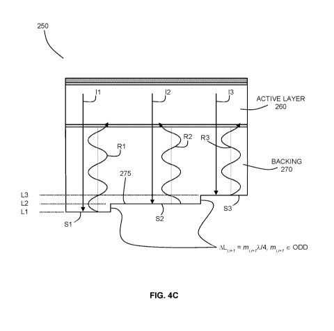
Such an example embodiment is illustrated in FIG. 4C, where example
transducer 250 includes backing 270 having segmented surface 275, where three
segments 51, S2 and S3 are laterally offset by an odd multiple of a quarter
wavelength of the propagating waveform within the backing layer. The specific
embodiment shown in the Figure illustrates the example case where the
longitudinal
spatial offset AL - X./4 (note that this Figure is not to scale). As shown in
the Figure,
R1 and R2 differ from each other by a phase delay of n. Similarly, R2 and R3
differ
from each other by a phase delay of n. This phase delay results in destructive
interference in the generation of a secondary signal, in the electrical
domain, by the
reflected waves as they propagate through active layer 260. It is therefore
apparent
that the embodiment shown in FIG. 4C reduces the impact of the reflected waves
on
artifacts generated by their passage through active layer 260, both due to the
temporal spreading of the reflected acoustic waves, and due to the
interference of
the reflected waves.
The time interval between the primary pulse and the arrival of the secondary
reverberation of the reflected signal from each level will be dependent on the
path
length associated with the backing thickness associated with the level. The
level with
the minimum path length is the level with the minimum thickness and this level
will
correspond the shortest time interval. Similarly, the level with the maximum
path
length is the level with the maximum thickness and this level will correspond
to the
longest time interval. For a short primary pulse, the pulse duration of the
secondary
reverberation pulse will be approximately the time difference between the
shortest
and longest time intervals.
As noted above, one specific example implementation involves levels with a
lateral offset of approximately X./4. This embodiment may be useful or
beneficial
when attempting to suppress reverberations from short pulses, because this
minimal
step among levels ensures that the reflected waves from adjacent levels have a
minimal relative shift in time in order to achieve efficient destructive
interference. In
other words, if the relative time delay between adjacent reflected acoustic
waves is
large (e.g. on the order of the pulsewidth, as opposed to on the order of the
period of
the fundamental frequency of the pulse), then the amplitudes of the adjacent
reflected acoustic waves may be very dissimilar and thereby prevent achieving
sufficient destructive interference, especially for the leading and trailing
edges of the
pulse where the pulse envelope varies strongly with time.
Although the configuration shown in FIG. 4C illustrates an example
embodiment in which there is one segment per level (5111, 5212, and 5313), it
is
12
CA 02930648 2016-05-13
WO 2015/074152
PCT/CA2014/051111
to be understood that this is but one example configuration, and that in other
embodiments, a given level may have two or more segments associated therewith.
In
such a case, the two or more segments associated with a given level are
approximately co-planar, such that they have a common backing thickness
associated therewith. An example of such an alternative configuration is shown
in
FIG. 4D, which illustrates an embodiment that is functionally equivalent to
that of FIG.
4C, since the segmented surface 325 is provided such that the total area of
associated with each level, which is obtained by summing the area of the
segments
making up each level, is equal for the two embodiments.
Therefore, even though the two embodiments shown in FIGS. 4C and 4D
employ different segmented surface geometries, they are expected to exhibit
similar
performance in suppressing artifacts associated with spurious reverberations
within
the transducer backing. It is noted, however, that in some embodiments and
applications, it may be beneficial to provide levels with one segment per
level, for
example, in order to simplify the cost and complexity of fabrication, and/or
to avoid or
reduce the number of intermediate longitudinal side walls that may degrade the
performance of a device due to scattering effects.
Comparing FIGS. 4C and 4B, it can be seen that the areas of the segments
forming the different levels, while being approximately equal in FIG. 4B, are
unequal
in FIG. 4C. In FIG. 4B, the levels were spatially offset in order to spread
the reflected
acoustic wave over a broader time duration, so as to produce a secondary
signal with
a reduced amplitude in receive mode. In FIG. 4C (and FIG. 4D), however,
adjacent
levels are also spatially offset by odd multiples of a quarter of the
operational
wavelength of the transducer, such that the reflected acoustic waves from
adjacent
surfaces are out of phase when they propagate through the active layer.
The reflected acoustic waves from the various segments together produce a
net response within the active layer, based on their combined effect. The
intensity of
the reflected signal from each level will be proportional to the fractional
area of the
level relative to the overall area of the backing. In one embodiment, in order
to
produce destructive interference at a given moment in time during the
propagation of
the reflected acoustic waves through the active layer, the contributions from
the
reflected acoustic waves associated with the odd numbered levels (e.g. levels
1, 3, 5,
....) and the reflected acoustic waves associated with the even numbered
levels (e.g.
levels 2, 4, 6, ....) should be approximately equal. This condition can be
met, for
example, when the total area of the odd levels is approximately equal to the
total
area of the even levels.
It will be understood that the embodiment shown in the Figures 4A-4D, which
13
CA 02930648 2016-05-13
WO 2015/074152
PCT/CA2014/051111
shows a transducer including three levels, is merely provided as an
illustrative
example, and that the number of levels may vary in other example
implementations.
For example in some embodiments, the number of spatially offset levels may be
two.
Such an embodiment may be useful, for example, in applications in which a
small
backing size is sought to support the inclusion of the transducer within a
minimally
invasive catheter, such as an ultrasonic imaging and/or therapeutic catheter
(or a
multi-modality catheter including ultrasound for one or more imaging and/or
therapeutic modalities). Moreover, it may be beneficial to employ such a low-
profile
segmented backing in applications involving narrowband acoustic signals, or,
for
example, in applications involving Doppler ultrasound. In other embodiments,
the
number of spatially offset levels may be three or more. As noted above, and
further
described below, in some embodiments, the dimensions of the transducer are
sufficiently small for use within a minimally invasive catheter (example
dimensions of
such catheters are described below).
In some embodiments, the surface areas of the levels may be provided to
compensate for depth-dependent attenuation in order to achieve suitable
interference
of reflected acoustic waves. Such depth-dependent attenuation occurs due to
the
increased propagation path length within the backing that is experienced by
acoustic
waves that are reflected by segments having larger local backing thicknesses.
For
example, if two levels are separated by a quarter of a wavelength, then the
acoustic
wave reflected from the deeper segment (having a larger local backing
thickness) will
experience a reduction in the acoustic intensity by e'2, where a is the power
attenuation coefficient of the backing, relative to the acoustic beam
reflected by the
shallower segment (having a smaller local thickness). In order to compensate
for the
intensity loss of the wave reflected from the deeper segment, the surface area
of the
deeper segment can be increased by a factor of approximately el/2 (or
equivalently,
the surface area of the shallower segment can be reduced by e-cw2). This
compensation ensures that the intensity of the two reflected and phase-shifted
acoustic waves are approximately equal, such that the two waves interfere
effectively
in the active layer.
Referring now to FIG. 4C, it can be seen that the first and third levels, L1
and
L3, respectively, have approximately equal areas, and that the second level L2
(the
middle, or intermediate level) has an area that is approximately double that
of the first
or third levels, such that the area of the second level (the only even level)
is
approximately equal to the combined area of the odd levels (the sum of the
area of
the first and third levels). As can be seen in FIG. 4C, the acoustic waves
reflected
14
CA 02930648 2016-05-13
WO 2015/074152
PCT/CA2014/051111
from levels L1 and L3 are related by a phase delay of 27r, such they add
constructively, while the acoustic wave reflected from level L2 is out of
phase with the
acoustic waves reflected from levels L1 and L3. Accordingly, the net effect of
the
various reflected acoustic waves sum within active layer 260 such that their
contributions to the generation of the secondary signal destructively
interfere.
It is noted, however, that in some embodiments that involve a backing
configured to employ interference of reflected acoustic waves, the areas of
the
segments forming the different levels may be equal, while still achieving
interference.
For example, in embodiments in which the number of levels is an even number,
the
levels may have approximately equal areas, as this would produce reflected
acoustic
waves from the even and odd levels with substantially equal contributions,
thereby
resulting in destructive interference and suppression of the secondary signal.
Accordingly, in light of the aforementioned discussion of the role of the
areas
of the segments, it will be understood that in some embodiments, the number of
different segments that are included at a given level (or are associated with
a given
backing thickness), and the areas of the segments included at a given level,
may be
chosen, designed or selected such that the weighting of the areas of the
segments
produces suitable interference of the reflected acoustic waves from the
various
levels.
The preceding embodiments show example implementations in which the
different levels of the segmented surface are separated by steep transition
walls that
are approximately perpendicular to the planes of the segments (such as
transition
wall 227 in FIG. 4A). The effects of such vertical walls will depend on the
diffusion/deflection that occurs at the vertical walls for each given
reflection from a
segmented surface and what the resultant phase relationship will be for each
portion
of the reflection that returns to the active layer. It will be understood,
however, that in
other embodiments, one or more of the transition walls may be sloped. An
example
implementation with a sloped transition wall is illustrated in FIG. 4E, where
transducer 350 has a backing surface 375 that includes sloped transition walls
380.
The sloped side walls may take on a wide variety of geometries, such as
straight
slopes as shown in FIG. 4E, or, for example, curved slopes. The geometry of
the
slope may, in some cases, be dictated by the manufacturing process, and its
inherent
tolerances. In some embodiments, sloped transition walls may be provided that
are
angled, for example, as shown in FIG. 4E, to provide anechoic surfaces that
reflect a
portion of an incident acoustic beam in a lateral direction, thereby
increasing the path
length of the reflected acoustic wave, and its associated attenuation. In some
embodiments, the side walls 382 and 384 of the backing 370 may include
additional
CA 02930648 2016-05-13
WO 2015/074152
PCT/CA2014/051111
anechoic surfaces or features.
Although the preceding embodiments illustrate examples in which the
segmented surface is a distal surface of the backing, it will be understood
that the
segmented surface may be provided or formed in any surface of the backing that
is
further from the surface proximate to the active layer. For example, in some
embodiments, the segmented surface may be formed in a further surface that is
an
internal surface within the backing. Such an internal surface separates two
different
backing layers having different acoustic impedances, such that acoustic
reflections
are generated by the internal surface.
FIG. 4F illustrates an additional example implementation of such an
embodiment, in which the segmented surface is formed in an internal surface
390
formed between first backing layer 392 and second backing layer 394. Backing
layers 392 and 394 have different acoustic impedances, such that an acoustic
reflection is generated by internal surface 390. The presence of second
backing layer
394, having a non-segmented distal surface 396, may be beneficial in reducing
or
preventing the accumulation of bubbles that may otherwise form at a segmented
distal surface.
The acoustic impedances of the layers may be selected such that the
acoustic impedance of second layer 394 is lower than that of first layer 392,
such that
the acoustic impedance mismatch between second layer 394 and the region
external
to the backing is reduced, such that reflections from surface 396 are reduced.
Surface 396 may also have a sloped or anechoic surface geometry in order to
reduce
the generation of acoustic reflections that propagate back towards the active
layer.
Second layer 394 may be formed from an attenuating backing material having a
thickness that is sufficient for substantially reducing the amplitude of
reflections from
surface 396 that propagate back through internal surface 390 (e.g. reducing
the
amplitude of reflections by 50% or more, 75% or more, 90% or more, or 95% or
more).
In some embodiments, the backing may be segmented such that the
minimum thickness segment of the backing is sufficiently thin that the
reverberation
pulse interferes with the primary pulse.
Various embodiments described herein refer to an "operational wavelength"
of a transducer. The term "operational wavelength" may be defined as described
below. When designing a piezoelectric based ultrasound transducer stack, the
thickness of the active layer is often substantially smaller than the width of
the active
layer (typically 1110th the size or smaller). This is done to separate the
frequency of
the fundamental thickness resonant mode of the layer from any lateral
resonance
16
CA 02930648 2016-05-13
WO 2015/074152
PCT/CA2014/051111
mode. Within any propagating material or medium (such as conductive silver
epoxy
or human tissue) the propagating waveform will have a fundamental wavelength
that
is related to the frequency of the fundamental resonance mode through the
speed of
sound of the material or medium, according to the relation: Wavelength = speed
of
sound / frequency. In some embodiments, the operational wavelength may be this
fundamental design wavelength.
In real transducers, materials are not perfect (ideal) resonators and
therefore
the fundamental frequency is actually a band of excited frequencies that can
be
characterized by a center frequency and a bandwidth of excited frequencies.
Matching layers and backing layers are added to effectively couple as much of
the
resonant energy out the front face of the transducer stack and into the
propagating
medium in as short a time as possible. This will result in yet a broader
frequency
response of the stack, (i.e. broader bandwidth of excited frequencies)
allowing for the
transducer stack to more closely replicate an ultrasound pulse response
waveform
from a short excitation transmit signal (say a single cycle waveform) as well
as from a
more narrow band excitation pulse such as a tone burst of several cycles in
duration.
Fabrication tolerances can also result in deviations of the time and frequency
response of the transducer. In some embodiments, the operational wavelength
associated with the transducer may be the wavelength within the frequency
response
of the stack, such as the center wavelength. For example, in some embodiments,
the
operational wavelength associated with the transducer may include any
wavelength
within this combined design, excitation pulse, and fabrication tolerance
dependent
bandwidth.
It is further noted that the residual secondary signals produced by the
reflection from the segmented surface may have an envelope such that they have
a
different frequency spectrum than the primary signal. Accordingly, in some
embodiments, any step between levels need not be exactly an odd multiple of a
quarter of an operational wavelength. In some embodiments, a given operational
wavelength corresponds to any frequency within a given percentage of the
waveform
bandwidth (such as 50% of the bandwidth), relative to the center frequency of
the
waveform. For example: for a short pulse excitation waveform with a center
frequency of 10 MHz and a bandwidth of 10 MHz, one may consider selecting the
value of the step to be an odd multiple quarter wavelength based on
frequencies
within the range of approximately 7.5 to 12.5 MHz. In other embodiments, the
selection of the height of a step may be chosen in relation to an operational
wavelength that is selected on frequencies within other ranges, such as, for
example,
frequencies within 10%, 20%, 30% or 40% of bandwidth, relative to the center
17
CA 02930648 2016-05-13
WO 2015/074152
PCT/CA2014/051111
frequency.
The backing may be formed from a wide variety of materials, including, but
not limited to, epoxy, powder loaded epoxy, porous metals, porous ceramics,
and
engineered 2-phased composite structures. In embodiments in which the phase of
the reflected acoustic waves from different segments is employed to produce
destructive interference, the backing may be formed from a material that
otherwise
would have been expected to substantially preserve the coherence of acoustic
waves
propagating therein. Examples of such backing materials include single phase
materials (epoxies, polymers, metals), powder loaded epoxies whereby the size
of
the doping particulates are not well tuned to the scattering of ultrasound at
the
operational wavelength. As noted above, the backing thickness may be such that
the
backing may not sufficiently attenuate the acoustic energy by means of
acoustic
absorption and scattering alone. The backing may be coated with a layer that
is
hydrophilic and/or electrically insulating. Non-limiting examples of suitable
coatings
include Parylene and Ti02.
Although the above embodiments disclose example transducers with a
backing having a surface that is segmented such that the segments vary along
one
dimension, it will be understood that the backing may be segmented in such
that the
segments vary in two spatial dimensions. In other words, the segmented surface
of
the backing may vary in up to three dimensions ¨ one dimension defining the
different levels, and one or two dimensions defining the variations in the
segments.
In one example implementation, at least a portion of a further surface of the
backing may be segmented into a plurality of square and/or rectangular
segments,
such that the segments vary in two dimensions. In another example
implementation,
at least a portion of a further surface of the backing may be segmented into a
series
of annular segments surrounding a central circular or elliptical segment.
It is to be understood that the phrase "segmented surface", as used herein,
refers to a further surface of a transducer backing where at least a portion
of the
further surface is segmented into segments that define three or more levels,
as
described above. In some embodiments, only a portion of the further surface is
segmented. For example, in one example implementation, the further surface of
the
backing may have one or more functional devices attached thereto over a first
portion
thereof, and the remaining portion of the further surface may be segmented as
described above. One example of a functional device attached to a portion of
the
surface of a transducer backing is an angle detection transducer, as described
in
Patent Cooperation Treaty Patent Application No. PCT/CA/2012/050057, titled
"ULTRASONIC PROBE WITH ULTRASONIC TRANSDUCERS ADDRESSABLE ON
18
CA 02930648 2016-05-13
WO 2015/074152
PCT/CA2014/051111
COMMON ELECTRICAL CHANNEL" and filed on January 31st, 2012, which is
incorporated herein by reference in its entirety.
In some embodiments, the segmented surface is configured to suppress
secondary signals generated by the reflection of short pulses, such as pulses
having
an envelope with a time duration approximately equal to approximately 1 cycle,
two
cycles, or three cycles. For example, a typical medical imaging pulse is a
short pulse
in time that may last for 1-2 cycles (1-2 wavelengths) or more. The envelope
of a
short time pulse waveform can be considered to have a rising, or positive,
slope and
followed, shortly thereafter, by a falling, or negative, slope. This is in
contrast to a
tone burst of several wavelengths where the envelope of such a pulse waveform
would be characterized by an initial rising slope with a segment of a
substantially flat
envelope of zero slope followed by a final falling slope.
In one embodiment, in order to suppress the effect of the rising and falling
edges of a reflected signal, the segmented surface may be formed as a
plurality of 'n'
stepped segments, whereby each adjacent segment creates an approximately
additional 1/2 of an operational wavelength delay in the signal such that the
leading
and trailing edge of the signal is reduced to 1/n in strength and the
contributions from
all intermediate reflected signals cancel destructively. Such an embodiment is
illustrated in Example 1 below.
In one embodiment, the segmented surface may be defined as follows. A first
set of segments is defined by two adjacent segments, longitudinally offset by
approximately a quarter of an operational wavelength of the transducer,
thereby
defining two levels of the segmented surface. An additional portion of the
segmented
surface is then formed by cloning the first set of segments, and offsetting
the cloned
set by approximately a quarter of an operational wavelength (with m = 1) of
the
transducer.
An example implementation of this method of defining a segmented surface is
shown with reference FIGS. 5A and 5B, which show the backing portion of a
transducer. In FIG. 5A, segmented surface 405 of backing 400 is formed from
four
segments, defining levels L1-L4, where each level has a common surface area,
and
each level is stepped and shifted from another by a quarter of an operational
wavelength of the transducer. In contrast, FIG. 5B shows a backing 450 having
a
segmented surface 455 that is defined based on the cloning and shifting of
first set of
segments 460. Specifically, second set of segments 470 is a copy of first set
of
segments 460 that has been shifted upward by a quarter of an operational
wavelength of the transducer.
This method of defining a segmented surface by cloning and offsetting may
19
CA 02930648 2016-05-13
WO 2015/074152
PCT/CA2014/051111
be repeated more than once. An example embodiment of a segmented surface
formed from three cloning and shifting operations is shown in FIG. 5C.
Segmented
surface 505 of backing 500 is formed by multiple cloning and shifting
operations to
define second, third and fourth sets of segments 470, 472 and 474 from first
set of
segments 460.
In another embodiment, a segmented surface can be defined by the following
double cloning and shifting method. One or more cloning and shifting
operations may
be performed to define a first segmented surface portion, which may be
referred to
as a superset of segments. One or more cloning and shifting operations are
then
performed using the superset of segments to define a segmented surface
including
at least one additional superset of segments that is cloned and shifted
relative to the
first superset of segments.
An example implementation of this embodiment is shown in FIG. 5D, in a
superset of surfaces is cloned and shifted to produce segmented surface 555 of
backing 550. This segmented surface is produced by cloning and shifting first
superset 560 to obtain second superset of surfaces 570. As seen in the Figure,
superset 570 which is shifted by a quarter of an operational wavelength
relative to
first superset 560. First superset of surfaces 560 is itself obtained by the
cloning and
shifting operation shown in FIG. 5B.
As described above, the spatial distribution of segments associated with a
given level (or local backing thickness) can be varied, and one segment can be
divided into several segments having an equivalent total area, since the
amplitude of
the secondary pulse is the sum across the entire area of the electrode. This
is
illustrated in FIG. 5E, which shows backing 575 having segmented surface 580
for
which the areas of the segments at each level are equal to those in FIG. 5D,
such
that segmented surface 580 is functionally equivalent to segmented surface 555
of
FIG. 5D.
Accordingly, it should be understood that spatial permutations of one-
dimensional or two-dimensional segments can be categorized by the extent to
which
the full energy content of the initial wave transmitted into the backing, is
cancelled,
due to phase interference by the various reflections off of the bottom surface
of the
backing layer and can be expressed in terms of the reduction of the intensity
of any
secondary signal and its relation to the intensity of the primary pulse.
It will be understood that the aforementioned method of cloning and shifting a
superset may also be performed one or more additional times to define surfaces
with
additional levels and complexity. For example, backing 600 of FIG. 5F shows a
segmented surface 605 that has been defined based on a cloning and shifting
CA 02930648 2016-05-13
WO 2015/074152
PCT/CA2014/051111
operation in which the first superset 610 is taken to be the segmented surface
shown
in FIG. 5D. Superset 610 is cloned and shifted to obtain additional surface
portion
620. The resulting complex segmented surface is functionally equivalent to
segmented surface 655 of backing 650 that is shown in FIG. 5G.
The simulated performance of cloned and segmented surfaces, relative to
stepped surfaces, is illustrated in FIGS. 6A and 6B. In FIG. 7A, various
secondary
signal waveforms are shown that compare stepped segmented surfaces, such as
the
stepped surface shown in FIG. 5A, to the secondary signal obtained from a flat
(control) surface, based on a realistic waveform with a short pulse envelope
having a
time duration of approximately three cycles. As can be seen from the Figure,
the
amplitude of the secondary signals is reduced, but remains appreciable, for
all
segmented surfaces, with the best performance obtained for the 5-level stepped
segmented surface. The incomplete cancellation of the secondary waveform based
on destructive interference can be understood to occur because of the rapid
variations in the amplitude of the pulse waveform at the leading and trailing
edges of
the pulse. These contributions of these edges to the secondary signal are not
cancelled due to the equal weighting of reflected components for all levels
that arises
from the common surface area of the levels.
In contrast, FIG. 7B shows the improved cancellation that occurs for
segmented surfaces that are defined by the cloning and shifting method
described
herein. The Figure shows the broad cancellation of the secondary signal
obtained
from segmented surfaces based on the single clone and shift surface of FIG.
5B, and
the superset-based clone and shift operation shown in FIG. 5D.
FIG. 7B therefore shows that in the case of short pulses, the nulling of the
secondary signal can be improved by defining a segmented surface according to
the
cloning and shifting method described above. However, it will be understood
that a
more general prescription may also be employed to obtain similar results. This
more
general prescription can be understood by examining the progression of the
total
surface area for the levels, which is shown in FIGS. 5E and 5G, which shown
segmented surfaces that are functionally equivalent to the segmented surfaces
shown in FIGS. 5D and 5F, respectively. The segmented surface shown in FIG. 5E
is
characterized by per-level surface areas that vary, in units of the surface
area of the
first level, as follows: 1 (L1), 3 (L2), 3 (L3) and 1 (L4). Similarly, the
segmented
surface shown in FIG. 5G is characterized by per-level surface areas that
vary, in
units of the surface area of the first level, as follows: 1 (L1), 4 (L2), 6
(L3), 4 (L4), and
1 (L5).
These segmented surfaces are characterized by per-level surface areas that
21
CA 02930648 2016-05-13
WO 2015/074152
PCT/CA2014/051111
monotonically increase to one or more intermediate levels, and then
monotonically
decrease. It is also apparent that for each level between the first level and
the one or
more intermediate levels, there exists an associated level with an
approximately
equal surface area that resides between the one or more intermediate levels
and the
final level.
Accordingly, one prescription for defining a segmented surface involves
providing a segmented surface characterized by per-level surface areas that
monotonically increase to one or more intermediate levels, and then
monotonically
decrease. The segmented surface may further be characterized such that for
each
level between the first level and the one or more intermediate levels, there
exists an
associated level with an approximately equal surface area that resides between
the
one or more intermediate levels and the final level. Although the example
embodiments shown in the Figures illustrate segmented surfaces for which the
per-
level surface areas are related by a whole-number multiplier, it is understood
that this
is not a general requirement, and that in other embodiments, two or more of
the per-
level surface areas may be related by numbers other than whole numbers. As
described above, the surface areas of the various levels may be defined to
compensate for depth-dependent attenuation in order to achieve suitable
interference
of reflected acoustic waves.
Ultrasonic transducers, and backings for ultrasonic transducers as disclosed
in the preceding embodiments, may be fabricated according to various
processes.
One example method for forming a segmented backing surface is to employ
standard
transducer processing equipment to segment the backing into several steps.
These
steps may be separated by transition walls as described above, and may be
machined using equipment such as a dicing saw. The width of the steps can be
controlled by the width of the blade and the index step of the dicing saw
machine.
Other material removal processes are also conceived such as CNC
machining or laser machining. The use of a 3, 4, or 5 axis CNC machine could
be
employed to provide transition walls that are more tapered in nature.
Similarly, laser
machining may be employed to control the wall profile, as the laser spot
typically
removes just a small amount of material per laser pulse and thus provides for
fine
control over the geometrical profile of the surface of the backing.
Although the images presented are for single element transducers, this
technique can also be applied to annular, linear and phased arrays of 1D,
1.25D,
1.5D, 1.75D, and 2D arrayed devices as well as well as sparsely populated
arrays.
FIG. 6 shows an example of an ultrasonic array 700 including an array of
transducers
705, each having a backing having a further surface 710 that is segmented over
at
22
CA 02930648 2016-05-13
WO 2015/074152
PCT/CA2014/051111
least a portion thereof (the Figure shows the example case of the further
surface
being the distal surface of the backing).
It will also be understood that the transducer stack design may also contain
more than one active layer. The polarization of the active layers be polarized
in the
same orientation or in opposite orientation. Any transducer type that utilizes
a
backing layer can be modified according to the embodiments provided in the
present
disclosure to reduce or modify the effects of reverberation within the backing
layer
itself.
In some embodiments, the devices described herein may be employed as
ultrasound transducers in minimally invasive ultrasound applications such as
imaging
and/or therapeutic catheters. Non-limiting examples of such minimally invasive
ultrasound catheters having ultrasonic transducers that may be modified to
include a
segmented backing include those described in United States Patent No.
8,460,195,
titled "SCANNING MECHANISMS FOR IMAGING PROBE", and filed on March 27,
2009, which is incorporated herein by reference in its entirety, and in Patent
Cooperation Treaty Patent Application No. PCT/CA/2012/050057, as referenced
above. Useful ultrasound frequencies for catheters typically lie in the 5-100
MHz
range. The size of vessels where a catheter may be useful will result in
catheters of
approximately 2-15 French. Assuming a typical backing like conductive epoxy
(with a
speed of sound of 1950 m/s) and a reasonable number of segment levels to be in
the
range of 4-6 levels, then the stack thickness for a 10 MHz PZT transducer
could be
kept to within a total thickness of approximately 600 microns. The use of
materials
with a relatively slow speed of sound, such as rubber materials, having a
speed of
sound on the order of 1000-1500 m/s, would lead to minimum thicknesses of
about
400 microns. Depending on the nature of the distal housing that holds the
transducer
inside the sheath of the catheter, a 60 MHz transducer of reasonable axial
imaging
capability could be assembled and realized inside an approximately 2 Fr
catheter or
smaller.
It will be understood that embodiments of the present disclosure that permit a
reduction in the backing thickness may be employed in a wide variety of
ultrasound
applications in which limited space is available for the transducer. Such
embodiments
may be useful, for example, applications in which the ability to place an
ultrasound
transducer in close proximity to tissue allows for the use of higher frequency
ultrasound to image the regions of interest for improved imaging resolution.
Therefore intracardiac imaging, intravascular imaging, needle based and
endoscopic
applications such as bladder and other urethral imaging applications or
auditory
imaging applications can benefit from this disclosure respectively. Although
many of
23
CA 02930648 2016-05-13
WO 2015/074152
PCT/CA2014/051111
the examples provided herein relate to medical ultrasonic transducers and
medical
applications involving ultrasonic transducers, such as ultrasonic imaging
transducers
and ultrasonic therapeutic devices, it will be understood that various
embodiments of
the present disclosure may be employed in other applications and fields. For
example, ultrasonic transducers having segmented backing according to the
preceding embodiments may be employed for applications such as no-contact
sensing, motion sensors, flow sensing, non-destructive testing, range finding,
location sensing, and communications. They can also be used to reduce the
pulse
duration of energy delivered during therapeutic ultrasound, such as High
Intensity
Focused Ultrasound (HIFU).
The following examples are presented to enable those skilled in the art to
understand and to practice embodiments of the present disclosure. They should
not
be considered as a limitation on the scope of the disclosure, but merely as
being
illustrative and representative thereof.
EXAMPLES
Example 1: Modelling of Secondary Signal Produced by Reflection of Single
Cycle Pulse
A mathematical model was employed to demonstrate the effect of different
segmented profiles on a primary signal consisting of a single cycle pulse. A
number
of different segmented profiles were modeled, and the resulting secondary
signals
are shown in FIG. 8. The model shows how various portions of the reflected
pulse
are removed via destructive interferences caused by the reflected waves, and
how
some residual portions of the reflected pulse that are not removed are
decreased in
amplitude due to the temporal spreading of the reflected pulse.
FIG. 8 shows four different secondary signals (the primary signal is not
shown), corresponding to different profiles of the distal surface of the
backing. The
thick solid Black line shows the secondary signal that is produced by a
backing of
uniform thickness 'T'. This curve is merely a reproduction of the primary
pulse. This
secondary signal is referred to below as the "control" secondary signal.
The dashed light grey line shows the secondary signal obtained from a two-
level segmented backing consisting of two segments of equal area, where the
first
segment is of thickness 'T' and the second is of thickness 'T + X/4' where X
is the
wavelength of the center frequency of the acoustic wave propagating within the
backing layer. The resulting secondary signal is a double pulse shape, where
the
pulses are 1/2 of the signal intensity of the control secondary signal
obtained from the
flat surface. The secondary signal in this example is extended in time by an
extra 1/2
period. The two reflected acoustic waves that form the secondary signal are
phase-
24
CA 02930648 2016-05-13
WO 2015/074152
PCT/CA2014/051111
shifted by 180 degrees, such that when one signal has a maximum positive
intensity,
the other signal has a maximum negative intensity and when summed, the
portions
of the signal that overlap cancel. The leading half wave section of the
reflected signal
from the shorter segment and the trailing half wave section of the reflected
signal
from the longer segment remain. They do not cancel and they are each 1/2 the
intensity of the leading and trailing sections of the control secondary signal
with a
separation gap of 1/2 wavelength.
The dashed dark grey line shows the reflected signal from a backing of
variable thickness where there are five segments of equal area where the first
segment is of thickness 'T' and the additional four segments are each of and
additional thickness equal to 'T + N(X/4)' where N = 1..4 relative to the
thinnest
segment. This curve shows that increasing the number of segments results in a
longer separation between the residual peaks, and increased attenuation of the
residual peaks. The number of segments can be increased, to further minimize
the
peak intensity and to further lengthen the pulse duration of the secondary
pulse,
which may be done at the expense of increased fabrication complexity.
The dotted light grey line shows the secondary signal obtained for a
transducer having a backing with a segmented distal surface having 21
segments,
where the segments are each of additional thickness equal to 'T + N(X/80)',
and
where N = 1..20 relative to the thinnest segment (for a total thickness
variation of a
quarter of a wavelength). This example segmented surface represents an
approximation of a wedge shaped backing, where the backing is linearly
increasing in
thickness. While this approach provides the benefit of reducing the amplitude
of the
secondary signal via the spreading out of the secondary signal over an
increased
time duration, the amplitude of the secondary signal remains appreciable.
The dotted dark grey line shows the secondary signal obtained for a
transducer having a backing with a segmented distal surface having 81
segments,
where the segments are each of additional thickness equal to 'T + N(X/80)',
and
where N = 1..80 relative to the thinnest segment (for a total thickness
variation of one
wavelength). The portions of the leading and trailing slopes that are not
fully
cancelled have partially spread. The peak of the residual rising and falling
slopes are
actually a little lower than the peaks from the segmented approach.
Example 2: Mathematical Model and Experimental Demonstration of
Suppression of Secondary Signal in Transducer Having Backing with
Segmented Distal Surface
In the present example design, a transducer with a segmented backing was
CA 02930648 2016-05-13
WO 2015/074152
PCT/CA2014/051111
fabricated, and the acoustic response was experimentally measured and
mathematically modeled. FIG. 9 is an illustration of the segmented backing of
the
transducer design. As shown in the Figure, the example transducer is a single-
element transducer with a polygonal aperture, having a backing layer 800 that
is
segmented into seven levels (L1-L7), where the areas of the various segments
are
equal. The active and matching layers are not shown in the Figure. The section
820
to the right of the dark band is not active. The distal surface of the backing
layer
includes the segmented surface define by the segments forming the seven levels
L1-
L7, and two additional base regions 805 and 810 of the backing at the upper
and
lower ends thereof. The thickness of the backing is thicker at the top and
bottom of
the device and thinnest in the middle.
A transducer stack, designed for a center frequency of 10 MHz, was
fabricated with a 5H type PZT as the active layer, a 400 um layer of silver
epoxy as
the backing and silver epoxy and non-conductive epoxy as the respective
matching
layers. The backing of the transducer was then diced into segments as per FIG.
9,
using a conventional dicing saw. Mounting the transducer into a fixture, the
device
could be placed in a water tank and excited with a single cycle transmit
pulse. With a
hydrophone the one-way waveform along the principle axis of the transducer
could
be measured. Two-way measurements measured off of a flat plastic surface were
also taken.
A one-way signal (or response) is a signal that is the result of being
converted
through the active piezoelectric layer of the transducer once. For example: If
a
transmitted acoustic signal is detected from a transducer using an acoustic
sensor
such as a hydrophone, then the detected hydrophone signal is a one-way signal.
A
two-way signal (or response) is a signal that is the result of being converted
through
the active piezoelectric layer of the transducer twice. For example, when the
same
transducer is used to acoustically transmit an electric drive signal and then
in turn is
used to sense the reflected transmitted acoustic signal from the medium, then
the
detected electrical signal by the transducer is a two-way signal.
The one-way and two-way measurements were obtained for the transducer
prior to, and after, forming the segmented layer. The strength of the
secondary
signals with and without the segmented surface were compared, as shown in
FIGS.
10A and 10B, respectively (the x-axis is in samples (with a sample period of 5
nsec ¨
sampling rate of 200 MHz). The amplitude of the one-way signal was reduced by
about 16.5 dB and the 2-way was reduced by about 20 dB.
A linear propagation model simulation tool (K-wave found at http://www.k-
wave.org/index.php) was also employed to model the acoustic response of the
26
CA 02930648 2016-05-13
WO 2015/074152
PCT/CA2014/051111
transducer. The single element transducer was modeled with a 12.5 MHz center
frequency, and the silver epoxy backing layer had a thickness of approximately
450
microns. The simulated primary signal used to drive the transducer was
compared to
the simulated reflected signal from a segmented patterned backing (the backing
was
generated in 3D CAD), providing simulated one-way results. The secondary
pulses
predicted by the mathematical model are shown in FIG. 3 (planar backing) and
FIG.
11 (segmented backing). It was found that the transmitted electrical pressure
of the
secondary signal was reduced by approximately 19 dB when the segmented backing
was employed.
The specific embodiments described above have been shown by way of
example, and it should be understood that these embodiments may be susceptible
to
various modifications and alternative forms. It should be further understood
that the
claims are not intended to be limited to the particular forms disclosed, but
rather to
cover all modifications, equivalents, and alternatives falling within the
spirit and scope
of this disclosure
27