Note: Descriptions are shown in the official language in which they were submitted.
CA 02930672 2016-05-20
VARIABLE STIFFNESS COMPRESSION APPARATUS, SYSTEMS AND METHODS OF
USING THE SAME
TECHNICAL FIELD
[0001] The present invention comprises an apparatus for use in line with a
chain or a strap
tie-down assembly. When the chain or strap tie-down assembly is tightened on a
commodity to
prevent movement of the same during shipping, the apparatus compresses and
stretches. During
transport, if the commodity loosens and creates slack in the chain or tie-down
assembly, the
apparatus may decompress and shorten, thereby taking up the slack and
maintaining tension in the
chain or tie-down assembly to prevent or minimize loosening and damage of the
commodity.
BACKGROUND
[0002] Commodities are often transported from one location to another,
especially via train
lines or vehicles. Often, it is important to ensure that the commodities are
effectively secured
during transport to minimize movement of the commodities. Specifically, a
railcar experiences
lateral, longitudinal, and even vertical movement as the railcar travels. For
example, railcars are
typically coupled together, and this coupling may cause the railcars to jostle
and move erratically.
In addition, as a train travels from one location to another, railcars may
experience erratic
movement, such as when a train accelerates and decelerates, and further due to
irregularities in the
track. Thus, commodities that are not tied down securely may also move or
become jostled,
causing damage to the commodities.
[0003] Chains and other tie-down assemblies, including links, carabineers,
ratchets, and other
like apparatuses are typically utilized to attempt to ensure that commodities
are tied down securely
during transport of the same. Often, chains and/or other tie-downs are either
linked to the railcar or
vehicle itself and wrapped around the commodity, or linked directly to the
commodity and to the
CA 02930672 2016-05-20
=
railcar or vehicle. It is a goal to tie-down the commodity so that the
commodity does not move
during shipment.
[0004] However, it is often the case that despite the attention to tying
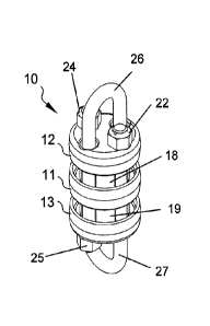
down the commodities
using chains and/or tie-down assemblies, commodities may shift during
transport, which may lead
to the development of slack in the chain or tie-down assembly. In such a
situation, the commodity
may be subject to additional movement or jostling during shipment, potentially
leading to damage
of the commodity.
[0005] A need, therefore, exists for an apparatus that may take up loose
slack of chains and
tie-down assemblies. Specifically, a need exists for an apparatus to take up
loose slack of chains
and tie-down assemblies during shipment of a commodity tied down by the chains
or tie-down
assemblies.
[0006] Moreover, a need exists for an apparatus that may effectively be
compressed and
elongated during compression. Specifically, a need exists for an apparatus
that may decompress
and shorten when slack develops in a chain or tie-down assembly.
[0007] In addition, a need exists for an apparatus that may compress and
elongate, and
decompress and shorten and having significant strength to withstand
substantial compression
forces. Moreover, a need exists for an apparatus utilized to take up slack in
a chain or tie-down
assembly that may be easily linked in-line with the chain or tie-down
assembly.
[0008] Heretofore, it is known to utilize compression elements in chains or
tie-down
assemblies that may compress or decompress based on tension applied or
unapplied, respectively.
However, prior solutions have limited application because only single
compressible non-metallic
material is used leading to a compressible material that is constant as
opposed to variable. This
2
CA 02930672 2016-05-20
severely limits the properties of the compression apparatus. A need,
therefore, exists for a
compression apparatus that may be tailored to specific needs. More
specifically, a need exists for a
compression apparatus that has variable stiffness elements so that the
compression apparatus may
have better applicability in different tie-down situations.
SUMMARY OF THE INVENTION
[0009] The present invention comprises an apparatus for use in line with a
chain or a strap
tie-down assembly. When the chain or strap tie-down assembly is tightened on a
commodity to
prevent movement of the same during shipping, the apparatus compresses and
stretches. During
transport, if the commodity loosens and creates slack in the chain or tie-down
assembly, the
apparatus may decompress and shorten, thereby taking up the slack and
maintaining tension in the
chain or tie-down assembly to prevent or minimize loosening and damage of the
commodity.
[0010] To this end, in an embodiment of the present invention, a
compression apparatus is
provided. The compression apparatus comprises: a body formed by a first U-
shaped bolt and a
second U-shaped bolt disposed in an inverted position relative to the first U-
shaped bolt, the body
having a first end and a second end, wherein a first cap is disposed at the
first end, a second cap is
disposed at the second end and a first internal space is disposed between the
first cap and the
second cap, wherein legs of the first U-shaped bolt are disposed through the
first cap and the
second cap and further wherein the legs of the first U-shaped bolt are rigidly
held to the second cap,
wherein legs of the second U-shaped bolt are disposed through the second cap
and the first cap and
further wherein the legs of the second U-shaped bolt are rigidly held to the
first cap; a first
compressible material within the first space between the first cap and the
second cap; wherein the
first compressible material has first and second internal elements, wherein
the first internal element
3
CA 02930672 2016-05-20
contributes to the compressibility of the compression apparatus at a first
force applied to the
compression apparatus and further wherein a combination of the first internal
element and the
second internal element contributes to the compressibility of the compression
apparatus at a
second force applied to the compression apparatus.
[0011] In an embodiment, the first and second internal elements have
different stiffness
constants.
[0012] In an embodiment, wherein the legs of at least the first U-shaped
bolt and the second
U-shaped bolt are threaded.
[0013] In an embodiment, the legs of the first U-shaped bolt and the second
U-shaped bolt are
threaded, and further wherein the legs of the first U-shaped bolt and the
second U-shaped bolt are
rigidly held to the second and first caps, respectively, with nuts.
[0014] In an embodiment, the first internal element is longer in length
than the second internal
element and fills more of the first internal space between the first and
second caps than the second
internal element.
[0015] In an embodiment, the first internal element has an open volume
therein, and the second
internal element is disposed within the open volume within the first internal
element.
[0016] In an embodiment, the first internal element has the same stiffness
constant as the
second internal element.
[0017] In an embodiment, the first internal element has a different
stiffness constant as the
second internal element.
[0018] In an embodiment, the compression apparatus further comprises: a
center guide plate
disposed between the first cap and the second cap forming the first internal
space between the first
4
CA 02930672 2016-05-20
cap and the center guide plate and a second internal space between the second
cap and the center
guide plate.
[0019] In an embodiment, the compression apparatus further comprises: a
second compressible
material disposed within the second internal space between the second cap and
the center guide
plate, wherein the second compressible material comprises a first internal
element and a second
internal element, wherein the first internal element of the second
compressible material contributes
to the compressibility of the compression apparatus at the first force applied
to the compression
apparatus and further wherein a combination of the first internal element and
the second internal
element of the second compressible material contributes to the compressibility
of the compression
apparatus at the second force applied to the compression apparatus.
[0020] In an alternate embodiment of the present invention, a system is
provided. The system
comprises the compression apparatus further comprising: a first tie-down
element extending from
the first U-shaped bolt.
[0021] In an embodiment, the first tie-down element is a chain.
[0022] In an embodiment, the system further comprises: an item to be tied
down, wherein the
first tie-down element secures the item and prevents movement during transport
thereof.
[0023] In an embodiment, the system further comprises: a first tie-down
element extending
from the first U-shaped bolt; and a second tie-down element extending from the
second U-shaped
bolt.
[0024] In an embodiment, the first and second tie-down elements are chains.
[0025] In an embodiment, the system further comprises: an item to be tied
down, wherein at
least one of the first and second tie-down elements secures the item and
prevents movement during
CA 02930672 2016-05-20
transport thereof.
[0026] In an alternate embodiment of the present invention, a method of
securing an item for
transport is provided. The method comprises the steps of: providing an item to
be secured for
transport; providing a tie-down element and securing the item with the tie-
down element;
connecting a compression apparatus to the tie-down element, said compression
apparatus
comprising a first internal element and a second internal element, wherein the
first internal element
contributes to the compressibility of the compression apparatus at a first
force applied to the
compression apparatus and further wherein a combination of the first internal
element and the
second internal element contribute to the compressibility of the compression
apparatus at a second
force applied to the compression apparatus; applying a first force to the
compression apparatus,
wherein the compression apparatus has a first compressibility at the first
force; and applying a
second force to the compression apparatus, wherein the compression apparatus
has a second
compressibility at the second force that is a combination of the stifthess
constants of the first and
second internal elements.
[0027] In an embodiment, the first tie-down element is secured to a first
end of the compression
apparatus.
[0028] In an embodiment, the method further comprises the steps of:
providing a second
tie-down element; and securing the second tie-down element to the compression
apparatus.
[0029] In an embodiment, the second tie-down element is secured to a second
end of the
compression apparatus.
[0030] It is, therefore, an advantage and objective of the present
invention to provide an
apparatus that may take up loose slack of chains and tie-down assemblies.
6
CA 02930672 2016-05-20
[0031] Specifically, it is an advantage and objective of the present
invention to provide an
apparatus to take up loose slack of chains and tie-down assemblies during
shipment of a
commodity tied down by the chains or tie-down assemblies.
[0032] Moreover, it is an advantage and objective of the present invention
to provide an
apparatus that may effectively be compressed and elongated during compression.
[0033] Specifically, it is an advantage and objective of the present
invention to provide an
apparatus that may decompress and shorten when slack develops in a chain or
tie-down assembly.
[0034] In addition, it is an advantage and objective of the present
invention to provide an
apparatus that may compress and elongate, and decompress and shorten that is
significantly strong
to withstand significant compression forces.
[0035] Moreover, it is an advantage and objective of the present invention
to provide an
apparatus utilized to take up slack in a chain or tie-down assembly that may
be easily linked in-line
with the chain or tie-down assembly.
[0036] In addition, it is an advantage and objective of the present
invention to provide a
compression apparatus that may be tailored to specific needs.
[0037] More specifically, it is an advantage and objective of the present
invention to provide a
compression apparatus that has variable stiffness elements so that the
compression units may have
better applicability in different tie-down situations.
[0038] Additional features and advantages of the present invention are
described in, and will be
apparent from, the detailed description of the presently preferred embodiments
and from the
drawings.
7
CA 02930672 2016-05-20
BRIEF DESCRIPTION OF THE DRAWINGS
[0039] The drawing figures depict one or more implementations in accord
with the present
concepts, by way of example only, not by way of limitations. In the figures,
like reference numerals
refer to the same or similar elements.
[0040] FIG. 1 illustrates an isometric view of a variable stiffness
compression apparatus in an
embodiment of the present invention.
[0041] FIG. 2 illustrates an isometric view of a variable stiffness
compression apparatus in a
compressed and elongated state in an embodiment of the present invention.
[0042] FIG. 3 illustrates a top view of a variable stiffness compression
apparatus in an
embodiment of the present invention.
[0043] FIG. 4 illustrates an exploded isometric view of a variable
stiffness compression
apparatus in an embodiment of the present invention.
[0044] FIG. 5 illustrates a sectional view of a variable stiffness
compression apparatus in an
uncompressed and shortened state in an embodiment of the present invention.
[0045] FIG. 6 illustrates a sectional view of a variable stiffness
compression apparatus in a
semi-compressed and semi-elongated state in an embodiment of the present
invention.
[0046] FIG. 7 illustrates a sectional view of a variable stiffness
compression apparatus in a
compressed and elongated state in an embodiment of the present invention.
[0047] FIG. 8 illustrates a perspective view of a variable stiffness
compression apparatus
in-line with first and second chains in an embodiment of the present
invention.
8
CA 02930672 2016-05-20
DETAILED DESCRIPTION OF THE PRESENTLY PREFERRED EMBODIMENTS
[0048] The present invention comprises an apparatus for use in line with a
chain or a strap
tie-down assembly. When the chain or strap tie-down assembly is tightened on a
commodity to
prevent movement of the same during shipping, the apparatus compresses and
stretches. During
transport, if the commodity loosens and creates slack in the chain or tie-down
assembly, the
apparatus may decompress and shorten, thereby taking up the slack and
maintaining tension in the
chain or tie-down assembly to prevent or minimize loosening and damage of the
commodity.
[0049] Now referring to the figures, wherein like numerals refer to like
parts, FIG. 1 illustrates
an isometric view of a preferred embodiment of the present invention of a
compression apparatus
in its normal, non-elongated static state. The apparatus may comprise a first
U-bolt 26 and a
second U-bolt 27 inverted with respect to the first U-bolt 26, with the first
and second U-bolts 26,
27 disposed in proximity to each other at roughly ninety degrees to each
other.
[0050] A first end cap 12 may be disposed at a top end of the apparatus 10
and a second end cap
13 may be disposed on a bottom end of the apparatus 10. A center guide plate
11 may be disposed
at a midpoint between the top end and the bottom end of the apparatus 10. The
first and second
U-bolts may traverse through each of the first and second end caps 12, 13 and
the center guide plate
11, thereby maintaining the U-bolts in relative positions to each other. Nuts
22, 24 and 23, 25 may
hold the U-bolts in place in their relative positions, and may be tightened
onto first and second end
caps 12, 13 respectively.
[0051] A first internal element 18 may be disposed between first end cap 12
and center guide
plate 11, and a second internal element 19 may be disposed between center
guide plate 11 and the
second end cap 13. The first and second internal elements 18, 19 may be made
from a
9
CA 02930672 2016-05-20
compressible material that may shorten and fill the internal space between the
first and second end
caps 12, 13 and the center guide plate 11 when compressed by tension forces,
as described below.
[0052] In use, the apparatus 10 may be disposed in-line with one or more
chains or tie-down
assemblies. Specifically, a first chain or tie-down (not shown) may be linked
to the first U-bolt 26
and a second chain or tie-down (not shown) may be linked to the second U-bolt
27. Thus, the
apparatus 10 may directly bear the tension of the chain or tie-down assembly
when used to
tie-down a commodity.
[0053] As illustrated in FIG. 2, the apparatus 10 is shown in a partially
or semi-elongated state.
Specifically, as stress on the apparatus 10, by tension forces 14, 15 applied
to first and second
U-bolts 26, 27, the end caps 12, 13 may be forced to travel with their
respective U-bolt in
respective directions 26, 27. For example, as tension is applied to the first
and second U-bolts 26,
27, end cap 12 may travel with U-bolt 27, and end cap 13 may travel with U-
bolt 26. Thus, as
tension increases on the first and second U-bolts 26, 27, end caps 12, 13 may
travel towards center
guide plate 11. This action may compress the internal elements 18, 19,
respectively, and reduce the
gaps 28, 29 (as shown in FIG. 5).
[0054] FIG. 3 illustrates a top view of the apparatus 10, showing nuts 22,
24 that may be
installed on the end of the U-bolt 27, thereby aiding in holding the apparatus
10 assembly together.
Internal elements 18, 20 are illustrated in hidden lines to illustrate their
respective relationship with
other parts.
[0055] FIG. 4 illustrates an exploded isometric view of the apparatus 10.
The legs of the first
and second U-bolts 26, 27 may be inserted through their respective end caps
12, 13. A round and
preferably solid, non-metallic element 20 may be disposed in a central hole of
the element 18, and
CA 02930672 2016-05-20
=
this sub-assembly is assembled along the legs of the U-bolt 26. Likewise, the
round, preferably
solid cylindrical element 21 may be disposed in the central hole of the
element 19, and this
sub-assembly may be assembled along the legs of U-bolt 27. The legs of the
first and second
U-bolts 26, 27 may be inserted through the appropriate holes in the center
guide plate 11 and
further inserted through the other parts, such as the first and second end
caps 12, 13, until the
threaded ends of the U-bolts 26, 27 protrude through the end caps 12, 13
allowing nuts 22, 24 and
23, 25, respectively, to be installed onto the threaded ends of the U-bolts
26, 27. The nuts 22, 24
and 23, 25, respectively, may effectively hold the apparatus 10 together and
prevent it from coming
apart. The shape, size and material of the internal components, such as the
internal elements 18, 19
and the elements 20, 21, respectively, may be specifically tailored to
accommodate the desired
performance characteristics of the apparatus 10.
[0056] The internal elements 18, 19 and the elements 20, 21 may be disposed
together,
respectively, to provide a compression material having a variable stiffness.
Preferably, the internal
elements 18, 19 and the elements 20, 21 may be made from a solid, non-metallic
material, such as
thermoplastic or rubber. Preferably, the compression material describe herein
has a memory such
that, when compressed, the compression material deforms but when compression
is removed, the
compression material returns to its original shape and size. Thus, the
compression material as
described herein acts as a spring that may allow the apparatus 10 to deform
when compressed, but
return to its original size and shape when compression forces are decreased or
removed.
[0057] FIGS. 5-7 illustrate sectional views of the apparatus 10 progressing
from a
non-compressed state (FIG. 5) to a partially compressed and partially
elongated state (FIG. 6) to a
fully compressed and elongated state (FIG.7). As illustrated in FIG. 5, the
round preferably solid
11
CA 02930672 2016-05-20
cylindrical non-metallic elements 20, 21 may be shorter in length than the
internal elements 18, 19.
Although the elements 20, 21 are shown as round or cylindrically-shaped, it
should be noted that
the elements 18, 19 may be any shape so as to accommodate the performance
variation of the
application desired. As illustrated in FIG. 5, because the elements 20, 21 are
shorter than internal
elements 18, 19, a space may be formed between surface 30 of element 20 and
surface 32 of the end
cap 12. Likewise, a space may be formed between surface 31 of element 21 and
surface 33 of the
end cap 13.
[0058] FIG. 6 illustrates apparatus 10 in a partially compressed and
partially elongated state,
when tension forces 14, 15 are applied to first and second U-bolts 26, 27 in
the directions shown in
FIG. 6. As tension forces 14, 15 are applied, surfaces 30, 31 for the elements
20, 21, respectively,
come into contact with surfaces 32, 33 of the first and second end caps, 12,
13, respectively,
thereby eliminating the spaces therebetween. The result of this action may
compress the internal
elements 18, 19 only and not the elements 20, 21, which may result in the
forces 14, 15 being
dependent and directly proportional to the inherent compression stiffness k2,
k 1 , respectively, of
the elements 18, 19 only. As the apparatus 10 elongates, the gaps 28, 29 are
reduced to form
reduced gaps 34, 35, as shown in FIG. 6. The reduced gaps 34, 35 may also
serve as a visual
indicator of the compression and elongation of the apparatus 10.
[0059] As the apparatus 10 is compressed into its fully compressed and
fully elongated state, as
shown in FIG. 7, forces 38, 39 pull on first and second U-bolts 26, 27. As the
apparatus 10 is fully
elongated, further compression of the elements 18, 19 along with compression
of the elements 20,
21 results. Thus, the compression of the apparatus 10 may be dependent upon a
combination of the
inherent stiffnesses (k2, k4 and kl, k3, respectively) of internal elements
18, 19 and elements 20,
12
CA 02930672 2016-05-20
21, respectively. Moreover, fully compressing and fully elongating the
apparatus 10 reduces gaps
34, 35 (as illustrated in FIG. 6) to fully reduced/closed gaps 36, 37 (as
shown in FIG. 7). As the
apparatus 10 elongates from a partially compressed and partially elongated
state (as illustrated in
FIG. 6) to a fully compressed and fully elongated state (as illustrated in
FIG. 7), the apparatus 10
performs differently due to the combination of inherent stiffness constants of
the internal elements
18, 19 and elements 20, 21, respectively. Thus, depending on the performance
characteristics
desired, one may change the performance characteristics of the apparatus 10 by
changing the
shapes, sizes and materials of internal elements 18, 19 and elements 20, 21,
respectively.
[0060] For example, while the preferred embodiment of the present invention
shows internal
elements 18, 19 and elements 20, 21, which may be incorporated within elements
18, 19
respectively, additional or different elements may be utilized to change the
compression and
elongation features of the apparatus 10. In one embodiment, each internal
element utilized may
have the same stiffness constant, but may engage and contribute to the overall
compressibility of
the compression apparatus at different forces applied to the compression
apparatus. Alternatively,
each internal element utilized may have a different stiffness constant, and
thus contribute to the
overall compressibility of the compression apparatus differently than the
other elements. In either
case, the differences between the internal elements allow for variable
compression of the
compression apparatus at different force applied thereto.
[0061] For example, as described herein, because the elements 20, 21 are
shorter than the
internal elements 18, 19, the stiffness constants of the elements 20, 21
(labeled k2, kl, respectively)
do not contribute to the compressibility of the compression apparatus 10 until
the space within
reaches a pre-determined level, and the end caps 12, 13 begin compressing the
elements 20, 21.
13
CA 02930672 2016-05-20
Therefore, for a portion of the compression of the apparatus 10, only the
internal elements 18, 19
contribute to the compressibility thereof. As the tension forces increase, the
stiffness constant
combination of the internal elements 18, 19 and the elements 20, 21 (k2, k4
and k 1 , k3,
respectively) contribute to the compressibility of the apparatus 10. This may
be useful in a
situation, for example, such as when a relatively low stiffness is desired for
a first amount of
tension applied to the compression apparatus, but a higher degree of stiffness
is desired for a
second amount of tension applied to the compression apparatus.
[0062] In another embodiment of the present invention, a compression
apparatus (not shown)
have only have a single internal space between a first end cap and a second
end cap, without a
center guide plate at a midpoint between ends of the compression apparatus.
Thus, the internal
space may have a compression material having two or more internal elements
that contribute to the
compressibility of the compression apparatus at different applied forces, as
described above.
Likewise, it is contemplated that two or more center guide plates may be
provided to provided
additional internal spaces, which may or may not contain additional
compression materials for
contributing to the compressibility of a compression apparatus, as described
herein.
[0063] FIG. 8 illustrates a system of the present invention of the
apparatus 10 used in-line with
a first chain 50 and a second chain 52. Specifically, U-bolt 26 may be
interconnected with a link of
the first chain 50 and U-bolt 27 may be interconnected with a link of the
second chain 52 and
disposed in-line between the first and second chains 50, 52 to tie a commodity
(not shown) down,
as disclosed above. A cotter pin 40 may be disposed on ends of the legs of the
U-bolts 26, 27 to
provide security, preventing the removal of the nuts disposed thereon.
[0064] It should be noted that various changes and modifications to the
presently preferred
14
CA 02930672 2016-05-20
embodiments described herein will be apparent to those skilled in the art.
Such changes and
modifications may be made without departing from the spirit and scope of the
present invention
and without diminishing its attendant advantages. Further, references
throughout the specification
to "the invention" are nonlimiting, and it should be noted that claim
limitations presented herein
are not meant to describe the invention as a whole. Moreover, the invention
illustratively disclosed
herein suitably may be practiced in the absence of any element which is not
specifically disclosed
herein.