Note: Descriptions are shown in the official language in which they were submitted.
1
ARC BAFFLING DEVICE
BACKGROUND
Field
The disclosed concept pertains generally to electrical switching apparatus
and, more
particularly, to arc baffling devices for use in such switching apparatus.
Background Information
Electrical switching apparatus, such as circuit breakers, provide protection
for
electrical systems from electrical fault conditions such as, for example,
current overloads, short
circuits, and abnormal level voltage conditions.
Circuit breakers, for example, typically include a set of stationary
electrical contacts
and a set of movable electrical contacts. The stationary and movable
electrical contacts are in physical
and electrical contact with one another when it is desired that the circuit
breaker energize a power
circuit. When it is desired to interrupt the power circuit, the movable
contacts and stationary contacts
are separated. Upon initial separation of the movable contacts away from the
stationary contacts, an
electrical arc is formed in the space between the contacts. The arc provides a
means for smoothly
transitioning from a closed circuit to an open circuit, but produces a number
of challenges to the
circuit breaker designer. Among such challenges is the fact that the arc
results in the undesirable flow
of electrical current through the circuit breaker to the load. Additionally,
the arc, which extends
between the contacts, often results in vaporization or sublimation of the
contact material itself.
Therefore, it is desirable to dissipate and extinguish any such arcs as soon
as possible upon their
propagation.
To facilitate this process, circuit breakers typically include arc chute
assemblies which
are structured to attract and break-up the arcs. Specifically, the movable
contacts of the circuit breaker
are mounted on arms that are contained in a pivoting assembly which pivots the
movable contacts past
or through arc chutes as
3450331
CA 2930860 2019-10-07
CA 02930860 2016-05-16
WO 2015/073136
PCT/US2014/059588
- 2 -
they move into and. out of electrical contact with the stationary contacts.
Each are
chute includes a plurality of spaced apart arc plates mounted in a wrapper. In
operation, as the movable contact is moved away from the stationary contact,
the
movable contact moves past. the ends of the arc plates, with the arc being
magnetically
drawn toward and between the arc plates. The arc plates are electrically
insulated
from one another such that the arc is broken-up and extinguished by the arc
plates.
Examples of arc chutes are disclosed in U.S. Pat. Nos. 79034,242; 6,703,576;
and
6,297,465.
Additionally, along with the generation of the arc itself, ionized gases,
which can cause excessive heat and additional arcing and, therefore, are
harmfid to
electrical components, are formed as a byproduct of the arcing event. The
ionized
gases produced during an arcing event can undesirably strike to the ground and
create
ground fault issues. Additionally, debris, such as, for example, molten metal
particles
or plasma, may be created during the arcing event and thus may be readily
transported
by the ionized gases. The uncontrolled release of such ionized gases and
molten
particles can be extremely harmful to components and/or personnel positioned
nearby
the circuit breaker during an arcing event.
There is a need, therefore, to provide mechanisms which control and defuse the
ionized gases and plasma before leaving the housing of the circuit breaker.
Accordingly, there is room for improvement in arc baffles for arc chute
assemblies, and in arc chute assemblies for electrical switching apparatus,
such as
circuit breakers.
SUMMARY
These needs and others are met by embodiments of the disclosed
concept, which provides for controlling and cooling of the ionized plasma as
it exits
an arc chute.
in accordance with one aspect of the disclosed concept, an arc baffle
comprises: a first baffle member having a number of first venting holes
disposed
therein, each of the first venting holes being structured to receive ionized
gases
produced by an arcing event; a second baffle member having a number of second
venting holes disposed therein; a section of porous material disposed between
the first
baffle member and the second baffle member; and a cover disposed adjacent the
CA 02930860 2016-05-16
WO 2015/073136
PCT/US2014/059588
- 3 -
second baffle member on the opposite side of the section of porous material,
the cover
having a number of openings disposed adjacent the second venting holes. The
first
venting holes are laterally spaced from the second venting holes by a
predetermined
distance such that ionized gases produced by the arcing event passing through
one of
the first venting holes must travel at minimum the predetermined distance
generally
along the section of porous material before passing through one of the second
venting
holes.
The number of first venting holes may be disposed offset from a
centerline of the first baffle member toward a first end thereof and the
number of
second venting holes may be disposed offset from a centerline of the second
baffle
member toward a second end thereof.
Each of the first baffle member and the second baffle member may be
of generally planar shape.
The section of porous material may comprises a plurality of generally
planar mesh screens.
'The plurality of generally planar mesh screens may be disposed
generally parallel with respect to, and between, the first baffle member and
the second
baffle member.
Each of the mesh screens may be formed from steel and glass
reinforced polyester.
The cover may include a cavity portion disposed on an underside
thereof adjacent the number of openings and the second baffle member and the
section of porous material may be housed within the cavity portion.
The first baffle member may be coupled. to the cover via a number of
fasteners.
The cover may further include a number of tabs structured to engage
corresponding apertures formed in portions of an arc chute.
In accordance with another aspect of the disclosed concept, an arc
chute comprises: a first sidewall; a second sidewall., a plurality of
electrically
conductive arc plates disposed between, and supported by the first sidewall
and the
second sidewall, the plurality of electrically conductive arc plates being
structured to
attract an arc produced by an arcing event resulting from the separation of
electrical
CA 02930860 2016-05-16
WO 2015/073136
PCT/US2014/059588
- 4 -
contacts disposed adjacent thereto; and an arc baffle disposed adjacent the
plurality of
electrically conductive arc plates. The arc baffle comprises: a first baffle
member
having a number of first venting boles disposed therein, each of the first
venting holes
being structured to receive ionized gases produced by the arcing event; a
second
baffle member having a number of second venting holes disposed therein; a
section of
porous material disposed between the first baffle member and the second baffle
member; and a cover disposed adjacent the second baffle member on the opposite
side
of the section of porous material, the cover having a number of openings
disposed
adjacent the second venting holes. The first venting holes are laterally
spaced from
the second venting holes by a predetermined distance such that ionized gases
produced by the arcing event passing through one of the first venting holes
must
travel at minimum the predetermined distance generally along the section of
porous
material before passing through one of the second venting holes.
The cover may further include a number of tabs extending from
opposing sides thereof, the first sidewall may include a first aperture, the
second
sidewall may include a second aperture, and the cover may be coupled to the
first
sidewall and the second sidewall via engagement of the tabs with the first and
second
apertures.
The number of first venting holes may be disposed offset from a
centerline of the first baffle member toward a first end thereof and the
number of
second venting holes may be disposed offset from a centerline of the second
baffle
member toward a second end thereof.
Each of the first baffle member and the second baffle member may be
of generally planar shape.
The section of porous material may comprise a plurality of generally
planar mesh screens.
The plurality of generally planar mesh screens may be disposed
generally parallel with respect to, and between, the first baffle member and
the second
baffle member.
The cover may include a cavity portion disposed on an underside
thereof adjacent the number of openings, and the second baffle member and the
section of porous material may be housed within the cavity portion.
CA 02930860 2016-05-16
WO 2015/073136
PCT1US2014/059588
- 5 -
The first baffle member may be coupled. to the cover via a number of
fastenets.
In accordance with yet another aspect of the disclosed concept, an
electrical switching apparatus comprises: separable electrical contacts
disposed within
a housing and an arc chute disposed adjacent the separable electrical
contacts. The
arc chute comprises: a first sidewall; a second sidewall; a plurality of
electrically
conductive arc plates disposed between, and supported by the first sidewall
and the
second sidewall, the plurality of electrically conductive arc plates being
structured to
attract an are produced by an arcing event resulting from the separation of
the
electrical contacts disposed adjacent thereto; and an arc baffle disposed
adjacent the
plurality of electrically conductive arc plates. The arc baffle comprises: a
first baffle
member having a number of first venting holes disposed therein, each of the
first
venting holes being structured to receive ionized gases produced by the arcing
event;
a second baffle member having a number of second venting holes disposed
therein;
a section of porous material disposed between the first baffle member and the
second
baffle member; and a cover disposed adjacent. the second baffle member on the
opposite side of the section of porous material, the cover having a number of
openings
disposed adjacent the second venting holes_ The first venting holes are
laterally
spaced from the second venting holes by a predetermined distance such that
ionized
gases produced by the arcing event passing through one of the first venting
holes must
travel at minimum the predetermined distance generally along the section of
porous
material before passing through one of the second venting holes.
The cover may further include a number of tabs extending from
opposing sides thereof, the first sidewall may include a first aperture, the
second
sidewall may include a second aperture, and the cover may be coupled to the
first
sidewall and the second sidewall via engagement of the tabs with the first and
second
apertures.
The:cover May father include an opening and the arc baffle may be
coupled to the housing via a fastener disposed in the opening.
Each of the first baffle member and the second baffle member may be
of generally planar shape and the section of porous material may comprise a
plurality
CA 02930860 2016-05-16
WO 2015/073136
PCT/US2014/059588
- 6 -
of generally planar mesh screens disposed generally parallel with respect to,
and
between, the first baffle member and the second baffle member.
The cover may include a cavity portion disposed on an underside
thereof adjacent the number of openings, the second baffle member and the
section of
porous material may be housed within the cavity portion, and the first baffle
member
may be coupled to the cover via a number of fasteners.
These and other objects, features, and characteristics of the disclosed
concept, as well as the methods of operation and functions of the related
elements of
structure and the combination of parts and economies of manufacture, will
become
more apparent upon consideration of the following description and the appended
claims with reference to the accompanying drawings, all of which form a part
of this
specification, wherein like reference numerals designate corresponding parts
in the
various figures. It is to be expressly understood, however, that the drawings
are for
the purpose of illustration and description only and are not intended as a
definition of
the limits of the disclosed concept.
BRIEF DESCRIPTION OF THE DRAWINGS
A hill understanding of the disclosed concept can be gained from the
following description of the preferred embodiments when read in conjunction
with the
accompanying drawings in which:
FIG. I is a cross-sectional view of a portion of a circuit breaker,
including an arc chute assembly having an arc baffle in accordance with an
embodiment of the disclosed concept.
FIG. 2 is an isometric view of a portion oldie circuit breaker of FIG.
I with the arc chute assembly shown exploded from the circuit breaker.
FIG. 3, 4 and. 5, respectively, are top , side and bottom views of the
arc baffle of FIGS. I and 2.
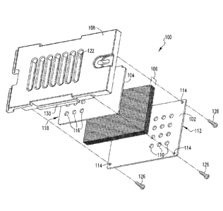
FIG. 6 is an exploded isometric view of the arc baffle of FIGS. 1-5.
FIG. 7 is a detailed cross-sectional view of a portion of the circuit
breaker of FIG. I taken along another section of the circuit breaker showing
details
of the arc baffle and flow of ionized gases relative thereto.
CA 02930860 2016-05-16
WO 2015/073136
PCT/US2014/059588
- 7 -
DESCRIPTION OF THE PREFERRED EMBODIMENTS
For purposes of illustration, embodiments of the disclosed concept will
be described as applied to arc chute assemblies for molded case circuit
breakers,
although it will become apparent that they could also be applied to a wide
variety of
electrical switching apparatus (e.g., without limitation, circuit switching
devices and
other circuit interrupters, such as contactors, motor starters, motor
controllers and
other load controllers) having an arc chute.
Directional phrases used herein, such as, for example, left, right, top,
bottom, front, back and derivatives thereof, relate to the orientation of the
elements
shown in the drawings and are not limiting upon the claims unless expressly
recited
therein.
As employed herein, the statement that two or more parts are
"coupled" together shall mean that the parts are joined together either
directly or
joined through one or more intermediate parts.
As employed herein, the term "ionized" means completely or partially
converted into ions and being at least somewhat electrically conductive such
as, for
example, ionized gases generated by arcing between separable electrical
contacts of a
circuit breaker when opened.
As employed herein, the term "number" shall mean one or an integer
greater than one (i.e., a plurality).
As employed herein, the term "fastener" refers to any suitable
connecting or tightening mechanism expressly including, but not limited to,
screws,
bolts, nuts (e.g., without limitation, lock nuts) and combinations thereof.
As employed herein, the term "laterally spaced" means separated by a
distance toward a side of the object. In instances where two objects lying in
different
generally parallel planes are said to be "laterally spaced", such spacing
shall refer to
the distance between such objects if superimposed on a single plane.
FIG. 1 shows a portion of an electrical switching apparatus, such as a
circuit breaker 2, including a housing 4, separable contacts 6,8 (e.g.,
stationary contact
6 and movable contact 8), enclosed by the housing 4, and an operating
mechanism 10
(shown in simplified form in FIG. I) structured to open and close the
separable
contacts 6,8. Specifically, the operating mechanism 10 is structured to trip
open the
CA 02930860 2016-05-16
WO 2015/073136
PCT/US2014/059588
- 8 -
separable contacts 6,8 in response to an electrical fault (e.g.õ without
limitation, an
overcurrent condition, an overload condition, an undervoltage condition, or a
relatively -hiult level short circuit or fault condition). When the separable
convicts 6,8
trip open, an arc 12 is generated. The circuit breaker 2 includes at least one
arc chute
assembly 20 disposed at or about the separable contacts 6,8 in order to
attract and
dissipate the arc 12.
Referring to FIG. 2 in addition to FIG. I, each arc chute assembly 20
includes first and second opposing sidewalls 22,24 (e.g., made of a suitable
non-
conductive composite material) and a plurality of electrically conductive arc
plates 30
(only two are labeled in FIG. 2) (e.g., without limitation, nickel plated;
1010 magnetic
steel plates) disposed between, and supported by the first and second opposing
sidewalls 22,24. More specifically, each of the first and second opposing
sidewalls
22,24 of the arc chute assembly 20 includes a plurality of apertures 26928
(shown only
on first opposing sidewall 22 of FIG. 2), and each arc plate 30 includes a
number of
protrusions 32,34 (shown only in first opposing sidewall 22 of arc chute
assembly 20
of FIG. 2) extending outward therefrom. The apertures 26,28 of the first and
second
opposing sidewalls 22,24 each receive the protrusions 32,34 of a corresponding
one of
the arc plates 30. It is to be appreciated that arc plates 30 are structured
to generally
attract an arc produced by separation of contacts 6 and 8 through any known
means
and that the general structure of the arc plates 30 and sidewalls 22,24 of arc
chute
assembly 20 is provided for example purposes only and is not intended to be
limiting
upon the disclosed concept. Instead, it is to be appreciated that embodiments
of the
disclosed concept may be generally employed with arc chute assemblies of
various
constructions. U.S. Patent Nos. 7,034,242 and 7,674, 996, .lbr example,
without
limitation, provide non-limiting examples of arc chute assemblies generally
suitable
for use in accordance with embodiments of the disclosed concept.
In order to control and defuse ionized gases created by an arcing event
before exiting housing 4 of the circuit breaker .2, arc chute assembly 20
further
includes an arc baffle 100 for defusing and selectively discharging ionized
gasses
(generally indicated by the arrows 16 in FIGS. .1 and 7) from the housing 4
produced
as a byproduct of the arc 12 (FIG. 1). Referring to FIGS. 3-6, arc baffle 100
includes
a first baffle member 102, a second baffle member 104, a section of porous
material
9
106 disposed between the first, baffle member and the second baffle member
104, and a cover 108. In
the illustrated example embodiment, the first arc baffling member 102 and the
second arc baffle
member 104 are comprised of machined are and track resistant insulating
reinforced thermoset
polyester, however other suitable materials may be employed without varying
from the scope of the
disclosed concept.
Referring to FIGS. 5-7, first baffle member 102 is of generally planar shape
and
includes a number of first venting holes 110 (three are labeled in FIGS. 5 and
6) disposed therein in a
first grouping offset from a centerline (not numbered) of the first baffle
member 102 toward a first end
112 thereof. Although twelve first venting holes 110 of circular shape are
illustrated (arranged in three
rows of four), it is to be appreciated that one or more of the quantity, size,
or arrangement of the first
venting holes may be varied (as long as such venting holes are generally
disposed toward first end
112) without varying from the scope of the disclosed concept. As shown in FIG.
6, first baffle member
102 further includes a number of mounting apertures 114 for coupling first
baffle member 102 to
cover 108, as discussed in greater detail below.
Referring to FIGS. 3, 6 and 7, second baffle member 104 is also of generally
planar
shape and includes a number of second venting holes 116 (three are labeled in
FIGS. 3 and 6) disposed
therein in a second grouping offset from a centerline (not numbered) of the
second baffle member 104
toward a second end 118 (FIGS. 6 and 7) thereof. Although twelve second
venting holes 116 of
circular shape are illustrated (arranged in three rows of four), it is to be
appreciated that one or more of
the quantity, size, or arrangement, of the second venting holes may be varied
(as long as such venting
holes are generally disposed toward second end 118) without varying from the
scope of the disclosed
concept.
Referring to FIGS. 6 and 7, the section of porous material 106 is formed from
a
number of generally planar mesh screens 120 (e.g., without limitation, formed
from steel woven cloth
or other suitable material) stacked together to a predetermined thickness (not
labeled). The thickness
of the section of porous material may be selectively varied in order to
accommodate with voltage and
current rating of the circuit, associated therewith. As best shown in the
sectional view of FIG. 7, in the
particular example embodiment illustrated in the FIGS., six layers of
individual mesh
3450331
CA 2930860 2019-10-07
CA 02930860 2016-05-16
WO 2015/073136
PCT/1152014/059588
- 10 -
screens 120 formed from steel woven cloth are employed in order to meet the
requirements for the particular application. Such steel cloth may be plated or
stainless.
Cover 108 may be formed via a molding process (e.g., without
limitation, made of a suitable insulating material, such as, for example,
glass filled
.. polyester). Referring to FIGS. 3, 6 and 7, cover 108 includes a number of
openings
122 (seven are shown in the example illustrated embodiment) which may be of
slotted
or of other suitable shape or shapes through which gases (such as shown by
arrows 16
in FIGS. 1 and 7) produced by an arcing event may be vented, as discussed
flutter
below. Cover 108 further includes a cavity portion 124 (FIG. 7) disposed on an
underside (not numbered) thereof adjacent the plurality of openings 122. As
shown in
the detailed sectional view of FIG. 7, cavity portion 124 is generally sized
and
adapted to house the second baffle member 104 as well as the section of porous
material 106 therein. The second baffle member 104 and the section of porous
material 106 are constrained in the cavity portion 124 by the first baffle
member 102
.. which is coupled to the cover 108 via a number of fasteners 126 which
engage the
first baffle member 102 about each of the mounting apertures 114.
Continuing to refer to FIG. 7, when assembled as arc baffle 100, the
first and second baffle members 102 and 104 are arranged such that the
grouping of
first venting holes 110 of the .first baffle member 102 are laterally spaced
from the
grouping of second venting holes 116 of the second baffle member 104 by a
predetermined distance d based on the particular application, thus forcing any
ionized
gases 16 produced by an arcing event within the circuit breaker to travel at
minimum
the predetermined distance d. generally along the section of porous material
106
before exiting the circuit breaker through one of openings 122 in cover 108.
As the
ionized gases 16 pass through the porous material 106 they are effectively
diffused by
providing a longer path and cooling of the ionized plasma, and any debris,
such as, for
example, molten metal particles or plasma, contained therein is also
effectively
trapped before exiting through any of openings 122 of cover 108.
As shown in FIG. 2, the arc baffle 100 is coupled in the arc chute 20 to
the plurality of arc plates 30 via tabs 130,132 which extend from opposing
sides of
cover 108 and engage the first and second opposing sidewalls 22,24 of arc
chute
assembly 20 at respective openings in each of sidewalls 22,24 (only the
opening 134
CA 02930860 2016-05-16
WO 2015/073136
PCT/US2014/059588
-
of sidewall 22 is shown in FIG. 2). As shown in FIGS. I and 7, through such
coupling the first baffle member 102 is structured to be disposed at or about
the ends
(not numbered) of arc plates 30 opposite from the ends disposed near the fixed
and
movable contacts 6, 8. As shown in FIGS. 2, 3 and 5, cover 108 may further
include
one or more openings 140 which cooperatively receive a fastener 142 (FIG. 2)
to
retain the arc chute assembly 20 to a circuit breaker housing (e.g., 4 of
FIGS. I and 2).
While specific embodiments of the disclosed concept have been
described in detail, it will be appreciated by those skilled in the art that
various
modifications and alternatives to those details could be developed in light of
the
overall teachings of the disclosure. Accordingly, the particular arrangements
disclosed are meant to be illustrative only and not limiting as to the scope
of the
disclosed concept which is to be given the full breadth of the claims appended
and
any and all equivalents thereof