Note: Descriptions are shown in the official language in which they were submitted.
CA 02930995 2016-05-25
TITLE
Apparatus and Method For The Detection Of Leaks In A Sealed Container
FIELD
This invention relates to both an apparatus and a method for the detection of
leaks in a sealed container, and in one particular embodiment to an apparatus
and method for the detection of leaks in the covers or lids of single serving
beverage capsules or cartridges.
BACKGROUND
Single serving beverage capsules or cartridges for use in beverage preparation
machines are becoming increasingly popular. Such capsules come in a variety
of forms for use in the preparation of beverages that include espresso coffee,
drip coffee, tea, hot chocolate, soups, etc. In one version, the capsules have
a
single chamber commonly defined by a plastic or aluminum body having an
open top enclosed with a cover formed from a foil, plastic or other polymer.
Typically, the chamber is filled with infusion ingredients, such as ground
coffee,
for producing beverages in a beverage machine. Hot water is injected by the
beverage preparing machine into the chamber containing the infusion
1
CA 02930995 2016-05-25
ingredients, causing the beverage to flow from the capsule into a user's cup
or
other reservoir.
In the case of single chamber beverage capsules such as those described
above, the cover is commonly glued and/or heat sealed to the upper rim of the
container. The cover thus seals the contents within the capsule and is
pierceable to permit the beverage machine to insert a probe or other device
through the cover so that water can be injected into the interior of the
chamber. In order to retain the freshness and to prevent spoilage of the
ingredients retained within the chamber, the seal between the cover material
and the upper rim of the capsule must be of a high integrity. An inferior or
incomplete seal may result in a degradation of the freshness of the
ingredients,
the infiltration of contaminants into the chamber and/or a potential loss of a
portion of the capsule's ingredients.
During the manufacturing process for capsules of the above nature, it is thus
desirable to perform at least periodic inspections in order to confirm the
integrity of the seal of the lid or cover. For many applications a periodic
testing
and statistical analysis is sufficient. However, in other instances the
particular
material retained within the capsule, its inherent value, and its likelihood
to
suffer spoilage if exposed to the environment, may necessitate a complete
testing of all capsules on an assembly line.
2
CA 02930995 2016-05-25
Others have proposed a wide variety of different methods to test for leaks in
such containers, and in particular, leaks in the seal between the upper rim of
the container or capsule and its cover or lid. Where the capsule contains dry
goods (for example coffee, tea, hot chocolate, etc.) there will also be air or
other gas present within the sealed chamber. Even where the capsule contains
a liquid, there will typically be some degree of air or gas at the top of the
container. In such cases a common method for leak detection is to submerge
sealed capsules into a water tank and observe any bubbles emanating from the
containers. Bubbles from the container will indicate the escape of gas through
a breach. Although this method of water testing can be relatively simple and
effective, it is slow and laborious and is impractical to conduct on a large
scale
or on the entire production of capsules or containers.
Water testing is
therefore, for the most part, restricted to a random sampling and a
statistical
analysis applied to the results of that random sampling. Further, while such
methods will generally identify leaks, they do little to indicate the position
or
precise location of the leak. Since most of the capsules or containers in the
nature of those described above are formed, filled and sealed on an assembly
line, the location of a particular leak can be important for troubleshooting a
potential problem in the manufacturing process. A leak at the same particular
location on multiple capsules may indicate a problem in the sealing stage of
the
assembly process (for example a lack of sufficient heat at a particular
location,
the lack of an adequate application of adhesive, etc.).
3
CA 02930995 2016-05-25
Although a significant use for such capsules is in the beverage making
industry,
there are a wide variety of other applications of sealed containers for which
leak
testing is desirable. Many of those applications are in the food industry
where
products such as juices, individual fruit or dessert servings, yogurt,
individual
cheese packages, etc. are often stored in containers or capsules having a
hermetically sealed and flexible lid or cover. Capsules or containers where a
high integrity seal is often required are also used in the pharmaceutical
industry, as well as a number of other industries.
Accordingly, there is constantly the need for new methods and devices to
assist
in the detection of leaks in hermetically sealed containers.
SUMMARY
In one aspect there is provided an apparatus for the detection of a leak
between a container and a flexible cover secured about an opening in the
container, the apparatus comprising:
a vacuum chamber for receiving the container;
a pressure indicating sensor coupled to a controller; and
a sensor support, said sensor positioned on said sensor support wherein, in
operation, said sensor is located in close proximity to the container cover
such
that when the container is within said vacuum chamber and subjected to a
4
CA 02930995 2016-05-25
vacuum condition, gases within the container cause the cover to expand at the
location of a leak between the cover and the container whereby the cover
contacts said sensor, upon contact with the cover said sensor generating a
signal received by the controller to indicate both the detection and the
location
of the leak about the opening in the container.
In another aspect there is provided a method for the detection of a leak
between a container and a flexible cover secured to a rim about an open top of
the container, the method comprising:
(i) locating the container within a vacuum chamber;
(ii) positioning a pressure indicating sensor in close proximity to at
least the
portion of the cover that is secured to the rim of the container;
(iii) establishing a pre-determined vacuum pressure within the vacuum
chamber; and
(iv) detecting contact between a portion of the cover adjacent to the upper
rim of the container and the pressure indicating sensor, said contact
indicating
an expansion in the container cover at said point of contact resulting from
the
passage of gas from within the container through a leak between the cover and
the rim of the container.
5
CA 02930995 2016-05-25
In another aspect there is provided an apparatus for the detection of a leak
between a container and a flexible cover secured about an opening in the
container, or a leak within the flexible cover, the apparatus comprising:
a vacuum chamber for receiving the container, said vacuum chamber
comprising a manufacturing line element in an assembly line for the production
of single serving beverage containers;
one or more pressure indicating sensors coupled to a controller; and
one or more sensor supports, said one or more sensors positioned on said one
or more sensor supports,
wherein, in operation, said one or more sensors are located in close proximity
to the cover, when the container is within said vacuum chamber and subjected
to a vacuum condition gases within the container cause the cover to expand
whereby the cover contacts said one or more sensors, upon contact with the
cover said one or more sensors generating one or more signals received by the
controller, said controller calculating a contact pressure between said one or
more sensors and the cover and comparing said contact pressure to a per-
determined pressure to indicate the presence of a leak.
In another aspect there is provided a method for the detection of a leak
between a container and a flexible cover secured to a rim about an open top of
the container, or a leak in the flexible cover, the method comprising:
6
CA 02930995 2016-05-25
(I) locating the container within a vacuum chamber;
(ii) positioning one or more pressure indicating sensors in close proximity
to
the cover;
(iii) establishing a pre-determined vacuum pressure within the vacuum
chamber; and
(iv) detecting contact between the cover and the one or more pressure
indicating sensors, upon contact said one or more sensors generating one or
more pressure signals received by a controller, said controller comparing said
one or more pressure signals with a predetermined value, whereby said
generated one or more pressure signals being less than said predetermined
value indicating a leak between the cover and the rim of the container, a leak
within the cover or a leak within the container.
Further aspects of the invention will become apparent from the following
description taken together with the accompanying drawings.
BRIEF DESCRIPTION OF THE DRAWINGS
For a better understanding of the present invention, and to show more clearly
how it may be carried into effect, reference will now be made, by way of
example, to the accompanying drawings which show exemplary embodiments
of the present invention in which:
7
CA 02930995 2016-05-25
Figure 1 is a side perspective view of a typical or representative single
serving
beverage capsule.
Figure 2 is a vertical sectional view through a leak detection apparatus
constructed in accordance with an embodiment of the invention.
Figure 3 is a sectional view taken along the line 3-3 of Figure 2.
Figure 4 is a plan view of an embodiment of a film sensor for use in the
apparatus of Figure 2.
Figure 5 is an enlarged detail view of portion "A" of Figure 2 prior to the
operation of the leak detection apparatus.
Figure 6 is an enlarged detail view similar to Figure 5 during operation of
the
apparatus wherein no leak is being detected in the seal between the beverage
capsule rim and the capsule's cover.
Figure 7 is an enlarged detail view similar to Figure 6 wherein a leak is
being
detected at a portion along the rim of the beverage capsule.
Figure 8 is a plan view of the baffle for use in the apparatus, designed to
simultaneously test a plurality of capsules.
Figure 9 is a schematic view of an assembly line for single serving beverage
capsules that incorporates a dedicated leak detection stage.
8
CA 02930995 2016-05-25
Figure 10 is a view similar to Figure 9 wherein the leak detection stage is
incorporated into the capsule sealing stage.
Figure 11 is a schematic view of an alternate form of assembly line to that
shown in Figure 9.
Figure 12 is an alternate embodiment to that shown in Figures 6 and 7.
Figure 13 shows still a further alternate embodiment of the invention wherein
the sensor is a displacement sensor.
DESCRIPTION
The present invention may be embodied in a number of different forms. The
specification and drawings that follow describe and disclose some of the
specific
forms of the invention.
In the following description, and in the accompanying drawings, the apparatus
and method of the present invention is described in so far as it relates to a
single serving beverage capsule, such as those that are used in the
preparation
of coffee, tea, hot chocolate and other types of infusion beverages. However,
one of ordinary skill in the art will appreciate from a thorough understanding
of
the invention that the inventive apparatus and method could equally be used on
any one of a wide variety of other sealed capsules, cartridges or containers.
9
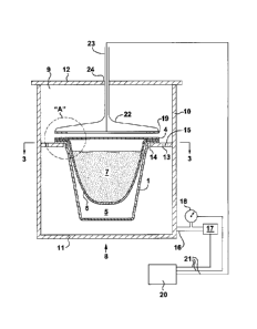
CA 02930995 2016-05-25
For illustration purposes, Figure 1 shows a relatively standard single serving
beverage capsule 1. Capsule 1 is comprised generally of a rigid or semi-rigid
body 2 having an open top circumscribed by an upper rim 3. A cover or lid 4 is
secured to rim 3, typically through the use of adhesives and/or heat sealing
means. In most instances rim 3 and cover 4 are circular in shape.
As is shown in Figure 2, body 2 forms an ingredients chamber 5 that typically
includes a filter 6 forming a pocket or receptacle into which one or more
ingredients (for example coffee grounds, ground tea, etc.) are received. The
edge of the filter may be placed over rim 3 with the combination of cover 4,
filter 6 and rim 3 adhered together. Alternately, filter 5 may be secured to
an
interior facing surface of body 2 or cover 4.
In accordance with one embodiment of the invention there is provided an
apparatus 8 for the detection of a leak between rim 3 and cover 4. Apparatus 8
includes a vacuum chamber 9 that may have a variety of different
configurations. In the attached drawings chamber 9 includes side walls 10, a
bottom 11 and a removable and sealable top 12. It will be appreciated from a
thorough understanding of the invention that top 12 can be removed or
"opened" to allow access to the interior of chamber 9 to insert and/or
retrieve
capsules 1. In one embodiment, chamber 9 includes a horizontal baffle 13
having an opening 14 to receive and support capsule 1 through the resting of
rim 3 upon the upper surface of the baffle. The baffle will act as a capsule
or
CA 02930995 2016-05-25
specimen support and also preferably includes a series of pressure equalizing
holes or openings 15 to equalize the pressure above and below the baffle when
the baffle is supporting a capsule. Interior of chamber 9 is connected via a
conduit 16 to a vacuum pump 17 that is operable to initially draw vacuum upon
the interior of chamber 9, and to subsequently re-pressurize a chamber if
required (in some cases chamber 9 may simply include a valve to permit
exterior air to be drawn into the chamber to re-pressurize it). A pressure
gauge
18 may be present to provide a visual indication of the pressure or extent of
the
vacuum within chamber 9.
Apparatus 8 further includes a pressure indicating sensor 19 that is coupled
to a
controller 20. In the embodiment of the invention shown, sensor 19 is a
tactile
pressure indicating sensor film or a pieozoelectric film sensor. Coupling of
the
sensor to the controller may be through the use of electrical conductors 21.
Conductors 21 may also be used to couple pressure gauge 18 and vacuum
pump 17 to the controller.
In one embodiment film sensor 19 will generally have a shape that is
complimentary to that of rim 3 (i.e. both the rim and the sensor may be
generally circular). The sensor may effectively be of a size and shape that is
essentially the same as that of the entirety of cover 4 or, in an alternate
embodiment, the sensor may be smaller than the cover such that it is interior
to rim 3. In a further alternate embodiment the film sensor could be of a size
11
CA 02930995 2016-05-25
that is greater than that of rim 3 so that a single sensor could be used to
monitor multiple capsules or specimens. In the embodiment shown in Figure 4,
the sensor is in the form of a ring which is generally sized and configured to
be
of a shape and dimension such that the sensor can be placed in close proximity
and adjacent to rim 3 of capsule 1.
In order to position and locate the sensor, apparatus 8 may include a sensor
support 22 which is generally in the form of a round piston to which the film
sensor is mounted or otherwise secured. Sensor support 22 is mounted to a
control rod 23 that extends through top 12 of chamber 9. Control rod 23 may
be operatively connected to a mechanical, electromechanical, pneumatic or
hydraulic system that raises and/or lowers sensor support 22 in order to place
sensor 19 at a desired distance above the upper surface of cover 4. The
integrity of the vacuum chamber is preserved through the positioning of a seal
24 about control rod 23 in vacuum chamber top 12.
In an alternate
embodiment, the sample or capsule holder or support may move up and down
to engage the sensor.
Figure 5 shows an enlarged detail view of portion "A" of Figure 2 where the
vacuum chamber is in a condition of atmospheric pressure. Here, the sensor is
set-off a predetermined distance from cover 4 such that the sensor does not
sense contact with the cover.
12
CA 02930995 2016-05-25
Figure 6 is a view similar to Figure 5 wherein vacuum chamber 9 is in a
condition of negative pressure or vacuum, and wherein the seal between the
cover and rim 3 is intact and holding. In this instance the vacuum condition
within chamber 9 causes the gas within capsule 1 to expand, driving the cover
in an upward direction. Where sensor 19 is in the shape of a ring that is
dimensioned to generally coincide with the size of rim 3, the expansion of
cover
4 will not contact the sensor, once again resulting in the sensor not
detecting
physical contact. In the case of Figure 6, controller 20 would indicate no
leak.
Figure 7 is a view similar to Figure 6 wherein the vacuum chamber is in a
condition of vacuum. However, in this instance the seal between the cover and
the upper rim of the capsule is not intact.
Here, the expanding gases within
capsule 1 cause the portion of the cover immediately above a portion of rim 3
where the seal is broken to expand upwardly to permit the gases to escape (as
shown by means of the arrows in Figure 7). It will be appreciated that for
illustration purposes Figure 7 shows an exaggerated condition and that in
practice the leak will in many cases entail a small channel that will only
displace
the rim by a very small amount. That portion of the cover at the point of the
leak expands and contacts sensor 19. The sensor thus detects contact with the
cover and generates a signal that is forwarded to controller 20. Controller 20
interprets the signal as a leak and a breach in the seal between the cover and
upper rim 3.
13
CA 02930995 2016-05-25
It will be appreciated that through the use of a tactile pressure indicating
sensor
film the location of the contact between the expanding cover 4 and the sensor
can be determined such that the location of the leak about the circumference
of
the rim will be known. That is, not only will the sensor indicate the presence
of
a leak, but also the location of the leak. It will further be appreciated that
determining the position of a leak may be important from a manufacturing
perspective as it will allow a comparison of leaks in multiple containers to
determine whether there may be a flaw in the manufacturing of the covers, in
the formation of the capsule bodies, in the sealing mechanism or steps used to
seal the cover to the upper rim, etc. Pressure indicating sensor 19 may also
permit a determination, or mapping, of multiple leaks that may exist at more
than one location about the circumference of the cover.
Determining and comparing the relative position of leaks in different
containers
(as discussed above) can be facilitated when the containers are similarly
oriented when being tested. Alternately, the containers and/or their covers
could contain orientating features (a tab, a bar code, magnetic ink, a dimple,
embossing, etc) from which the relative position of a leak on one container
might be compared with a leak in a different container.
One of ordinary skill in the art will understand that it will be necessary to
determine a desired degree of set-off between sensor 19 and cover 4 when
vacuum chamber 9 is at atmospheric pressure. The degree of set-off will vary
14
CA 02930995 2016-05-25
from application to application and will be effected by factors that include
the
relative flexibility and modulous of elasticity of the material from which
cover 4
is created, the extent of the vacuum that will be formed within chamber 9, the
seal between the cover and the upper rim of the capsule, the relative amount
of
gas in the capsule or container, etc.
Although Figure 1 depicts an apparatus utilized for testing a single capsule
1,
apparatus 1 may alternately be configured to simultaneously test a plurality
of
capsules. For example, Figure 8 shows an embodiment of baffle 13 where
apparatus 1 can be used for simultaneously testing 12 separate capsules.
In some applications it may be desirable to incorporate apparatus 1 into an
assembly line for the production of the capsules.
Figures 9 and 10
schematically show but two examples of an assembly line within which an
apparatus constructed in accordance with an embodiment of the invention may
exist. In Figure 9 the assembly line contemplates a conveyor-type assembly
line where capsules progressively proceed from a fill station 24 to a seal
station
25. After exiting the seal station 25, the capsules enter test station 26 that
incorporates an embodiment of the invention described above. As the capsules
exit testing station 26 they enter a rejection and packaging station 27 where
capsules that have been identified as containing leaks are rejected and sent
to
a rejection storage bin 28, with the remainder of the capsules packaged and
prepared for transport.
CA 02930995 2016-05-25
Figure 10 shows a similar assembly line wherein the seal station 25 and test
station 26 have been combined into a single station or unit. In the case of
the
assembly lines shown in both Figure 9 and Figure 10, controller 20 may be used
to not only operate apparatus 8 and test station 26, but it may also be used
to
operate rejection and packaging station 27. That is, where leaks are detected
in one or more capsules, controller 20 will determine not only the location of
the leak about the circumference of the individual capsule, but also which of
the
individual capsules amongst many capsules travelling along the conveyor
system that contain leaks. As those capsules are then transported by the
conveyor system into the rejection and packaging station, the individual
capsules for which leaks have been detected can be ejected from their position
on the conveyor (through pneumatic, hydraulic, mechanical or
electromechanical means) permitting the remaining capsules to travel along the
conveyor to be packaged.
Figure 11 shows an alternate assembly line to that shown in Figure 9. Here,
the assembly line is comprised of a series of dedicated stations, comprising a
fill
station 24, a seal station 25, a test station 26, and a packaging station 27.
Capsules 1 may be transported from station to station through operation of a
linear transfer 29, or through other such mechanisms used in assembly line
applications to move objects from one station to the next.
16
CA 02930995 2016-05-25
Figure 12 shows an alternate embodiment. In this embodiment sensor 19 is a
tactile pressure indicating or piezoelectric film sensor. Sensor 19 may
generally
have a shape and size approximating that portion of cover or lid 4 that is
interior to upper rim 3 of capsule 1 (as shown in Figure 12), or it may be
generally the same size as, or even slightly larger than, cover 4. If desired
the
sensor could also be of a size such that a single sensor could be used to
"test"
multiple capsules or specimens. As in the case of the previously described
embodiment, sensor 19 may be positioned in close proximity to, and at a
desired distance above, the upper surface of cover 4. Alternately, the sensor
may be placed into contact with the upper surface of cover 4.
In the embodiment of Figure 12, when capsule 1 is positioned within vacuum
chamber 9 and the vacuum chamber is in a condition of atmospheric pressure,
sensor 19 will either be set-off a predetermined distance from cover 4 such
that
the sensor does not detect contact, or the sensor will be in contact and
recording a predetermined level of "pressure" between the sensor and the
cover. As a vacuum is drawn upon chamber 9, interior pressure within capsule
1 will increase and either cause cover 4 to expand and contact sensor 19 (in
the
case where there had not previously been contact) or increase the force or
"pressure" recorded between the cover and the sensor. The sensor will then
forward a pressure signal to controller 20 for the recording of a sensed
pressure. In the event of a leak the cover will either not contact sensor 19
(at
17
CA 02930995 2016-05-25
or around the location of the leak where the sensor has been set-off from the
cover), or the force or pressure recorded by the sensor through contact with
the cover will be less than the case where there is no leak (in situations
where
the sensor is initially in contact with the cover). That is, where there is a
leak,
the force tending to move the cover upwardly toward the sensor will be less as
gas from within the interior of the capsule will escape through the leak.
Controller 20 will thus be capable of indicating whether there is a leak
through
recording the pressure of the contact between cover 4 and sensor 19 and
comparing that value to a predetermined standard pressure observed in the
case where there is no leak. Sensor 19 may also be constructed with multiple
detection points about its surface for purposes of determining the specific
position of a leak. Referring to Figure 13, there is shown yet a further
alternate
embodiment of the invention. Here, sensor 19 is any one of a variety of
different forms of displacement sensor (including a resistive linear position
transducer or an eddy-current displacement sensor). Strictly for illustration
purposes, in Figure 13 sensor 19 is shown as comprised of a hydraulic or
pneumatic ram 30 having a shaft 31 attached to a plate 32. It will be
appreciated that the structure and configuration of the sensor could be other
than that as specifically shown in Figure 13.
Further, if desired, multiple
sensors could be used to test a single capsule.
18
CA 02930995 2016-05-25
In the embodiment of Figure 13, when capsule 1 is positioned within vacuum
chamber 9 and the vacuum chamber is in a condition of atmospheric pressure,
plate 32 will be positioned immediately adjacent to or in slight contact with
the
upper surface of cover 4. As a vacuum is drawn upon chamber 2, the interior
pressure within capsule 1 will cause cover 4 to expand upwardly, forcing shaft
31 into ram 30. Internal sensors within the ram (which may be pressure
sensors, positioning sensors, etc.) sense the movement of rod 31 and transmit
a pressure signal to controller 20 which records the pressure applied by
expanding cover 4 to plate 32.
In some instances it may be desirable to pre-record the pressure exerted by an
expanding cover against the plate for a given vacuum pressure where there is
no leak in the cover, in the seal between cover 4 and rim 3 or in the
container
or capsule. That pressure can then be stored within controller 12 as a
standard
against which measured pressures when testing individual capsules can be
compared. In the event of a leak in the cover and/or the seal between the
cover and upper rim 3 and /or the container, the pressure applied by the cover
to plate 32, and ultimately recorded by controller 20, will be reduced as a
portion of the expanding gas within capsule 1 will be allowed to escape
through
the leak. Accordingly, should controller 20 sense a reduced pressure when
compared to the standard, an alarm or other indicating means can be triggered
to signify that the particular capsule in question contains a leak. Where that
19
CA 02930995 2016-05-25
capsule is in an assembly line, it may be rejected from the line and sent to a
rejection storage bin.
It will be appreciated by those of ordinary skill and having an appreciation
of
the invention that, if desired, a number of displacement sensors could be
positioned about the surface of a capsule 1. Where multiple sensors are used,
a difference in the measured pressure between respective sensors could be
used to help locate the position of a leak about the surface of the cover,
much
as in the case of the embodiment where the sensor is a piezoelectric film
sensor
containing multiple detection points about its surface.
It is to be understood that what has been described are the preferred
embodiments of the invention. The scope of the claims should not be limited by
the preferred embodiments set forth above, but should be given the broadest
interpretation consistent with the description as a whole.