Note: Descriptions are shown in the official language in which they were submitted.
WO 2015/081185
PCT/1JS2014/067592
CUTTING TOOTH FOR A STUMP CUTTING APPARATUS
CROSS REFERENCE TO RELATED APPLICATIONS
[0001] This application claims priority to ITS Provisional Patent Application
No. 61/908,988,
filed November 26, 2013.
BACKGROUND OF THE INVENTION
[0002] Field of the Invention. The invention relates generally to a cutting
tooth for use
with a stump cutting apparatus; and, more specifically, a cutter bit or tip
for a stump cutting
tooth.
[0003] Description of Related Art. Stump cutters or stump cutting machines are
generally
known in the art and are used to cut or grind stumps. A typical stump cutter
includes a
plurality of cutting tools mounted to a rotatable cutting wheel or drum.
Placing the wheel or
drum against a stump and rotating it causes the cutting tools, and more
particularly individual
cutting teeth, to engage and cut away the stump. 'fool holders, sometimes
referred to as
pockets, secure the cutting teeth to the cutting wheel.
[0004] One type of stump cutting tool assembly includes a cutting tooth and
tool
holder/pocket assembly. The cutting tooth may include a cutting tip or bit
made of a solid
material such as tungsten carbide and a generally cylindrical shank that
extends through an
aperture in a mounting block or pocket. As known, changing each cutting tooth
can be
expensive. Increasing cutting bit life correspondingly decreases downtime
during cutting tool
changeover thereby increasing the overall desirability of a cutting tooth.
[0005] Furthermore, cutting efficiency has a direct impact on the size of the
power source
required to operate a stump cutting tool. Reduced efficiency means that a
larger, more
inefficient engine or motor must be used, thereby increasing purchase cost of
the machine,
transportation costs to-and-from job sites, and operating costs. Because a
stump grinding
machine presents an atypical circumstance when compared with most cutting and
grinding
operations, the typical and obvious steps taken in these other industries to
improve cutting
efficiency is not generally applicable. Such atypical circumstances include
the hard/dense
wood with diverse grain patterns encountered in a tree stump, the necessary
penetration of
earth when grinding portions of the stump below the ground level, and the
inevitable
encountering of rocks and other buried objects. As such, stump grinding teeth
must be
extraordinarily robust and tough. They must hold an edge for an extended
working life
without breakage. Another atypical circumstance relevant to tree stump
grinding pertains to
1
CA 2931029 2019-02-08
CA 02931029 2016-05-17
WO 2015/081185
PCT/US2014/067592
the unique motion of a cutting wheel in normal operation. In particular, stump
grinding is
most often executed by lowering a high-speed spinning cutting wheel into a
tree stump, and
then laterally swinging the cutter wheel from side-to-side while progressively
advancing the
blade ever deeper. This unique motion (rotation plus side-to-side) requires
many different
surfaces of the cutting teeth to ferociously cut into the wood. However,
adverse machining
vibrations, known generally as chatter, are common when aggressively moving
the cutting
tool relative to the tree stump. Such chatter produces harsh vibrations that
can prematurely
damage teeth and bearings, can bend or warp the body of a cutting wheel, and
can unduly
fatigue the operator. Chatter is therefore preferably avoided or at least
minimized. And still
yet another atypical aspect of stump grinding is the need, or at least the
desire, to produce
relatively consistent shredded wood pulp during the cutting operation. Large
curls of wood
fiber are generally considered not acceptable, as are fine wood dust at the
other extreme.
[0006] There is therefore a need in the art for improvements in cutting
efficiency that
accommodate the numerous atypical circumstances of tree stump
cutting/grinding, that
produce consistent moderately sized wood shavings, and that avoid or at least
minimize the
occurrence of chatter.
BRIEF SUMMARY OF THE INVENTION
[0007] According to one aspect, the present invention relates to a cutting
tool supporting a
cutting bit for use with a stump cutting apparatus of the type utilizing a
cutting wheel or drum
rotating about a rotational axis wherein the cutting tool is attached to the
cutting wheel or
drum. The cutting bit includes a front face, a rear face, and a side surface
or face extending
between the front face and rear face. In one example, the front face includes
an outer surface,
an intermediate surface, and an inner surface with the intermediate surface
disposed between
the outer surface and the inner surface.
[0008] In accordance with an additional aspect, cutter bit is generally
cylindrical in shape
and the outer surface and intermediate surface are both frustoconical.
[0009] In accordance with a further aspect of the invention, a stump cutter
bit for
attachment to a rotatable member having a rotational axis includes: a front
face, a rear face,
and a side surface extending from the front face to the rear face with an edge
formed at an
intersection of the side surface and the front face. The front face including
an outer surface
adjacent the average wherein at least a portion of the outer surface has a
rake angle made by
the outer surface and a radius extending from the rotational axis through the
edge between
positive 30 and negative 3 . The front face including an intermediate surface
adjacent the
outer surface wherein at least a portion of the intermediate surface has a
nonnegative rake
2
CA 02931029 2016-05-17
WO 2015/081185
PCT/US2014/067592
angle made by the intermediate surface and a radius extending from the
rotational axis
through the edge. The front face further including an inner surface adjacent
the intermediate
surface wherein at least a portion of the inner surface has a negative rake
angle made by the
inner surface and a radius extending from the rotational axis through the
edge.
[0010] In another aspect of this invention, a low-chatter stump cutter bit is
provided of the
type mounted to a power-driven cutting wheel and rotated at high speed to
grind away an
earthen-rooted tree stump. The stump cutter bit includes a cutting tip fixedly
supported on a
rotationally forward portion of the tooth holder. The cutting tip comprises a
body of
revolution centered about a longitudinal axis. The cutting tip has a front
face configured in
use to be scraped across the wooden body of a tree stump generally along, or
in the direction
of, the longitudinal axis. An annular margin surface is centered about the
longitudinal axis
and surrounds the front face. An annular cutting edge is formed at an
intersection between
the margin surface and the front face. The cutting edge establishes a cutting
diameter of the
cutting tip. The front face includes an outer annular hook surface and an
intermediate annular
chip-breaking surface. The outer hook surface has a concave frustoconical
pitch that extends
radially inwardly from the cutting edge. The included angle between the
frustoconical hook
surface and the frustoconical margin surface is between about 80-89 degrees.
The chip-
breaking surface has a concave frustoconical pitch that extends radially
inwardly from the
outer hook surface at a further angle of between about 10-14 degrees.
[0011] The unique relationships between the margin surface, hook surface and
chip-
breaking surface has been found to significantly enhance cutting efficiency
while increasing
cutter bit toughness and prolonged edge retention. These three surfaces ¨
margin, hook and
chip-breaking ¨ function in the atypical context of tree stump grinding, where
a high-speed
spinning cutting wheel is laterally swung from side-to-side in dense and
gnarly wood, to
ferociously cut away a wooden stump with minimal chatter. And furthermore,
these surface
features cooperate to produce relatively consistent shredded wood pulp during
the cutting
operation.
[0012] Still further, a low-chatter stump cutting wheel assembly is provided,
of the type
rotated at high speed to grind away an earthen-rooted tree stump. The cutter
wheel assembly
comprises a cutter wheel body configured for power-driven rotation about a
rotational axis
thereof. A plurality of cutting teeth are attached about the periphery of the
cutter wheel body.
Each cutting tooth includes a generally circular cutting tip centered about a
longitudinal axis.
The cutting tip has a front face that in use is configured to be scraped
across the wooden body
of a tree stump generally along the longitudinal axis. An annular margin
surface is centered
about the longitudinal axis and surrounds the front face. An annular cutting
edge is formed at
3
CA 02931029 2016-05-17
WO 2015/081185
PCT/US2014/067592
an intersection between the margin surface and the front face. The cutting
edge establishes a
cutting diameter of the cutting tip. The front face includes an outer annular
hook surface and
an intermediate annular chip-breaking surface. "[he outer hook surface has a
concave
frustoconical pitch that extends radially inwardly from the cutting edge. The
included angle
between the frustoconical hook surface and the frustoconical margin surface is
between about
80-89 degrees. The chip-breaking surface has a concave frustoconical pitch
that extends
radially inwardly from the outer hook surface at a further angle of between
about 10-14
degrees.
[0013] The present stump cutting wheel assembly has been found to improve
cutting
efficiency in tree stump cutting/grinding operations, while minimizing the
occurrence of
chatter and producing relatively consistent shredded wood pulp shavings.
[0014] Further areas of applicability of the present invention will become
apparent from the
detailed description provided hereinafter. It should be understood that the
detailed
description and specific examples, while indicating the preferred embodiment
of the
invention, are intended for purposes of illustration only and are not intended
to limit the
scope of the invention.
BRIEF DESCRIPTION OF THE SEVERAL VIEWS OF THE DRAWINGS
[0015] These and other features and advantages of the present invention will
become more
readily appreciated when considered in connection with the following detailed
description
and appended drawings, wherein:
[0016] Figure 1 a schematic side view will of a stump cutting apparatus using
a cutting tool
having a cutting bit or tip according to the present invention.
[0017] Figure 2 is a partial, cross-sectional schematic view taken generally
along lines 2-2
of Figure 1 and depicting the lateral swing path or arc of a stump cutting
apparatus.
[0018] FIG. 3 is an enlarged view of the area circumscribed at 3 in Figure 2
showing
reactionary force vectors resulting from the lateral cut profile or path of a
stump cutting
apparatus according to the present invention.
[0019] FIG. 4A is a perspective view of a cutting tool having a cutting bit
according to one
example the present invention.
[0020] FIG. 4B is a side view of the cutting tool of FIG. 4A.
[0021] FIG. 4C is an end view of the cutting tool of FIG. 4A.
[0022] FIG. 4D is a cross-sectional view of the cutting tool of FIG. 4A taken
along lines
4D-4D of FIG. 4C.
4
CA 02931029 2016-05-17
WO 2015/081185
PCT/US2014/067592
[0023] FIGS. 5A is a perspective view of a cutting bit or tip according to one
example of
the present invention.
[0024] FIG. 5B is a side view of the cutting bit of FIG. 5A.
[(025] FIG. 5C is a front view of the cutting bit of FIG. 5A.
[0026] FIG. 5D is a cross-sectional view of the cutting bit of FIG. 5A taken
along lines 5D-
5D of FIG. 5C.
[0027] FIG. 6A is a top view of a cutting tool or cutting tooth assembly
having a cutting bit
according to one example of the present invention connected to a cutting
wheel.
[0028] FIG. 6B is a side view of the cutting tool assembly and cutting bit
connected to a
cutting wheel illustrated in FIG. 6B with a portion of the cutting tooth
assembly and cutting
bit shown in a cross-section taken along the lines 6B-6B of FIG. 6A.
[(029] FIG. 7 is an enlarged view of the circle 7 of FIG. 6B yet not showing
the cutting
tool assembly and cutting bit in cross-section.
[0030] FIG. 8 is an enlarged view of the circle 8 of FIG. 7 yet showing the
cutting bit or tip
in cross-section.
[0031] FIG. 9 is an enlarged view of the circle 9 of FIG. 8.
[0032] FIG. 10 is a view as in FIG. 9 but illustrating an alternative example
of the present
invention.
[0033] FIG. 11 is a view as in FIG. 9 and FIG. 10 but illustrating a further
alternative
example of the present invention.
[(034] FIG. 12A is a top view of an alternative stump cutting wheel and stump
cutter tool
assembly having a cutting bit according to the present invention.
[0035] FIG. 12B is a cross-sectional view taken along lines 12B-12B of FIG.
12A.
DETAILED DESCRIPTION OF THE INVENTION
[(036] Referring to the figures, wherein like numerals indicate like or
corresponding parts
throughout the several views, Retelling to FIG. 1, a stump cutting bit 10
according to the
present invention is shown as part of a stump cutting tool assembly 12 secured
to a cutting
wheel 14 of a stump cutting apparatus, seen generally at 16. The stump cutting
apparatus 16
includes a frame 18 pivotally supported for pivotal movement about a pivot
axis 20 to a
remaining portion (not shown) of the stump cutting apparatus 16.
[0037] The cutting wheel 14 is rotatably mounted at the other end of the frame
18 for
rotational movement about its rotational axis 22. The stump cutting apparatus
16 also
includes a first pulley 24 attached to the cutting wheel 14 and a second
pulley 26 attached to
the frame 18. A belt 28 interconnects the first pulley 24 and the second
pulley 26. A third
CA 02931029 2016-05-17
WO 2015/081185
PCT/US2014/067592
pulley 30 connects to the second pulley 26 and a second belt 32 connects the
third pulley 30
with a power source such as a motor (not shown). The power source moves the
second belt
32 to rotate the third pulley 30 and correspondingly the second pulley 26.
Rotation of the
second pulley 26 causes the first belt 28 to move which correspondingly
rotates the first
pulley 24 and the cutting wheel 14. It should be understood that a stump
cutting apparatus 12
of this type is conventional and known in the art. Other drive mechanisms,
such as hydraulic
drive units, may also rotate the cutting wheel or drum 14 about its rotational
axis 22. Also,
while shown with a cutting disk or wheel 16, stump cutting bit 10 according to
the present
invention may be used with a stump cutting tool assembly 12 attached to a
cutting drum.
[0038] The stump cutting tool assembly 12 typically includes a tool holder 34
and a cutting
tool 36. The tool holder 34, sometimes referred to as a pocket, includes a
wheel or base
portion 38 having a front or outer surface 40 and a rear or inner surface 42.
The rear or inner
surface 42 is the surface contacting the cutting wheel 14 when the tool holder
34 is attached
to the cutting wheel 14. Side surfaces 44 interconnect the respective outer
and inner surfaces
40, 42. In one embodiment, the respective outer and inner surfaces 40. 42 are
generally
planar, with the overall surface area of the outer surface 40 being less than
that of inner
surface 42. The tool holder 34 has a tool portion 46. The tool portion 46
includes a neck or
support member 48 having a proximal end connected to the wheel or base portion
38 and a
distal end located opposite the proximal end connected to the tool portion 46.
Similar to the
wheel or base portion 38, the neck 48 includes an outer surface 50 and an
inner surface 52
along with opposing side surfaces 54 extending between the respective outer
surface 50 and
inner surface 52. A cutting tool support portion 56 located at the distal end
extends
longitudinally between the respective opposing side surfaces 54. The cutting
tool support
portion 56 includes first and second ends 58, 60 with an aperture 62 extending
longitudinally
through the cutting tool support portion 56 between the first and second ends
58, 60.
[0039] FIGS. 4A-4D illustrate a cutting tool, seen generally at 36, typically
supported on a
cutting wheel 14 using the tool holder 34. The cutting tool 36, also referred
to herein as a
cutting tooth 36, includes a generally cylindrical shank 64 having a head
portion 68 located at
one end thereof. The opposite end of the shank 64 may include a plurality of
threads 68
typically used in conjunction with a threaded fastener, such as a nut 72, to
secure the cutting
tool 36 to the tool holder 34. In operation, the shank 64 extends through the
aperture 62 in the
cutting tool support portion 56 wherein the head portion 68 contacts the first
end 58 of the
cutting tool support portion 56. As known, the nut 72 engages the threads 68
and upon
tightening secures the shank 64 and correspondingly the cutting tool 36 to the
tool holder 34.
6
CA 02931029 2016-05-17
WO 2015/081185
PCT/1JS2014/067592
[0040] A cutting bit 70, also referred to as a cutting tip 70, is attached to
the front surface
74 of the head portion 66. The front surface 74 of the head portion 66 may
include a shallow
depression or indentation 76 sized to receive a corresponding projection 78
extending
outward from the rear face or surface 80 of the cutting bit 70. The
complementary
indentation 76 and projection 78 are such that the projection 78 functions to
properly locate
and orient the cutting bit 70. The cutting bit 70 may be made of a material
such as tungsten
carbide and attached or fastened to the head portion 66 by some type of
fastening mechanism
including welding, brazing, bonding, adhesive or a mechanical fastener.
[0041] The foregoing example of an apparatus or assembly for securing a
cutting bit to a
cutting wheel notwithstanding, other mechanisms or assemblies can secure a
cutting bit to a
cutting wheel and the inventive concepts relating to a cutting bit set forth
herein are not
limited to a specific cutting tool, tool holder or cutting wheel.
[0042] Turning to FIGS. 2-3, as known, during a stump cutting or grinding
operation the
stump cutting apparatus 16 typically moves or swings the cutting wheel 14 back
and forth in
a side to side motion. Initially, the apparatus swings or moves the cutting
wheel either to the
right or to the left to cut or grind away a portion of the stump. Upon
completing the first
swing or pass, the cutting wheel moves incrementally lower or forward towards
the stump,
after which the wheel is swung in the opposite direction. FIG. 2 illustrates
one example of
the cut path or profile of the stump cutting apparatus 16. As the apparatus 16
moves to the
right, in the direction shown by arrow 82, the cutting tool 36 and
corresponding cutting bit 70
located in tool holder 34 generates, as shown in the schematically illustrated
stump 84, a cut
profile or path 86. Once the cut path is completed in one direction, the
cutting wheel 14
advances ¨ again by either lowering incrementally or moving forward a short
distance ¨ after
which the cutting wheel 14 then moves or swings in the opposite direction,
that is to the left,
opposite of the arrow 82.
[0043] As illustrated in FIG. 3, when the cutting wheel 14 cuts in the
direction illustrated
by the 82, the cutting bit 70 of the cutting tool 36 engages the workpiece or
stump to form a
propagating cut profile 86. The cutting bit 70 according to one example of the
present
invention has a generally cylindrical configuration that engages the stump 84
at a point
approximately half of the diameter D of the cutting bit 70 leaving or
generating the cut profile
86. It should be noted that the cut profile 86 illustrated in FIG. 3, wherein
only a segment of
the semicircular edge of the cutting tip 70 is advancing the cut, other depths
of cut and/or
cutting motions may produce different cut profiles 86. It is contemplated to
use up to one half
of the circumference of the cutting bit 70, however other cutting depths may
be preferred
depending on the operating conditions and operator discretion. As a result of
the
7
CA 02931029 2016-05-17
WO 2015/081185
PCT/US2014/067592
characteristic side-cutting motion practiced in stump-cutting operations,
reaction forces
(represented by inwardly radiating arrows) press laterally and non-unifol
fitly against the
cutting bit 70 encouraging chatter and other haunful effects.
[0044] FIGS. 5A-5D illustrate an example of one configuration of the cutting
bit or tip 70.
As illustrated, the cutting bit 10 includes a rear face or mounting surface
80, with the rear
face or mounting surface 80 placed adjacent to the front surface 74 of the
head portion 66 of
the cutting tool 36. Opposite the rear face 80 is a front face 90 of the
cutting bit 70. In the
present example, the cutting bit 70 has a generally cylindrical configuration
having an outer
peripheral surface or side surface 92 extending between the front face 90 and
the rear face 80.
That is to say, the cutting tip 70 may be viewed as a body of revolution, with
its front face 90
presented toward or into the direction of cut when mounted on a cutting wheel
14 like that
shown in FIG. 1. The intersection of the front face 90 and side surface 92
forms an annular
cutting edge 94. The annular cutting edge 94 establishes a cutting diameter D
for the cutting
tooth 36. Thus, when considering again FIGS. 2 and 3, the cutting edge 94 is
primarily
responsible for forming the cut profile 86. A longitudinal axis or centerline
96 of the cutting
bit 70 extends through and between the front face 90 and the rear face 80. The
side surface 92
encircles the longitudinal axis 96 in a ring-like manner. In the disclosed
example, the rear
face 80 is located in a plane 98 generally perpendicular to the longitudinal
axis 96.
[0045] The side surface 92 preferably is fottned with a compound configuration
including a
front relief or margin surface 100 and a rear relief surface 102. As
illustrated, the front relief
surface 100, i.e., margin surface, extends rearward, that is toward the rear
face 80, from the
cutting edge 94 in a direction substantially parallel to the longitudinal axis
96. That is to say,
the margin surface 100 may have a generally cylindrical shape consistent, or
generally
consistent, with the diameter D of the cutting edge 94. The margin or front
relief surface 100
may have a width (W), as measured in the longitudinal direction, within a
range of 3-8% of
the cutting diameter D. In more specific examples, the longitudinal width W of
the margin
surface 100 is about 4-6% of the cutting diameter D. And in certain exemplary
embodiments,
exceptional results have been achieved when the longitudinal width W of the
margin surface
100 is between about 4.3-5.2% of the cutting diameter D. As an example, when
the cutting
diameter D is between about 0.8-1.2 inches, the width W of the margin or first
relief surface
100 may be about .010 inches to .090 inches. In one example the width (W) is
between .035
inches and .055 inches. The rear relief surface 102 extends rearward; from the
margin or front
relief surface 100 to the rear face 80 in a direction sloping inwardly towards
the longitudinal
axis 96. Although the cutting bit 70 has a generally cylindrical
configuration, the diameter of
8
CA 02931029 2016-05-17
WO 2015/081185
PCT/US2014/067592
the cutting bit 70 at the front face 90 (i.e., the cutting diameter D) is
greater than the diameter
of the cutting bit 70 at the rear face 80.
[0046] As illustrated in FIG. 5C, when viewed from the front, i.e., the
direction of the
longitudinal axis 96, the front face 90 of the cutting bit 70 has a generally
circular shape. In
the disclosed example, the front face 90 is a compound configuration composed
of at least
two, and in the illustrated embodiment three, concentric surfaces. The two
primary features of
the front face 90 are an outer surface 104 (also referred to as hook surface
104), and an
intermediate surface 106 (also referred to as a chip-breaking surface 106).
The illustrated
embodiments also depict an optional third inner surface 108 (also referred to
as a gullet
surface 108). The outer or hook surface 104 is positioned adjacent the side
surface 92
wherein the edge 94 is fonned at an intersection of the outer surface 104 and
the front relief
surface 100. The inner surface 108 is located in and fonns the center portion
of the front face
90. The inner surface 108, which contains the longitudinal axis 96, is
suggested as optional
in that in alternative contemplated embodiments the inner or gullet surface
108 may be
omitted in favor of an extended intermediate, i.e., chip-breaking, surface
106. The
intermediate surface 106 is thus located radially inward of the outer surface
104, and between
the outer surface 104 and the inner surface 108 when the latter is present. In
the present
example, the intermediate surface 106 is illustrated as a single, continuous,
and uninterrupted
surface. In another aspect, the chip-breaking or intermediate surface 106 may
include
interruptions or discontinuities causing breaks or lack of continuity in the
intermediate
surface 106. For example, the angular relationship between various portions or
segments of
the intermediate surface 106 may change. In another example, the intermediate
surface 106
may include upsets, ridges or other protuberances causing interruptions or
discontinuities.
While the present example illustrates a generally circular/cylindrically
shaped cutting bit 70
this is for illustration only, other polygonal shapes and configurations, are
also contemplated
including, hard insert shapes or configurations used with existing cutting
tools.
[0047] FIG. 5D shows the cutting tip 70 as sectioned through the longitudinal
axis 96 and
bisecting the cutting diameter D. In this view, a plane 110 of the front face
90 is shown. The
plane 110 is orientated perpendicular to the longitudinal axis 96 and contains
the full circular
shape of the cutting edge 94. The hook or outer surface 104 slopes inwardly
from the plane
110 toward the rear face 80, forming a concave or inset configuration. In one
example, the
outer surface 104 is a frustoconical surface having an axis coinciding with
the longitudinal
axis 96. The hook surface 104 is thus viewed as having a concave frustoconical
pitch that
extends radially inwardly from the cutting edge 94. The included angle (Ai)
between the
frustoconical hook surface 104 and the frustoconical margin surface 100 is
preferably
9
CA 02931029 2016-05-17
WO 2015/081185
PCT/US2014/067592
between about 80-89 degrees, as shown in FIGS. 9-11. The included angle (Of)
between the
frustoconical hook surface 104 and the frustoconical margin surface 100 may be
further
restricted to between about 83-86 degrees. Still further, exceptional results
have been
achieved when the included angle (01) between the frustoconical hook surface
104 and the
frustoconical margin surface 100 is limited to about 84-85 degrees. Setting
the included angle
(01) between about 80-89 degrees enables the cutting tip 70 to achieve a
reasonably sharp
cutting edge 94 that is also tough and robust enough to withstand the
particular rigors of
stump grinding. Outside of this range, and within the context of the overall
configuration
combination, the cutting edge 94 will either be too fragile or too blunt, thus
resulting in a
short service life and inefficient operation. Furthermore, the included angle
(01) within the
range of about 80-89 degrees has been found to yield prolonged edge retention
as compared
with prior at designs. For tree stump grinding operations, where a high-speed
spinning
cutting wheel is laterally swung from side-to-side in dense and gnarly wood, a
cutting tip 70
having an included angle (01) between 80-89 degrees has been found to
ferociously cut away
a wooden stump with minimal chatter particularly when combined with a margin
surface 100
having a width (W) within a range of 3-8% of the cutting diameter D. And
furthermore, an
included angle (01) within the stated range produces relatively consistent
shredded wood
pulp.
[0048] The outer hook surface 104 has a relatively narrow radial width Wi that
may be
restricted to between about 2-8% of the cutting diameter D. In certain
embodiments, the
radial width W1 of the hook surface 104 may be restricted further to the range
of about 3-6%
of the cutting diameter D. And in certain exemplary embodiments, exceptional
results have
been achieved when the radial width W1 of the hook surface 104 is between
about 3.1-5.2%
of the cutting diameter D. As an example, when the cutting diameter D is
between about 0.8-
1.2 inches, the radial width of the hook or outer surface 104 may be about
.032 inches to .040
inches. Limiting radial width W1 of the outer hook surface 104 to between
about 2-8% of the
cutting diameter D further contributes to a cutting tip 70 that is able to
withstand the unique
rigors of stump grinding. Outside of this range, and within the context of the
overall
configuration combination, the cutting edge 94 will experience a shorter
service life and be
less efficient in use. For tree stump grinding operations, where a high-speed
spinning cutting
wheel is laterally swung from side-to-side in dense and gnarly wood, an outer
hook surface
104 that has a radial width Wi between about 2-8%, particularly when combined
with a
margin surface 100 having a width (W) within a range of 3-8% of the cutting
diameter D, has
been found to substantially reduce chatter. This is, at least in part, because
the cutting edge
94 is required to cut over approximately 90 of its circumference. By
restricting the hook
CA 02931029 2016-05-17
WO 2015/081185
PCT/US2014/067592
width W1 and the margin width W to these ranges, the cutting tip 70 will
perform optimally
over all regions of the cutting edge 94 that encounter wood material. And
furthel more, by
holding the hook width WI and the margin width W to these ranges relative to
the cutting
diameter D, relatively consistent shredded wood pulp is generated.
[0049] The intermediate surface 106, or chip-breaking surface 106, slopes
inwardly from
the plane 110 toward the rear face to a greater degree than the outer hook
surface 104. In one
example, the intermediate surface 106 is a frustoconical surface having an
axis coinciding
with the longitudinal axis 96, and extends radially inwardly from the outer
hook surface 104
at a further angle of between about 10-14 degrees. So for example, if the
outer hook surface
has a frustoconical pitch of about 7 degrees as measured from the plane 110,
the chip-
breaking surface 106 may have a frustoconical pitch of about 17-21 degrees as
measured
from the plane 110. In certain embodiments, the frustoconical pitch of the
chip-breaking
surface 106 may be restricted further to the range of about 11-13 degrees
relative to the outer
hook surface 104. Exceptional results have been achieved when the
frustoconical pitch of the
chip-breaking surface 106 relative to the outer hook surface 104 is about 12
degrees.
Breaking the cut shavings of wood at just the right point in the grinding
process is necessary
to achieve shredded wood pulp of a consistent size, and which is not too large
or too small.
Considering that the typical cutting is over a semi-circular region of the
cutting edge (FIG. 3),
it will be appreciated that the front face 90 will tend to make scoop-like
cuts which produce
wood curls having a particular natural curl. The cutting tip 70 of this
present invention has
been designed to optimize the point at which these curled wood chip shavings
are broken to
achieve shredded wood pulp of an optimal size for stump-grinding uses. Toward
this end, the
chip-breaking surface 106 is fol ________________________________ med with a
frustoconical surface that is pitched relative to the
outer hook surface 104 in the range of 10-14 degrees. Applicant has discovered
that setting
these two active surfaces 104, 106 relative to each other within the stated
range is particularly
effective to produce optimally-sized shredded wood pulp, and in turn to most
efficiently grind
a wide range of in situ wood stump types and conditions.
[0050] The inner surface 108 comprises the central dished region of the front
face 90 and is
shown having a base or bottom portion that is generally parallel to the plane
110 and
perpendicular to the longitudinal axis 96. In the present example the inner
surface 108 is a
generally flat surface as opposed to the outer and intermediate surfaces 104,
106 which are
angular surfaces. The inner surface 108 operates in a somewhat comparable
manner to the
gullet region in a circular saw blade. However in this present application,
the gullet or inner
surface 108 is dished. It should be recognized that because the cutting tip 70
typically
produces wood curls having a natural curvature inwardly and away from the cut,
the inner
11
CA 02931029 2016-05-17
WO 2015/081185
PCT/US2014/067592
surface 108 is configured to break the curl at an optimal angle so as to
achieve appropriate-
sized wood shavings.
[0051] As shown in FIGS. 5C-5D each of the outer, intermediate, and inner
surfaces 104,
106, 108 each have a predetermined width; that is, a predetermined distance
from the cutting
edge 94 inwardly toward the longitudinal axis 96. In one aspect, the width
(W1) of the outer
surface 104 may vary in accordance with the above-described ranges.
Exceptional results
have been achieved when the radial width (WI) of the outer surface 104 is
restricted from
.010 inches to .090 inches and the width (W2) of the intermediate surface 106
is held to about
from .100 inches to .350 inches. In the present example, the width (W1) of the
outer surface
104 is between .030 inches and .045 inches and the width (W2) of the
intermediate surface
104 is between .200 inches and .260 inches. The width (W3) of the inner
surface 106 is the
remaining distance to the longitudinal axis 96. If the cutting bit 70 has a 1
inch diameter than
the width W3 of the inner surface 106 in the present example would be between
.20 inches
and .27 inches.
[0052] As illustrated in FIG. 5D each of the outer, inteimediate, and inner
surfaces 104,
106, 108 lie at a different angle with respect to plane 110 perpendicular to
the longitudinal
axis 96 and with respect to the front relief surface 100. Given that the front
relief surface 100
is parallel to the longitudinal axis 96 it is also perpendicular to and forms
a 900 angle with
respect to plane 110 and plane 98. Using the cutting edge 94 as the vertex,
the conical angle 0
is measured between the front relief surface 100 and the respective outer,
intermediate and
inner surfaces 104, 106, 108. Measuring from the front relief (i.e., margin)
surface 100, the
outer or hook surface 104 has an acute angle 01 greater than 80' but less than
90', the
intermediate surface 106 has an acute angle 02 greater than 650 but less than
80 , and the
inner surface 108 is has an angle 03 in the range of about 800 to 1000 or
alternatively may be
semi-spherical or domed. In one example, the outer surface 104 has an acute
angle 01
between 84 and 86 , the intermediate surface 106 has an acute angle 02
between 70 and
75 , and the inner surface 108 is generally perpendicular or has an angle 03
equal to 90 .
[0053] The foregoing angles 01, 02, and 03 are but examples. If the angle or
orientation of
the front relief surface 100 changes with respect to the longitudinal axis 96,
then the angles
01, 02, and 03 would also change. Further, during manufacturing, the angles of
the respective
outer, intermediate, and inner surfaces 104, 106, 108 may need to be measured
from a
common or reference plane, such as plane 98 containing the rear face 80 of the
cutting bit 10,
assuming the rear face 80 is oriented perpendicular to the longitudinal axis
96. As illustrated
in FIG. 5D, the outer, intermediate, and inner surfaces 104, 106, 108 are
oriented at an angle
13 subtended by each surface and the plane 98. The outer surface 104 has an
acute angle 131
12
CA 02931029 2016-05-17
WO 2015/081185
PCT/US2014/067592
greater than 0' and up to 100, the intermediate surface 106 has an acute angle
132 greater
between 10 and 40 , and the inner surface 108 has an angle P3 equal to -10
to 10 . In one
example, the outer surface 104 has an acute angle 131 between 4 and 6 , the
intermediate
surface 106 has an acute angle 132 between 15 and 20 , and the inner surface
108 is generally
parallel or has an angle 133 equal to 0 .
[0054] The foregoing examples notwithstanding, the angular relationship
between the
various surfaces may change to achieve a particular angular relationship with
the adjacent
surface. For example, the angle 133 of the inner surface 108 is generally
parallel to the rear
face 80 making it somewhat flat to avoid reduction or thinning of the material
of the cutting
bit 70 between the front face 90 and rear face 80. Depending on the particular
configuration
of the cutting bit 70, the third or inner surface 108 may have a positive
angle; that is, the
inner surface 108 may slope outwardly toward the front face 90. Further, the
inner surface
108 may include a surface change, which is a change in angularity or an
angular offset that
correspondingly results in an interruption or discontinuity.
[0055] The present invention further contemplates the addition of multiple or
faceted
intermediate surfaces 106 located interior of the outer surface 104, either in
addition to or in
conjunction with the inner surface 108. Similar to the intermediate surface
106 as previously
described, each additional intermediate surface (i.e., each facet surface) may
have a particular
width and angular relationship. For example, an additional intermediate
surface having an
angle 132 between 7 and 12 could be added between the initial intermediate
surface 106 and
the inner surface 108. In this example, the inteimediate surface 106 changed
in angularity
since the angle 132 changed from between 15' to 20' to between 7' and 120. The
intermediate
surface 106 could include a surface sloping outwardly rather than inwardly
resulting in a
change in angularity or a plurality of angularly offset surfaces. In one
aspect it is the change
in angularity or plurality of angularly offset surfaces that form
interruptions or discontinuities
causing breaks or lack of continuity in the intermediate surface 106. A
cutting bit 70
configured according to the present invention includes multiple surfaces or
faces of varying
widths and located at varying angles. It should be understood that the
configuration in the
illustrated embodiments starts with the hook or outer surface 104 and ends
with the inner
surface 108 and contains at least one intermediate surface 106 between them
whereby there is
a surface change, and correspondingly an interruption or discontinuity,
between the outer
surface 104 and the inner surface 108.
[0056] In FIGS. 6A-6B there is shown a cutting tool assembly 12 including a
cutting tool
36 having a cutting bit 70 according to the present invention located in a
tool holder 34
attached to a cutting wheel 14. The cutting wheel 14 includes a central
aperture 112 that
13
CA 02931029 2016-05-17
WO 2015/081185
PCT/US2014/067592
rotates about the rotational axis 22. A radial line 114, also referred to as a
cutting radial 114,
extends from the axis 22 outwardly to the outermost point of the cutting edge
94 of the
cutting bit 70. That is to say, the cutting radial 114 is an imaginary or
constructive line,
emanating perpendicularly from the rotational axis 22 and intersecting the
most distant point
of the cutting edge 94. In most cases, the cutting radial 114 is not contained
within the plane
110 of the cutting edge 94, however such is a contemplated alternative. The
cutting bit 70
includes a rake angle defined, generally, as the angle between the top cutting
surface of a tool
and a plane perpendicular to the surface of the work. For rotary cutting
applications, the
surface of the work is typically defined by a tangent to the direction of
motion, which as
shown in FIG. 9 is a tangent line T taken at the point of intersection between
the cutting
radial 114 and the cutting edge 94. The rake angle in this present context,
therefore, is the
angle made by the rake face and a radius measured in a plane normal to the
axis. Or said
another way, the rake angle of this present invention is the angle measured
between the
cutting radial 114 and the hook or outer surface 104 in a plane passing
through both the
longitudinal axis 96 and also the cutting radial 114. Or perhaps more simply,
in the cross-
sectional view of FIGS. 8-11, the rake angle is the interior angle measured
between the
cutting radial 114 and the hook surface 104. As will be described more fully
below, the rake
angle is preferably restricted to a range between about -2' and +2'.
[0057] FIG. 6B illustrates the position of the cutting bit 70, and more
particularly, the
cutting edge 94 on the cutting wheel 14 relative to the rotational axis 22.
The instantaneous
direction of motion of the cutting tool 36 and corresponding cutting bit 70 is
a tangent to the
cutting wheel 14 shown by the longitudinal axis 96 of the cutting tool 36, if
one momentarily
ignores the lateral side-to-side motion of the cutting wheel assembly 14.
Moving the cutting
bit 70 along that longitudinal axis in its pocket, such as during a set-up or
replacement
procedure, thus relocates the cutting edge 94 further ahead of or further
behind the pocket
radial 116, and therefore will result in corresponding changes to (i.e.,
decrease or increase of)
the rake angle. That is to say, changing the angle of the cutting radial
without a corresponding
change to the included angle (01) between the hook surface 104 and the margin
surface 100
will result in a change to the rake angle. To deteimine the angle of the
cutting radial 114
mathematically, use distances d1 and d2. The variable dl is the longitudinal
distance the
cutting edge 94 is positioned from a pocket radial line 116 that is set
perpendicular to the
longitudinal axis 96 of the cutting bit 70. The variable d1, therefore,
coincides with the
longitudinal axis of the cutting tool 36, and bisects the tool holder 34. The
variable d2 is the
distance the maximum outer point of the cutting edge 94 is positioned from the
rotational axis
22 of the cutting wheel 14, as measured along the pocket radial line 116. In
one example, d1
14
CA 02931029 2016-05-17
WO 2015/081185
PCT/US2014/067592
equals 1.22 inches and d2 equals 9.75 inches resulting in an angle a of
approximately 70
between the pocket radial 116 and the cutting radial 114 extending to the edge
94. The angle
between the pocket radial 114 and the plane 110 is the same angle a ¨
approximately 70 in
this example -- as both are related in the form of Alternate Interior Angles.
As shown in
FIGS. 7-8 the plane 110 is perpendicular to the longitudinal axis 96 of the
cutting bit 70 and
parallel to pocket radial 116.
[0058] As illustrated in exemplary embodiment of FIG. 8, the outer surface 104
has an
angle of 5 with respect to the plane 110 and the intermediate surface 106 has
an angle of 17
with respect to the plane 110. As illustrated in the companion FIG. 9 this
results in an
effective rake angle, for the outer surface 104 relative to the radial 114 of
negative 2 since,
the cutting direction is along the tangent line T. Further, the angle of the
intermediate surface
106, with respect to the radial 114 is 10 . Generally, the top of the cutting
bit 70, specifically
the front relief surface or margin 100 and outer surface 104, will wear along
a line parallel to
the tangent line T. This statement of wear, of course, considers primarily the
rotational action
of the cutting wheel 14. Side-to-side motion of the cutting wheel 14, as
described above in
connection with FIGS. 1-3, will result in added wear to the outside portions
of the cutting
edge 94.
[0059] FIGS. 10 and 11 show alternative examples of a cutting bit 70. FIG. 10
shows the
cutting bit 70 located in the same position as the previous example having a
hook or outer
surface 104 set at an angle of 7 with respect to the plane 110. That is to
say, the cutting
radial 114 coincides with the hook surface 104 in this example. If the cutting
radial 114 has
an angle a of 7 with respect to the plane 110, then the effective rake angle
of the outer
surface 104 is 0 . In the still further alternative example of FIG. 11, the
cutting bit 70 is
located in the same position as the previous examples, but the outer surface
104 is set at an
angle of 9 with respect to the plane 110. Therefore the effective rake angle
of the outer
surface 104 is positive 2 .
[0060] While the configuration of the cutting bit 70 as described in the
preceding examples
includes a predetermined configuration and specific angles, the orientation of
these surfaces
changes with respect to the position of the cutting bit 70 on the cutting
wheel 14. The
placement of the cutting bit 70 respect to the pocket radial line 116
determines the effective
rake angle of the cutting bit 70. In part because the surfaces of the front
face are based on the
longitudinal axis 96 of the cutting bit 70, which corresponds to the
longitudinal axis of the
cutting tool 36, and correspondingly the longitudinal axis 96 of the cutting
tool is mounted
perpendicular to the pocket radial 116 extending outward from the rotational
axis 22.
Changing the position or location of the cutting bit 70 with respect to the
pocket radial 116
CA 02931029 2016-05-17
WO 2015/081185
PCT/US2014/067592
changes the relative angles of the respective surfaces 104, 106 and 108 with
respect to the
cutting radial 114. The effective rake angle of the cutting bit 70 thus varies
depending on its
location on the cutting wheel.
[0061] FIGS. 12A-12B illustrate a further example of the present invention for
a different
style cutting wheel. In this example, the measurements d1 and d2 are used to
calculate the
angle a of the cutting radial 114 extending outwardly from the rotational axis
22. The angle a
is then used or considered when determining the angle of the respective outer,
intermediate,
and inner surfaces 104, 106, 108 with respect to a plane 110. The rake angle
of the various
surfaces considers the position of the cutting edge 94 of the cutting bit 70.
[0062] The
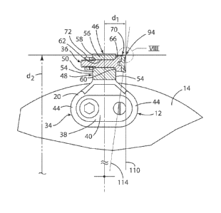
longitudinal distance d1, i.e., the distance between the pocket radial 116 and
cutting edge 94 of the cutting tip 70, coupled with the distance d7, the
distance from the
rotational axis 22 to the cutting edge 94 of the cutting tip 70, combine to
locate the cutting
edge 94 of the cutting tip 70. It should be understood that varying either one
of these
parameters will change the effective angle between the outer, intermediate,
and inner surfaces
104, 106. 108 of the cutting tip 70 and the workpiece or stump. It may be
necessary to start
with a cutting tip 70 having different angles then those set forth in the
embodiment above,
which is only an example of one set of surface angles that can be used with a
cutting bit 70.
[0063] The description of the invention is merely exemplary in nature and,
thus, variations
that do not depart from the gist of the invention are intended to be within
the scope of the
invention. Such variations are not to be regarded as a departure from the
spirit and scope of
the invention.
16