Note: Descriptions are shown in the official language in which they were submitted.
CA 02931884 2016-06-13
52663-209
METHOD FOR REDUCING SELF-INTERFERENCE SIGNAL IN
COMMUNICATIONS SYSTEM, AND APPARATUS
TECHNICAL FIELD
[0001] Embodiments of the present invention relate to the field of
communications technologies,
and in particular, to a method for reducing a self-interference signal in a
communications system,
and an apparatus.
BACKGROUND
[0002] In a wireless communications system such as a mobile cellular
communications system,
a wireless local area network (Wireless Local Area Network, WEAN), and fixed
wireless access
(Fixed Wireless Access, FWA), a communications node such as a base station
(Base Station, BS),
an access point (Access Point, AP), a relay station (Relay Station, RS), or
user equipment (User
Equipment, UE) usually has a capabilities of sending a signal of the
communications node and
receiving a signal from another communications node. Because a wireless signal
is greatly
attenuated on a wireless channel, and compared with a signal sent by the
communications node,
when a signal from a communications transmit end is very weak when arriving at
a receive end. For
example, a difference between a power for receiving a signal and a power for
sending a signal by a
communications node in a mobile cellular communications system can reach 80 dB
to 120 dB or
can be even larger. Therefore, to avoid interference (such interference is
referred to as
self-interference, Self-interference) to a received signal of a communications
node from a sending
signal of the communications node, transmission and reception of a wireless
signal are
distinguished by using different frequency bands or time periods. For example,
in frequency
division duplex (Frequency Division Duplex, FDD), communication in
transmission and reception
are performed by using different frequency bands separated by a certain guard
band. In time
division duplex (Time Division Duplex, TDD), communication in transmission and
reception are
performed by using different time periods separated by a guard interval. The
guard band in the FDD
system and the guard interval in the TDD system are both for the purpose of
ensuring that reception
and transmission are thoroughly separated, thereby avoiding interference to
reception from
transmission.
[0003] In the wireless full duplex technology, reception and transmission
operations can be
CA 02931884 2016-05-27
simultaneously performed on a same wire,less channel. Theoretically, the
spectral efficiency of the
wireless full duplex technology is twice as high as that of the FDD technology
or the TDD
technology. However, because there is no guard band or guard interval, a
transmitted signal of a
communications node that supports wireless full duplex may result in
interference to a received
signal of the communications node, causing that the communications node cannot
correctly receive
a wanted signal. Self-interference includes a near-field reflected self-
interference signal on a
near-field reflection channel and a far-field reflected self-interference
signal on a far-field reflection
channel. The near-field reflected self-interference signal typically
corresponds to a near-field
reflection path of 0.3 m to 60 m, and a multi-path transmission delay is 1 ns
to 400 ns. Because
propagation environments around a transceving antenna change slightly, a delay
of a component of
the near-field reflected self-interference signal changes slightly and slowly
with time. The near-field
reflected self-interference signal is a self-interference component that is
the most difficult to
effectively cancel in a wireless full duplex system, and reasons are as
follows: Because a
propagation distance of a near-field multi-path echo signal is relatively
short, a propagation delay
difference between multiple paths is very small, when a communication signal
of a normal
bandwidth (10 MHz to 40 MHz) is used, the near-field reflected self-
interference signal cannot be
effectively recognized and reconstructed, and effective interference
cancellation cannot be
implemented. For example, a difference between delays of two reflectors whose
straight-line
propagation distances from the communications node have a difference of 3
meters is 20 ns, and
distinguishing is very difficult. Due to a relatively large multi-path delay
difference, a component of
a far-end reflected self-interference signal can be recognized when a signal
having a normal
bandwidth is used, thereby implementing effective cancellation. Therefore, how
to determine a
near-field reflection channel parameter that can be used to reconstruct a near-
field reflected
self-interference signal is a key issue for cancelling the near-field
reflected self-interference signal.
SUMMARY
[0004] The present invention provides a method for reducing a self-
interference signal in a
communications system, and an apparatus, which can determine a near-field
reflection channel
parameter used to estimate a near-field reflected self-interference signal,
and reduce near-field
self-interference signals in received signals by using the near-field
reflection channel parameter.
[0005] According to a first aspect, an embodiment of the present invention
provides an
apparatus, where the apparatus includes: a sending unit, configured to send a
sounding signal and a
first communication signal, where the sounding signal is sent in a manner of
being superimposed on
the first communication signal, and a power used to send the sounding signal
is less than a power
2
CA 02931884 2016-05-27
used to send the first communication signg a receiving unit, configured to
receive an input signal,
where the input signal includes an echo signal and a second communication
signal sent by another
apparatus, and the echo signal includes a near-field reflected signal
corresponding to the sounding
signal; a signal separation unit, configured to separate the near-field
reflected signal from the echo
signal; a processing unit for a near-field reflected self-interference signal,
configured to determine a
near-field reflection channel parameter according to the near-field reflected
signal; and a
cancellation unit for a near-field reflected self-interference signal,
configured to determine a
reconstructed near-field reflected self-interference signal based on the near-
field reflection channel
parameter, and subtract the reconstructed near-field reflected self-
interference signal from the
second communication signal.
[0006] With reference to the first aspect, in a first possible
implementation manner, the sending
unit is specifically configured to send the sounding signal in a transmit
timeslot in a sounding
timeslot, and stop sending the sounding signal in an idle timeslot in the
sounding timeslot, where
the idle timeslot includes a first silent timeslot and a second silent
timeslot.
[0007] With reference to the first aspect or the first possible
implementation manner, in a
second possible implementation manner, the sending unit is specifically
configured to send the
sounding signal by using a bandwidth that is greater than or equal to a
bandwidth used to send the
first communication signal.
[0008] With reference to the second possible implementation manner, in a
third possible
implementation manner, when the sending unit sends the sounding signal by
using a bandwidth that
is greater than the bandwidth used to send the first communication signal, the
processing unit for a
near-field reflected self-interference signal is specifically configured to
perform matched filtering
on the near-field reflected signal, to obtain a filtered near-field reflected
signal, and determine the
near-field reflection channel parameter according to the filtered near-field
reflected signal.
[0009] With reference to the second possible implementation manner, in a
fourth possible
implementation manner, when the sending unit sends the sounding signal by
using a bandwidth that
is greater than the bandwidth used to send the first communication signal, the
processing unit for a
near-field reflected self-interference signal is specifically configured to
perform matched filtering
on multiple near-field reflected signals, to obtain multiple filtered near-
field reflected signals,
determine an average value of the multiple filtered near-field reflected
signals, and determine the
near-field reflection channel parameter according to the average value of the
multiple filtered
near-field reflected signals; or the processing unit for a near-field
reflected self-interference signal is
specifically configured to determine an average near-field reflected signal
corresponding to multiple
near-field reflected signals, perform matched filtering on the average near-
field reflected signal, to
3
CA 02931884 2016-05-27
obtain a filtered average near-field reflected signal, and determine the near-
field reflection channel
parameter according to the filtered average near-field reflected signal.
[0010] With reference to the second possible implementation manner, in a
fifth possible
implementation manner, when the sending unit sends the sounding signal by
using a bandwidth that
is equal to the bandwidth used to send the first communication signal, the
processing unit for a
near-field reflected self-interference signal is specifically configured to
determine the near-field
reflection channel parameter by using a super-resolution delay algorithm.
[0011] With reference to the first aspect or any one of the foregoing
possible implementation
manners, in a sixth possible implementation manner, when the apparatus
supports multiple-input
multiple-output MLMO, the sending unit is specifically configured to
separately send the sounding
signal by using multiple antennas of the apparatus, where timeslots in which
the multiple antennas
separately send the sounding signal are mutually staggered.
[0012] With reference to the first aspect or any one of the foregoing
possible implementation
manners, in a seventh possible implementation manner, the sending unit is
specifically configured
to send the sounding signal by using a timeslot that is staggered with a
timeslot used for sending a
sounding signal by an adjacent apparatus supporting wireless full duplex.
[0013] With reference to the first aspect or any one of the first
possible implementation manner
to the fifth possible implementation manner, in an eighth possible
implementation manner, the
sending unit is specifically configured to send the sounding signal by using M
random sounding
timeslots, where M is an average quantity of near-field reflected signals that
correspond to the
sounding signal and are accumulated by the apparatus supporting wireless full
duplex within a
coherent accumulation time for receiving the echo signal.
[0014] According to a second aspect, an embodiment of the present
invention provides an
apparatus, where the apparatus includes: a transmit antenna, configured to
send a sounding signal
and a first communication signal, where the sounding signal is sent in a
manner of being
superimposed on the first communication signal, and a power used to send the
sounding signal is
less than a power used to send the first communication signal; a receive
antenna, configured to
receive an echo signal, where the echo signal includes a near-field reflected
signal corresponding to
the sounding signal; a signal separator, configured to separate the near-field
reflected signal from
the echo signal; a processor for a near-field reflected self-interference
signal, configured to
determine a near-field reflection channel parameter according to the near-
field reflected signal; and
a canceller for a near-field reflected self-interference signal, configured to
determine a reconstructed
near-field reflected self-interference signal based on the near-field
reflection channel parameter, and
subtract the reconstructed near-field reflected self-interference signal from
a second communication
4
CA 02931884 2016-05-27
=
signal.
[0015] With reference to the second aspect, in a first possible
implementation manner, the
transmit antenna is specifically configured to send the sounding signal in a
transmit timeslot in a
sounding timeslot, and stop sending the sounding signal in an idle timeslot in
the sounding timeslot,
where the idle timeslot includes a first silent timeslot and a second silent
timeslot.
[0016] With reference to the second aspect or the first possible
implementation manner, in a
second possible implementation manner, the transmit antenna is specifically
configured to send the
sounding signal by using a bandwidth that is greater than or equal to a
bandwidth used to send the
first communication signal.
[0017] With reference to the second possible implementation manner, in a
third possible
implementation manner, when the transmit antenna sends the sounding signal by
using a bandwidth
that is greater than the bandwidth used to send the first communication
signal, the processor for a
near-field reflected self-interference signal is specifically configured to
perform matched filtering
on the near-field reflected signal, to obtain a filtered near-field reflected
signal, and determine the
near-field reflection channel parameter according to the filtered near-field
reflected signal.
[0018] With reference to the second possible implementation manner, in a
fourth possible
implementation manner, when the transmit antenna sends the sounding signal by
using a bandwidth
that is greater than the bandwidth used to send the first communication
signal, the processor for a
near-field reflected self-interference signal is specifically configured to
perform matched filtering
on multiple near-field reflected signals, to obtain multiple filtered near-
field reflected signals,
determine an average value of the multiple filtered near-field reflected
signals, and determine the
near-field reflection channel parameter according to the average value of the
multiple filtered
near-field reflected signals; or the processor for a near-field reflected self-
interference signal is
specifically configured to determine an average near-field reflected signal
corresponding to multiple
near-field reflected signals, perform matched filtering on the average near-
field reflected signal, to
obtain a filtered average near-field reflected signal, and determine the near-
field reflection channel
parameter according to the filtered average near-field reflected signal.
[0019] With reference to the second possible implementation manner, in a
fifth possible
implementation manner, when the transmit antenna sends the sounding signal by
using a bandwidth
that is equal to the bandwidth used to send the first communication signal,
the processor for a
near-field reflected self-interference signal is specifically configured to
determine the near-field
reflection channel parameter by using a super-resolution delay algorithm.
[0020] With reference to the second aspect or any one of the foregoing
possible implementation
manners, in a sixth possible implementation manner, when the apparatus
supports multiple-input
5
CA 02931884 2016-05-27
=
multiple-output MIMO, the transmit antenna is specifically configured to
separately send the
sounding signal by using multiple antennas of the apparatus, where timeslots
in which the multiple
antennas separately send the sounding signal are mutually staggered.
[0021] With reference to the second aspect or any one of the foregoing
possible implementation
manners, in a seventh possible implementation manner, the transmit antenna is
specifically
configured to send the sounding signal by using a timeslot that is staggered
with a timeslot used for
sending a sounding signal by an adjacent apparatus supporting wireless full
duplex.
[0022] With reference to the second aspect or any one of the first
possible implementation
manner to the fifth possible implementation manner, in an eighth possible
implementation manner,
the transmit antenna is specifically configured to send the sounding signal by
using M random
sounding timeslots, where M is an average quantity of near-field reflected
signals that correspond to
the sounding signal and are accumulated by the apparatus supporting wireless
full duplex within a
coherent accumulation time for receiving the echo signal.
[0023] According to a third aspect, an embodiment of the present
invention provides a method
for reducing a self-interference signal in a communications system, where the
method is performed
by an apparatus supporting wireless full duplex, and the method includes:
sending a sounding signal
and a first communication signal, where the sounding signal is sent in a
manner of being
superimposed on the first communication signal, and a power used to send the
sounding signal is
less than a power used to send the first communication signal; receiving an
input signal, where the
input signal includes an echo signal and a second communication signal that is
received from
another apparatus, and the echo signal includes a near-field reflected signal
corresponding to the
sounding signal; separating the near-field reflected signal from the echo
signal; determining a
near-field reflection channel parameter according to the near-field reflected
signal; and determining
a reconstructed near-field reflected self-interference signal based on the
near-field reflection
channel parameter, and subtracting the reconstructed near-field reflected self-
interference signal
from the second communication signal.
100241 With reference to the third aspect, in a first possible
implementation manner, the sending
a sounding signal includes: transmitting the sounding signal in a transmit
timeslot in a sounding
timeslot; and the method further includes: stopping transmitting the sounding
signal in an idle
timeslot in the sounding timeslot, where the idle timeslot includes a first
silent timeslot and a
second silent timeslot.
[0025] With reference to the first possible implementation manner, in a
second possible
implementation manner, duration of the first silent timeslot is equal to a
maximum multi-path delay
of a near-field reflection channel, a value of the second silent timeslot
enables a delay of an echo
6
CA 02931884 2016-05-27
multi-path component to exceed a ,sum of the duration of the first silent
timeslot and duration of the
second silent timeslot, and a power of the echo multi-path component is less
than a preset threshold.
[0026] With reference to the first aspect or any one of the foregoing
possible implementation
manners, in a third possible implementation manner, the sending a sounding
signal and a first
communication signal includes: sending the sounding signal by using a
bandwidth that is greater
than or equal to a bandwidth used to send the first communication signal.
[0027] With reference to the third possible implementation manner, in a
fourth possible
implementation manner, when a bandwidth used to send the sounding signal is
greater than the
bandwidth used to send the first communication signal, the determining a near-
field reflection
channel parameter according to the near-field reflected signal includes:
performing matched
filtering on the near-field reflected signal, to obtain a filtered near-field
reflected signal, and
determining the near-field reflection channel parameter according to the
filtered near-field reflected
signal.
[0028] With reference to the third possible implementation manner, in a
fifth possible
implementation manner, when a bandwidth used to send the sounding signal is
greater than the
bandwidth used to send the first communication signal, the determining a near-
field reflection
channel parameter according to the near-field reflected signal includes:
performing matched
filtering on multiple near-field reflected signals, to obtain multiple
filtered near-field reflected
signals, determining an average value of the multiple filtered near-field
reflected signals, and
determining the near-field reflection channel parameter according to the
average value of the
multiple filtered near-field reflected signals; or determining an average near-
field reflected signal
corresponding to multiple near-field reflected signals, performing matched
filtering on the average
near-field reflected signal, to obtain a filtered average near-field reflected
signal, and determining
the near-field reflection channel parameter according to the filtered average
near-field reflected
signal.
[0029] With reference to the third possible implementation manner, in a
sixth possible
implementation manner, when a bandwidth used to send the sounding signal is
equal to the
bandwidth used to send the first communication signal, the determining a near-
field reflection
channel parameter according to the near-field reflected signal includes:
determining the near-field
reflection channel parameter by using a super-resolution delay algorithm.
[0030] With reference to the third aspect or any one of the foregoing
possible implementation
manners, in a seventh possible implementation manner, when the apparatus
supports multiple-input
multiple-output MIMO, the sending a sounding signal includes: separately
sending the sounding
signal by using multiple antennas of the apparatus, where timeslots in which
the multiple antennas
7
= 81797269
separately send the sounding signal are mutually staggered.
[0031] With reference to third aspect or any one of the foregoing
possible implementation
manners, in an eighth possible implementation manner, the sending a sounding
signal includes:
sending the sounding signal by using a timeslot that is staggered with a
timeslot used for sending a
sounding signal by an adjacent apparatus supporting wireless full duplex.
[0032] With reference to the third aspect or any one of the first
possible implementation manner
to the sixth possible implementation manner, in a ninth possible
implementation manner, the sending a
sounding signal and a first communication signal includes: sending the
sounding signal by using M
random sounding timeslots, where M is an average quantity of near-field
reflected signals that
correspond to the sounding signal and are accumulated by the apparatus
supporting wireless full
duplex within a coherent accumulation time for receiving the echo signal.
[0032a] Another aspect of the present disclosure provides an apparatus,
wherein the apparatus
comprises: a sending unit, configured to send a sounding signal and a first
communication signal,
wherein the sounding signal is sent in a manner of being superimposed on the
first communication
signal, and a power used to send the sounding signal is less than a power used
to send the first
communication signal; wherein the sending unit is specifically configured to
send the sounding signal
by using a bandwidth that is greater than a bandwidth used to send the first
communication signal; a
receiving unit, configured to receive an input signal, wherein the input
signal comprises an echo signal
and a second communication signal sent by another apparatus, and the echo
signal comprises a
near-field reflected signal corresponding to the sounding signal; a signal
separation unit, configured to
separate the near-field reflected signal from the echo signal; a processing
unit for a near-field reflected
self-interference signal, configured to determine a near-field reflection
channel parameter according to
the near-field reflected signal; and a cancellation unit for a near-field
reflected self-interference signal,
configured to determine a reconstructed near-field reflected self-interference
signal based on the
near-field reflection channel parameter, and subtract the reconstructed near-
field reflected
self-interference signal from the second communication signal.
10032b1 Another aspect of the present disclosure provides an apparatus,
wherein the apparatus
comprises: a transmit antenna, configured to send a sounding signal and a
first communication signal,
wherein the sounding signal is sent in a manner of being superimposed on the
first communication
signal, and a power used to send the sounding signal is less than a power used
to send the first
communication signal; wherein the transmit antenna is specifically configured
to send the sounding
signal by using a bandwidth that is greater than a bandwidth used to send the
first communication
signal; a receive antenna, configured to receive an echo signal, wherein the
echo signal comprises a
8
CA 2931884 2017-09-21
81797269
near-field reflected signal corresponding to the sounding signal; a signal
separator, configured to
separate the near-field reflected signal from the echo signal; a processor for
a near-field reflected
self-interference signal, configured to determine a near-field reflection
channel parameter according to
the near-field reflected signal; and a canceller for a near-field reflected
self-interference signal,
configured to determine a reconstructed near-field reflected self-interference
signal based on the
near-field reflection channel parameter, and subtract the reconstructed near-
field reflected
self-interference signal from a second communication signal.
[0032c] Another aspect of the present disclosure provides a method for
reducing a
self-interference signal in a communications system, wherein the method is
performed by an apparatus
supporting wireless full duplex, and the method comprises: sending a sounding
signal and a first
communication signal, wherein the sounding signal is sent in a manner of being
superimposed on the
first communication signal, and a power used to send the sounding signal is
less than a power used to
send the first communication signal; wherein the sending a sounding signal and
a first communication
signal comprises: sending the sounding signal by using a bandwidth that is
greater than or equal to a
bandwidth used to send the first communication signal; receiving an input
signal, wherein the input
signal comprises an echo signal and a second communication signal received
from another apparatus,
and the echo signal comprises a near-field reflected signal corresponding to
the sounding signal;
separating the near-field reflected signal from the echo signal; determining a
near-field reflection
channel parameter according to the near-field reflected signal; and
determining a reconstructed
near-field reflected self-interference signal based on the near-field
reflection channel parameter, and
subtracting the reconstructed near-field reflected self-interference signal
from the second
communication signal.
[0033] According to the present invention, an apparatus supporting
wireless full duplex can
transmit a sounding signal, determine, by separating a near-field reflected
signal corresponding to the
sounding signal, a near-field reflection channel parameter corresponding to
the near-field reflected
signal, determine a reconstructed near-field reflected self-interference
signal by using the near-field
reflection channel parameter, and subtract the reconstructed near-field
reflected self-interference signal
from a near-field reflected self-interference signal in a received second
communication signal. This
can effectively reduce a near-field reflected self-interference signal in
received signals.
BRIEF DESCRIPTION OF DRAWINGS
[0034] To describe the technical solutions in the embodiments of the
present invention more
clearly, the following briefly introduces the accompanying drawings required
for describing the
embodiments of the present invention. Apparently, the accompanying drawings in
the following
8a
CA 2931884 2017-09-21
= 81797269
description show merely some embodiments of the present invention, and a
person of ordinary skill in
the art may still derive other drawings from these accompanying drawings
without creative efforts.
[0035] FIG. 1 is a schematic flowchart of a method for reducing a self-
interference signal in a
communications system according to an embodiment of the present invention;
[0036] FIG. 2 is a schematic flowchart of a method for reducing a self-
interference signal in a
communications system according to an embodiment of the present invention;
[0037] FIG. 3 is a schematic diagram of a timeslot structure according to
an embodiment of the
present invention;
100381 FIG. 4 is a schematic diagram of another timeslot structure
according to an embodiment
8b
CA 2931884 2017-09-21
CA 02931884 2016-05-27
=
of the present invention;
[0039] FIG. 5 is a schematic diagram of another timeslot structure
according to an embodiment
of the present invention;
[0040] FIG. 6 is a structural block diagram of an apparatus according to
an embodiment of the
present invention; and
[0041] FIG. 7 is a structural block diagram of an apparatus according to
an embodiment of the
present invention.
DESCRIPTION OF EMBODIMENTS
[0042] The following clearly and completely describes the technical
solutions in the
embodiments of the present invention with reference to the accompanying
drawings in the
embodiments of the present invention. Apparently, the described embodiments
are merely some but
not all of the embodiments of the present invention. All other embodiments
obtained by a person of
ordinary skill in the art based on the embodiments of the present invention
without creative efforts
shall fall within the protection scope of the present invention.
[0043] It should be understood that, technical solutions in the embodiments
of the present
invention may be applied to a wireless full duplex system. A communications
node such as user
equipment and a base station provided in the embodiments of the present
invention supports the
wireless full duplex system.
[0044] User equipment (User Equipment, UE), may also be referred to as a
mobile terminal
(Mobile Terminal, MT), mobile user equipment, and the like, may communicate
with one or more
core networks by using a radio access network (Radio Access Network, RAN). The
user equipment
may be a mobile terminal, such as a mobile phone (which is also referred to as
a "cellular" phone)
and a computer with a mobile terminal. For example, the user equipment may be
a portable,
pocket-sized, handheld, computer built-in, or in-vehicle mobile apparatus.
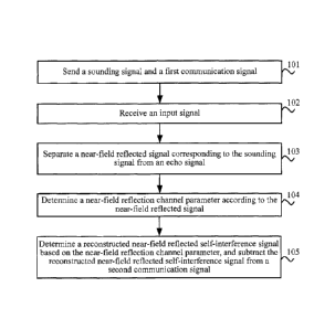
[0045] FIG. 1 is a schematic flowchart of a method for reducing a self-
interference signal in a
communications system according to an embodiment of the present invention. The
method shown
in FIG. 1 is performed by an apparatus supporting wireless full duplex, and
the apparatus may be
located in a communications node such as user equipment and a base station.
[0046] 101: Send a sounding signal and a first communication signal,
where the sounding signal
is sent in a manner of being superimposed on the first communication signal,
and a power used to
send the sounding signal is less than a power used to send the first
communication signal.
[0047] 102: Receive an input signal, where the input signal includes a
second communication
signal and an echo signal, the echo signal includes a near-field reflected
signal corresponding to the
9
CA 02931884 2016-05-27
sounding signal, and the second communigation signal is sent by another
apparatus.
[0048] 103: Separate the near-field reflected signal corresponding to the
sounding signal from
the echo signal.
[0049] 104: Determine a near-field reflection channel parameter according
to the near-field
reflected signal.
[0050] 105: Determine a reconstructed near-field reflected self-
interference signal based on the
near-field reflection channel parameter, and subtract the reconstructed near-
field reflected
self-interference signal from the second communication signal.
[0051] According to the method shown in FIG. 1, a near-field reflection
channel parameter used
to reconstruct a near-field self-interference signal can be determined, a
reconstructed near-field
reflected self-interference signal is determined by using the near-field
reflection channel parameter,
and the reconstructed near-field reflected self-interference signal is
subtracted from a near-field
reflected self-interference signal in a received second communication signal.
According to the
method shown in FIG. 1, a near-field reflected signal can be effectively
recognized and
reconstructed, and near-field reflected self-interference signals in received
signals can be reduced.
[0052] FIG. 2 is a schematic flowchart of a method for reducing a self-
interference signal in a
communications system according to an embodiment of the present invention. The
embodiment in
FIG. 2 is a specific embodiment of the method shown in FIG. 1.
[0053] 201: Send a sounding signal and a first communication signal,
where the sounding signal
is sent in a manner of being superimposed on the first communication signal.
[0054] Specifically, a communications node (first communications node for
short below) that
includes an apparatus supporting wireless full duplex communicates with
another communications
node. A signal that is generated by the first communications node and used for
communicating with
another communications node is referred to as a first communication signal,
and the first
communication signal includes all information, such as data information and
control information,
used for communicating with another communications node. In addition to
generating the first
communication signal, the first communications node further generates a
sounding signal, and the
sounding signal is used for measuring a near-field reflection channel
parameter.
[0055] The apparatus sends the sounding signal in a transmit timeslot in
a sounding timeslot 1,
and stops sending the sounding signal in an idle timeslot in the sounding
timeslot, where the idle
timeslot includes a first silent timeslot 61 and a second silent timeslot 62 .
Specifically, a
sounding signal with a bandwidth of B and a time length of T is sent in the
transmit timeslot in 1,
and the sounding signal is a large time-bandwidth product signal, where TB >>
1. A typical large
CA 02931884 2016-05-27
=
time-bandwidth product ("time-bandwidth, product" for short) signal used for
the sounding signal
may be linear frequency modulation signal, non-linear frequency modulation
signal, or the like.
Usually, to reduce out-of-band emission, the sounding signal may also be a
large time-bandwidth
product signal that is obtained after windowing, where a typical window
function used for
windowing may be a Hamming (Hamming) window, a Banning (Harming) window, a
Tayler
(Tayler) window, or the like. Then, the apparatus remains silent in the idle
timeslot, and does not
send any signal in this period, so that the apparatus can perform echo
detection. Optionally, duration
of the first silent timeslot bi in the idle timeslot may be equal to a maximum
multi-path delay of a
near-field reflection channel, a value of the second silent timeslot 82 in the
idle timeslot enables a
delay of an echo multi-path component to exceed a sum of the duration of the
first silent timeslot
and duration of the second silent timeslot, and a power of the echo multi-path
component is less
than a preset threshold. Therefore, the sounding signal does not cause
interference to detection on a
sounding signal in a next sounding timeslot, where typically 82 = 381 ¨ 481 .
Because the
sounding signal is sent in a manner of being superimposed on the first
communication signal,
stopping sending the sounding signal in the idle timeslot by a transmitter of
the apparatus does not
affect sending the first communication signal by the transmitter of the
apparatus. In addition, the
sounding signal is only used to estimate a near-field reflection channel, and
therefore 81 << T.
Further, a power used to send the sounding signal is less than a power used to
send the first
communication signal. Typically, when a transmit power of the sounding signal
is less than a
transmit power of the first communication signal by more than 20 dB,
interference from the
sounding signal to transmission of a communications opposite end may be
ignored.
[0056] Optionally, in an embodiment, the apparatus may send the sounding
signal by using a
timeslot structure shown in FIG. 3, that is, the sounding timeslot is
continuously sent.
[0057] Optionally, in another embodiment, the apparatus may send the
sounding signal by using
a timeslot structure shown in FIG. 4, that is, send the sounding signal in a
transmit timeslot in N
consecutive sounding timeslots, and the transmitter of the apparatus stops
sending the sounding
signal in a stop timeslot, and then, sends the sounding signal again in N
consecutive sounding
timeslots, where N is a positive integer greater than or equal to 2. Because
the sounding signal is
superimposed on the first communication signal, stopping sending the sounding
signal does not
affect sending the first communication signal by the transmitter of the
apparatus. When the timeslot
structure shown in FIG. 3 or FIG. 4 is used, it may be that
2 = 381 ¨ 461, for example, 82 =1.6
,us
[0058] Optionally, in another embodiment, the apparatus may send the
sounding signal by using
11
CA 02931884 2016-05-27
a timeslot structure shown in FIG. ,5, that s, send a sounding signal in a
sounding timeslot, and the
transmitter of the apparatus stops sending the sounding signal in a stop
timeslot, and then, sends the
sounding signal again in a sounding timeslot. When the sounding signal is sent
by using the timeslot
structure shown in FIG. 5, if a time of the stop timeslot is long, a value of
82 may be 0. For
example, when a near-field reflection channel within a radius of 60 m of the
apparatus is considered,
it may be that 1=400 ns, and 82 =0 ns. A stop timeslot for stopping sending
the sounding signal
is added to a timeslot shown in FIG. 5, so that a timeslot for stopping
sending the sounding signal is
prolonged. In this way, efficiency of detecting a near-field reflection
channel can be improved, and
interference to a communication signal can be reduced as much as possible.
[0059] Optionally, in an embodiment, a bandwidth used to send the sounding
signal by the
apparatus may be equal to a bandwidth used to send the first communication
signal. For example, a
bandwidth of a communication channel on which the first communication signal
is located is 20
MHz, and the first communication signal is in 2.44 GHz to 2.46 GHz, and has a
central frequency
of 2.45 GHz; the sounding signal is located in a same frequency band, uses a
linear frequency
modulation signal having a large time-bandwidth product TB=80, where a
bandwidth B=20 MHz,
and T=4 1/S In In this case, if the timeslot structure shown in FIG. 3 or FIG.
4 is used, the sounding
timeslot I may be equal to 6 ps
[0060] Optionally, in another embodiment, a bandwidth used to send the
sounding signal by the
apparatus may be greater than the bandwidth used to send the first
communication signal. For
example, a bandwidth of a communication channel on which the first
communication signal is
located is 20 MHz, and a bandwidth B of the sounding signal is 80 MHz. In this
way, the apparatus
may recognize a multi-path delay of 12 ns. hi this case, even though the
bandwidth of the sounding
signal is greater than the bandwidth of the first communication signal, the
sounding signal and the
first communication signal are in a same frequency band, it may still be
ensured that a wireless
channel parameter measured by using the sounding signal is approximately the
same as a channel
parameter of the communication channel on which the first communication signal
is located. For
another example, a bandwidth of the first communication signal is 20 MHz, and
the first
communication signal is in 2.44 GHz to 2.46 GHz, and has a central frequency
of 2.45 GHz; the
sounding signal uses a non-linear frequency modulation signal in a Hanning
window and having a
time-bandwidth product TB of 160. In this case, if the timeslot structure
shown in FIG. 3 or FIG. 4
is used, the sounding timeslot may be equal to 4 ps
[0061] Optionally, in an embodiment, when the apparatus supports multiple-
input
multiple-output (Multiple-Input Multiple-Output, MIMO), the apparatus
separately sends the
12
CA 02931884 2016-05-27
sounding signal by using multiple, antennas, and separately receives an input
signal by using the
multiple antennas, where transmit timeslots in which the multiple antennas
transmit the sounding
signal are mutually staggered. That is, at any moment, only one branch
transmits the sounding
signal and receives an echo signal of the sounding signal. In this way,
branches do not interfere with
each other. Therefore, all antennas can share one sounding signal. hi this
case, if sounding timeslots
0
of near-field reflection channels of branches are separated by 63, where 3
, a value of a
second silent timeslot 2 in a sounding timeslot of a near-field reflection
channel of each branch
enables a power of an echo multi-path component of a sounding signal whose
delay exceeds
81 + 82 +83 to be low enough, so that the sounding signal does not interfere
with detection on a
near-field reflected echo signal in a sounding timeslot of a near-field
reflection channel of another
subsequent branch.
100621
Optionally, in an embodiment, for an adjacent apparatus supporting wireless
full duplex,
a transmit timeslot in which the apparatus sends the sounding signal and a
transmit timeslot in
which an adjacent (for example, at a distance of several meters to tens of
meters) apparatus
supporting wireless full duplex sends the sounding signal are mutually
staggered. In other words,
sounding timeslots of near-field reflection channels of a communications node
A and a
communications node B that are adjacent to each other are mutually staggered,
and when either
node transmits a sounding signal and receives an echo signal, a transmitter of
the other
communications node does not transmit the sounding signal. If sounding
timeslots of near-field
reflection channels of branches are separated by 83 , where 83 0, a value of a
second silent
timeslot 82 in a sounding timeslot of a near-field reflection channel of each
node enables a power
of an echo multi-path component of a sounding signal whose delay exceeds 81 +
(52 + 83 to be
low enough, so that the sounding signal causes no interference to detection on
a near-field reflected
echo signal in a sounding timeslot of a near-field reflection channel of
another subsequent node.
100631 Optionally, in another embodiment, it is assumed that there are k
communications nodes
that are separated by a short distance, and a sounding signal between the k
communications nodes
may be interfered with. An average quantity of near-field reflected signals
that correspond to the
sounding signal and are accumulated by each communications node in the k
communications nodes
within a coherent accumulation time 7? for detecting the echo signal is m, and
each
communications node in the k communications nodes can randomly allocate m
sounding timeslots
in Ty, mkT
1 . In this way, for each communications node in the k communications nodes,
near-field reflected signals in m sounding timeslots of each communications
node are coherently
13
CA 02931884 2016-05-27
=
accumulated, and a sounding timeslot of another communications node appears
randomly. Because
in multiple random signals, some are positive, and some are negative, the
multiple random signals
may cancel each other in an accumulation process, which therefore effectively
lowers mutual
interference of sounding signals between communications nodes that are
separated by a short
distance. In this embodiment, arc coordination between communications nodes or
centralized
allocation by a system is not needed, which lowers complexity of the system.
[0064] 202: Receive an input signal, where the input signal includes a
second communication
signal and an echo signal, the echo signal includes a near-field reflected
signal corresponding to the
sounding signal and a data reflected signal corresponding to the first
communication signal, and the
second communication signal is a communication signal sent by another
apparatus to a first
communications node.
[0065] 203: Separate the near-field reflected signal corresponding to the
sounding signal from
the echo signal.
[0066] Specifically, the near-field reflected signal is distinguished
based on time according to a
timeslot structure of the sounding signal.
[0067] 204: Determine a near-field reflection channel parameter according
to the near-field
reflected signal.
[0068] Optionally, in an embodiment, when a bandwidth used to send the
sounding signal by
the apparatus is greater than the bandwidth used to send the first
communication signal, the
near-field reflection channel parameter may be calculated by using matched
filtering.
[0069] Optionally, in another embodiment, the apparatus may further
determine the near-field
reflection channel parameter by using a coherent accumulation method.
Specifically, the apparatus
may perform matched filtering on multiple near-field reflected signals, to
obtain multiple filtered
near-field reflected signals, determine an average value of the multiple
filtered near-field reflected
signals, and determine the near-field reflection channel parameter according
to the average value of
the multiple filtered near-field reflected signals. Alternatively, the
apparatus may determine an
average near-field reflected signal corresponding to multiple near-field
reflected signals (that is,
obtain an average value of the multiple near-field reflected signals), perform
matched filtering on
the average near-field reflected signal, to obtain a filtered average near-
field reflected signal, and
determine the near-field reflection channel parameter according to the
filtered average near-field
reflected signal.
[0070] Optionally, in another embodiment, when a bandwidth used to send
the sounding signal
by the apparatus is equal to the bandwidth used to send the first
communication signal, the
near-field reflected signal may be sampled, and the near-field reflection
channel parameter is
14
CA 02931884 2016-05-27
determined by using a super-resolution delay algorithm according to a sampling
result, where a
typical super-resolution delay algorithm includes: maximum likelihood
estimation, high-resolution
direction-of-arrival estimation algorithm based on array signal processing,
matching pursuit,
orthogonal matching pursuit, and the like.
[0071] 205: Determine a reconstructed near-field reflected self-
interference signal based on the
near-field reflection channel parameter.
[0072]
Specifically, the reconstructed near-field reflected self-interference signal
may be
determined by using the following formula:
y(t) x(t)* h(t), .................................... 1.1
where, y(t) represents a reconstructed near-field reflected self-interference
signal, x(t)
represents a reconstructed reference signal, h(t) represents a near-field
reflection channel parameter,
a symbol "* "represents a convolution, and the reconstructed reference signal
is known. Therefore,
when the near-field reflection channel parameter is determined, the
reconstructed near-field
reflected self-interference signal may be determined by using the formula 1.1.
[0073] 206: Subtract the reconstructed near-field reflected self-
interference signal from the
received second communication signal, where the second communication signal is
sent by another
apparatus.
[0074]
According to the method shown in FIG. 2, a near-field reflection channel
parameter used
to reconstruct a near-field self-interference signal can be determined, a
reconstructed near-field
reflected self-interference signal is determined by using the near-field
reflection channel parameter,
and the reconstructed near-field reflected self-interference signal is
subtracted from a near-field
reflected self-interference signal of a received second communication signal.
According to the
method shown in FIG. 1, a near-field reflected signal can be effectively
recognized and
reconstructed, and near-field reflected self-interference signals in received
signals can be reduced.
[0075] FIG. 3 is a schematic diagram of a timeslot structure according to
an embodiment of the
present invention. As shown in FIG. 3, a sounding signal is superimposed on a
first communication
signal, and sounding timeslots are consecutive.
[0076]
FIG. 4 is a schematic diagram of another timeslot structure according to an
embodiment
of the present invention. As shown in FIG. 4, a sounding signal is
superimposed on a first
communication signal. and N sounding timeslots and one stop timeslot appear
alternately, where N
is a positive integer greater than or equal to 2.
[0077]
FIG. 5 is a schematic diagram of another timeslot structure according to an
embodiment
of the present invention. As shown in FIG. 5, a sounding signal is sent in a
manner of being
superimposed on a first communication signal, and a sounding timeslot and a
stop timeslot appear
CA 02931884 2016-05-27
=
alternately.
[0078] FIG. 6 is a structural block diagram of an apparatus according to
an embodiment of the
present invention. An apparatus 600 shown in FIG. 6 is an apparatus supporting
wireless full duplex,
and can perform steps in FIG. 1 or FIG. 2. As described in FIG. 6, the
apparatus 600 includes: a
sending unit 601, a receiving unit 602, a signal separation unit 603, and a
processing unit 604 for a
near-field reflected self-interference signal.
[0079] The sending unit 601 is configured to send a sounding signal and a
first communication
signal, where the sounding signal is sent in a manner of being superimposed on
the first
communication signal, and a power used to send the sounding signal is less
than a power used to
send the first communication signal.
[0080] The receiving unit 602 is configured to receive an echo signal,
where the echo signal
includes a near-field reflected signal corresponding to the sounding signal.
[0081] The signal separation unit 603 is configured to separate the near-
field reflected signal
from the echo signal.
[0082] The processing unit 604 for a near-field reflected self-interference
signal is configured to
determine a near-field reflection channel parameter according to the near-
field reflected signal.
[0083] A cancellation unit 605 for a near-field reflected self-
interference signal is configured to
determine a reconstructed near-field reflected self-interference signal based
on the near-field
reflection channel parameter, and subtract the reconstructed near-field
reflected self-interference
signal from a second communication signal.
[0084] The apparatus 600 shown in FIG. 6 can determine the near-field
reflection channel
parameter used to reconstructing the near-field self-interference signal, so
as to achieve an objective
of preparing for further canceling the near-field self-interference signal.
[0085] Further, the sending unit 601 is specifically configured to send
the sounding signal in a
transmit timeslot in a sounding timeslot, and stop sending the sounding signal
in an idle timeslot in
the sounding timeslot, where the idle timeslot includes a first silent
timeslot and a second silent
timeslot.
[0086] Further, the sending unit 601 is specifically configured to send
the sounding signal by
using a bandwidth that is greater than or equal to a bandwidth used to send
the first communication
signal.
[0087] Optionally, in an embodiment, when the sending unit 601 sends the
sounding signal by
using a bandwidth that is greater than the bandwidth used to send the first
communication signal,
the processing unit 604 for a near-field reflected self-interference signal is
specifically configured to
perform matched filtering on the near-field reflected signal, to obtain a
filtered near-field reflected
16
CA 02931884 2016-05-27
signal, and determine the near-field reflection channel parameter according to
the filtered near-field
reflected signal.
[0088] Optionally, in another embodiment, when the sending unit 601 sends
the sounding signal
by using a bandwidth that is greater than the bandwidth used to send the first
communication signal,
the processing unit 604 for a near-field reflected self-interference signal is
specifically configured to
perform matched filtering on multiple near-field reflected signals, to obtain
multiple filtered
near-field reflected signals, determine an average value of the multiple
filtered near-field reflected
signals, and determine the near-field reflection channel parameter according
to the average value of
the multiple filtered near-field reflected signals. Alternatively, the
processing unit 604 for a
near-field reflected self-interference signal is specifically configured to
determine an average
near-field reflected signal corresponding to multiple near-field reflected
signals, perform matched
filtering on the average near-field reflected signal, to obtain a filtered
average near-field reflected
signal, and determine the near-field reflection channel parameter according to
the filtered average
near-field reflected signal.
[0089] Optionally, in another embodiment, when the sending unit 601 sends
the sounding signal
by using a bandwidth that is equal to the bandwidth used to send the first
communication signal, the
processing unit 604 for a near-field reflected self-interference signal is
specifically configured to
determine the near-field reflection channel parameter by using a super-
resolution delay algorithm.
[0090] Further, when the apparatus 600 supports multiple-input multiple-
output MIMO, the
sending unit 601 is specifically configured to separately send the sounding
signal by using multiple
antennas of the apparatus, where timeslots in which the multiple antennas
separately send the
sounding signal are mutually staggered.
[0091] Further, the sending unit 601 is specifically configured to
mutually stagger a timeslot in
which the sounding signal is sent and a timeslot in which an adjacent
apparatus supporting wireless
full duplex sends a sounding signal.
100921 Further, the sending unit 601 is specifically configured to send
the sounding signal by
using M random sounding timeslots, where M is an average quantity of near-
field reflected signals
that correspond to the sounding signal and are accumulated by the apparatus
supporting wireless
full duplex within a coherent accumulation time for receiving the echo signal.
[0093] FIG. 7 is a structural block diagram of an apparatus according to an
embodiment of the
present invention. An apparatus 700 shown in FIG. 7 is an apparatus supporting
wireless full duplex,
and can perform steps in FIG. 1 or FIG. 2. As described in FIG. 7, the
apparatus 700 includes: a
transmit antenna 701, a receive antenna 702, a signal separator 703, and a
processor 704 for a
near-field reflected self-interference signal.
17
CA 02931884 2016-05-27
=
[0094] The transmit antenna. 701 is, configured to send a sounding signal
and a first
communication signal, where the sounding signal is sent in a manner of being
superimposed on the
first communication signal, and a power used to send the sounding signal is
less than a power used
to send the first communication signal.
[0095] The receive antenna 702 is configured to receive an echo signal,
where the echo signal
includes a near-field reflected signal corresponding to the sounding signal.
[0096] The signal separator 703 is configured to separate the near-field
reflected signal from the
echo signal.
[0097] The processor 704 for a near-field reflected self-interference
signal is configured to
__ determine a near-field reflection channel parameter according to the near-
field reflected signal.
[0098] A canceller 705 for a near-field reflected self-interference
signal is configured to
determine a reconstructed near-field reflected self-interference signal based
on the near-field
reflection channel parameter, and subtract the reconstructed near-field
reflected self-interference
signal from a second communication signal.
[0099] The apparatus 700 shown in FIG. 7 can determine the near-field
reflection channel
parameter used to reconstructing the near-field self-interference signal, so
as to achieve an objective
of preparing for further canceling the near-field self-interference signal.
[0100] Further, the transmit antenna 701 is specifically configured to
send the sounding signal
in a transmit timeslot in a sounding timeslot, and stop sending the sounding
signal in an idle
__ timeslot in the sounding timeslot, where the idle timeslot includes a first
silent timeslot and a
second silent timeslot.
[0101] Further, the transmit antenna 701 is specifically configured to
send the sounding signal
by using a bandwidth that is greater than or equal to a bandwidth used to send
the first
communication signal.
[0102] Optionally, in an embodiment, when the transmit antenna 701 sends
the sounding signal
by using a bandwidth that is greater than the bandwidth used to send the first
communication signal,
the processor 704 for a near-field reflected self-interference signal is
specifically configured to
perform matched filtering on the near-field reflected signal, to obtain a
filtered near-field reflected
signal, and determine the near-field reflection channel parameter according to
the filtered near-field
__ reflected signal.
[0103] Optionally, in another embodiment, when the transmit antenna 701
sends the sounding
signal by using a bandwidth that is greater than the bandwidth used to send
the first communication
signal, the processor 704 for a near-field reflected self-interference signal
is specifically configured
to perform matched filtering on multiple near-field reflected signals, to
obtain multiple filtered
18
CA 02931884 2016-05-27
near-field reflected signals, determine an average value of the multiple
filtered near-field reflected
signals, and determine the near-field reflection channel parameter according
to the average value of
the multiple filtered near-field reflected signals. Alternatively, the
processor 704 for a near-field
reflected self-interference signal is specifically configured to determine an
average near-field
reflected signal corresponding to multiple near-field reflected signals,
perform matched filtering on
the average near-field reflected signal, to obtain a filtered average near-
field reflected signal, and
determine the near-field reflection channel parameter according to the
filtered average near-field
reflected signal.
[0104] Optionally, in another embodiment, when the transmit antenna 701
sends the sounding
signal by using a bandwidth that is equal to the bandwidth used to send the
first communication
signal, the processor 704 for a near-field reflected self-interference signal
is specifically configured
to determine the near-field reflection channel parameter by using a super-
resolution delay
algorithm.
[0105] Further, when the apparatus 700 supports multiple-input multiple-
output M1MO, the
transmit antenna 701 is specifically configured to separately send the
sounding signal by using
multiple antennas of the apparatus, where timeslots in which the multiple
antennas separately send
the sounding signal are mutually staggered.
[0106] Further, the transmit antenna 701 is specifically configured to
mutually stagger a
timeslot in which the sounding signal is sent and a timeslot in which an
adjacent apparatus
supporting wireless full duplex sends a sounding signal.
[0107] Further, the transmit antenna 701 is specifically configured to
send the sounding signal
by using M random sounding timeslots. where M is an average quantity of near-
field reflected
signals that correspond to the sounding signal and are accumulated by the
apparatus supporting
wireless full duplex within a coherent accumulation time for receiving the
echo signal.
[0108] A person of ordinary skill in the art may be aware that, in
combination with the
examples described in the embodiments disclosed in this specification, units
and algorithm steps
may be implemented by electronic hardware or a combination of computer
software and electronic
hardware. Whether the functions are performed by hardware or software depends
on particular
applications and design constraint conditions of the technical solutions. A
person skilled in the art
may use different methods to implement the described functions for each
particular application, but
it should not be considered that the implementation goes beyond the scope of
the present invention.
[01091 It may be clearly understood by a person skilled in the art that,
for the purpose of
convenient and brief description, for a detailed working process of the
foregoing system, apparatus,
and unit, reference may be made to a corresponding process in the foregoing
method embodiments,
19
CA 02931884 2016-05-27
and details are not described herein again.
[0110] In the several embodiments provided in this application, it should
be understood that the
disclosed system, apparatus, and method may be implemented in other manners.
For example, the
described apparatus embodiment is merely exemplary. For example, the unit
division is merely
logical function division and may be other division in actual implementation.
For example, a
plurality of units or components may be combined or accumulated into another
system, or some
features may be ignored or not performed. In addition, the displayed or
discussed mutual couplings
or direct couplings or communication connections may be implemented through
some interfaces.
The indirect couplings or communication connections between the apparatuses or
units may be
implemented in electronic, mechanical, or other forms.
[0111] The units described as separate parts may or may not be physically
separate, and parts
displayed as units may or may not be physical units, may be located in one
position, or may be
distributed on a plurality of network units. Some or all of the units may be
selected according to
actual needs to achieve the objectives of the solutions of the embodiments.
[0112] In addition, functional units in the embodiments of the present
invention may be
accumulated into one processing unit, or each of the units may exist alone
physically, or two or
more units are accumulated into one unit.
[0113] When the functions are implemented in the form of a software
functional unit and sold
or used as an independent product, the functions may be stored in a computer-
readable storage
medium. Based on such an understanding, the technical solutions of the present
invention
essentially, or the part contributing to the prior art, or a part of the
technical solutions may be
implemented in a form of a software product. The software product is stored in
a storage medium
and includes several instructions for instructing a computer device (which may
be a personal
computer, a server, or a network device) or a processor (processor) to perform
all or a part of the
steps of the methods described in the embodiments of the present invention.
The foregoing storage
medium includes: any medium that can store program code, such as a USB flash
drive, a removable
hard disk, a read-only memory (ROM, Read-Only Memory), a random access memory
(RAM,
Random Access Memory), a magnetic disk, or an optical disc.
[0114] The foregoing descriptions are merely specific embodiments of the
present invention.
but are not intended to limit the protection scope of the present invention.
Any variation or
replacement readily figured out by a person skilled in the art within the
technical scope disclosed in
the present invention shall fall within the protection scope of the present
invention. Therefore, the
protection scope of the present invention shall be subject to the protection
scope of the claims.