Note: Descriptions are shown in the official language in which they were submitted.
CA 02932081 2016-06-03
VIBRATION RESISTANT EQUIPMENT MOUNT
RELATED APPLICATION
The present application claims the benefit of U.S. Provisional Application No.
62/170,388 filed June 3, 2015, which is hereby incorporated herein in its
entirety by reference.
TECHNICAL FIELD
The present disclosure relates generally to a mechanical adjustable mounting
device.
More particularly, the present disclosure relates to a shock and vibration
resistant ratcheting
mounting device for supporting equipment relative to a platform.
BACKGROUND
Mounting devices for providing a positionable mounting platform in and on
different
industrial, commercial and recreation mobile platforms, such as boats, on-road
and off-road
vehicles, and aircraft, as well as fixed platforms, such as floors, walls, and
work bench surfaces
are well known in the art. These positionable mounting platforms are typically
structured to
support a wide variety of equipment, tools and other mobile devices for
conventional mounting.
Conventional mounting platforms of this type are disclosed, for example, in
U.S. Patent Nos.
5,845,885 and 7,461,826, both of which are incorporated by reference herein.
A drawback to conventional mounting platforms, however, is that they are prone
to
becoming loose when subjected to shock or heavy vibration. For example, when a
piece of
equipment, such as a GPS, chartplotter, or fishfinder is mounted to a mobile
platform, such as a
boat, it is common that the equipment will move out of its desired position
relative to the mobile
platform when subjected to the shock of traversing waves or rough waters.
Conventional
CA 02932081 2016-06-03
mounting platforms, such as the type disclosed above, often rely on at least
one friction fitting
gripping a ball or partial sphere to maintain the position of the piece of
equipment relative to the
platform. As a result, users are often forced to readjust the position or
remount equipment after
experiencing heavy vibration.
Accordingly, what is needed in the industry is an improved, positionable
mounting
platform capable of withstanding shock and heavy vibration. Moreover, what is
needed in the
industry is a low cost, adaptable, improved, positionable mounting platform
that can be easily
adjusted to provide a wide range of available positions for holding equipment
in a stable, fixed
position over long periods of use, relative to a platform, particularly when
subjected to shock and
heavy vibration during the time interval of interest.
SUMMARY OF THE DISCLOSURE
Embodiments of the present disclosure meet the need of the industry for a low
cost,
adaptable, improved, positionable mounting platform that can be easily
adjusted to provide a
wide range of available positions for holding equipment in a stable, fixed
position relative to a
platform over long periods of use, even when subjected to shock and heavy
vibration. In
particular, rather than merely relying on friction fittings, in one
embodiment, every adjustment
point in embodiments of the present disclosure includes interconnecting teeth
forming sets of
ratcheting adjustment points that can be secured by one or more knobs or hand
screws.
One embodiment of the present disclosure provides a vibration resistant,
positionable
equipment mount for mounting a piece of equipment relative to a vehicle in a
manner that
maintains the position of the piece of equipment relative to the vehicle in a
vibrating
2
CA 02932081 2016-06-03
environment. The equipment mount can include a platform mount, first
ratcheting pivot clamp,
an equipment mount, a second ratcheting pivot clamp, and one or more bars. The
platform mount
can be configured to be selectively coupled to a vehicle and can include a
first splined shaft. The
first ratcheting pivot clamp can be operably coupled to the platform mount and
can be pivotable
about the first splined shaft. The first ratcheting pivot clamp can include a
plurality of teeth at
least partially surrounding a first elbow pivot. The equipment mount can be
configured to
selectively couple to the piece of equipment, and can include a second splined
shaft. The second
ratcheting pivot clamp can be operably coupled to the equipment mount and can
be pivotable
about the second splined shaft. The second ratcheting pivot clamp can include
a plurality of teeth
at least partially surrounding a second elbow pivot. One or more bars can
operably couple to the
first and second ratcheting pivot clamps and pivot about the first and second
elbow pivots.
In one embodiment, the vibration resistant, positionable equipment mount, via
its first
and second ratcheting pivot clamps and first and second elbow pivots, is
configured to be
positionable in a variety of configurations. In one embodiment, the vibration
resistant,
positionable equipment mount has 4-degrees of freedom, with each degree
lockable to fix the
vibration resistant, positionable equipment mount in a static position.
In one embodiment, the pivotable axis between the first ratcheting pivot clamp
and the
platform mount is substantially orthogonal to the pivotable access between the
first ratcheting
pivot clamp and the one or more bars. In one embodiment, the pivotable access
between the
second ratcheting pivot clamp and the equipment mount is substantially
orthogonal to the
pivotable access between the second ratcheting pivot clamp and the one or more
bars. In one
embodiment, the various components of the equipment mount can be locked in
place relative to
3
CA 02932081 2016-06-03
one another by the tightening of a first and second hand screw, thereby
enabling the piece of
equipment to be readily positioned according to the desires of a user.
In one embodiment, at least one of the platform mount and the first ratcheting
pivot
clamp and/or the equipment mount and the second ratcheting pivot clamp are in
abutting contact
with one another along a plane substantially orthogonal to the pivotable axis,
thereby improving
the support between the various components to reduce unwanted movement during
heavy
vibration. In one embodiment, at least one of the first and/or second splined
shafts includes a
reverse taper, such that a distal end of the splined shaft has a larger
diameter than a proximal end
of the splined shaft, thereby encouraging the platform mount and the first
ratcheting pivot clamp
and/or the equipment mount and the second ratcheting pivot clamp to remain in
abutting contact
with one another.
In one embodiment, the first and/or second ratcheting pivot clamps include an
internal
bore configured to receive the respective first or second splined shaft,
wherein the internal bore
includes one or more distinct, spaced apart sets of teeth configured to mesh
with the splines of
the respective first or second splined shaft, thereby reducing the
manufacturing requirements of
producing the ratcheting clamps. In one embodiment, the one or more distinct,
spaced apart sets
of teeth include convex, arcuate surfaces, thereby enabling the spaced apart
sets of teeth and the
splines of the respective shaft to pivot more easily relative to one another,
while at the same time
reducing the manufacturing requirements of producing the equipment mount.
Another embodiment of the present disclosure provides for a positionable
equipment
mount for mounting a piece of equipment relative to a platform in a manner
that maintains the
position of the piece of equipment relative to the platform in a vibrating
environment. The
4
CA 02932081 2016-06-03
positionable equipment mount includes a platform mount, an equipment mount, a
first and
second ratcheting pivot clamp, and a pair of bars. In one embodiment, the
platform mount is
fixedly coupled to the platform and includes a splined shaft. The first
ratcheting pivot clamp has
an internal bore sized to receive the splined shaft of the platform mount,
thereby operably
coupling the platform mount to the first ratcheting pivot clamp. The pair of
bars are operably
coupled to the first ratcheting pivot clamp via a first ratcheting elbow mount
at a first end of the
bars, and to the second ratcheting pivot clamp via a second ratcheting elbow
mount at a second
end of the bars. The second ratcheting pivot clamp has an internal bore sized
to receive a splined
shaft of an equipment mount, thereby operably coupling the second ratcheting
pivot clamp to the
equipment mount. The equipment mount is fixedly coupled to the piece of
equipment.
The summary above is not intended to describe each illustrated embodiment or
every
implementation of the present disclosure. The figures and the detailed
description that follow
more particularly exemplify these embodiments.
BRIEF DESCRIPTION OF THE DRAWINGS
The disclosure can be more completely understood in consideration of the
following
detailed description of various embodiments of the disclosure, in connection
with the
accompanying drawings, in which:
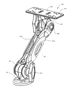
FIG. 1A is a perspective view depicting a first embodiment of a positionable
equipment
mount in accordance with the disclosure.
FIG. 1B is a view depicting the front of the positionable equipment out of
FIG. 1A.
FIG. 1C is a view depicting the right side of the positionable equipment out
of FIG. 1A.
5
CA 02932081 2016-06-03
FIG. 1D is a view depicting the back of the positionable equipment out of FIG.
1A.
FIG. 1E is a view depicting the left side of the positionable equipment out of
FIG. 1A.
FIG. IF is a view depicting the top of the positionable equipment out of FIG.
1A.
FIG. 1G is a view depicting the bottom of the positionable equipment out of
FIG. 1A.
FIG. 2A is a perspective view depicting a second embodiment of a positionable
equipment mount in accordance with the disclosure.
FIG. 2B is a view depicting the front of the positionable equipment out of
FIG. 2A.
FIG. 2C is a view depicting the right side of the positionable equipment out
of FIG. 2A.
FIG. 2D is a view depicting the back of the positionable equipment out of FIG.
2A.
FIG. 2E is a view depicting the left side of the positionable equipment out of
FIG. 2A.
FIG. 2F is a view depicting the top of the positionable equipment out of FIG.
2A.
FIG. 2G is a view depicting the bottom of the positionable equipment out of
FIG. 2A.
FIG. 3A is a view depicting the front of a platform mount, first ratcheting
pivot clamp
and a portion of a pair of bars in accordance with an embodiment of the
disclosure.
FIG. 3B is sectional view depicting a cross section of the platform mount and
the first
ratcheting pivot clamp of FIG. 3A.
FIG. 4A is a view depicting the front of an equipment mount, second ratcheting
pivot
clamp and a portion of the pair of bars in accordance with an embodiment of
the disclosure.
FIG. 4B is a sectional view depicting a cross-section of the equipment mount
and the
second ratcheting pivot clamp of FIG. 4A.
FIG. 5 is a top view depicting a mounting plate in accordance with an
embodiment of the
disclosure.
6
CA 02932081 2016-06-03
FIG. 6 is a perspective view depicting a left and right side portions of a
ratcheting pivot
clamp in accordance with an embodiment of the disclosure.
FIG. 7 is a perspective view depicting one side portion of a pivot clamp with
an
untapered shaft of a platform mount or equipment mount in accordance with an
embodiment of
the disclosure.
FIG. 8 is a detail view depicting sets of arcuate teeth of a ratcheting pivot
clamp meshing
with arcuate teeth of a shaft of a platform mount or equipment mount in
accordance with an
embodiment of the disclosure.
FIG. 9A is a view depicting the distal end of a shaft of a platform mount or
equipment
mount in accordance with an embodiment of the disclosure.
FIG. 9B is a view depicting the profile of the shaft of FIG. 9A.
FIG. 10 is a detail view depicting truncated teeth forming a part of a
ratcheting elbow
mount in accordance with an embodiment of the disclosure.
FIG. 11A is a perspective view depicting a base and a cross section of a
ratcheting pivot
clamp in accordance with an embodiment of the disclosure.
FIG. 11B is a perspective view depicting the base and ratcheting pivot clamp
of FIG.
11A.
FIG. 12 is a view depicting the base and ratcheting pivot clamp of FIG. 11A.
FIG. 13A is a view depicting a platform mount and a cross section of a
ratcheting pivot
clamp and bars in accordance with an embodiment of the disclosure.
FIG. 13B is perspective view depicting the platform mount and cross sections
of the
ratcheting pivot clamp and bars of FIG. 13A.
7
CA 02932081 2016-06-03
FIG. 14A is a perspective view depicting an assembled positionable equipment
mount in
accordance with the disclosure.
FIG. 14B is an exploded perspective view depicting the positionable equipment
mount of
FIG. 14A.
FIG. 15 is a perspective view depicting a partially disassembled tubular grip,
second
ratcheting pivot clamp and a portion of a pair of bars in accordance with an
embodiment of the
disclosure.
FIG. 16 is a perspective view depicting the tubular grip, second ratcheting
pivot clamp
and portion of a pair of bars of FIG. 15, wherein the tubular grip is
assembled.
FIG. 17 is a sectional, perspective view depicting a portion of an alternative
embodiment
of a tubular grip in accordance with the disclosure.
While embodiments of the disclosure are amenable to various modifications and
alternative forms, specifics thereof are shown by way of example in the
drawings and will be
described in detail. It should be understood, however, that the intention is
not to limit the
disclosure to the particular embodiments described. On the contrary, the
intention is to cover all
modifications, equivalents, and alternatives falling within the spirit and
scope of the disclosure as
defined by the appended claims.
DETAILED DESCRIPTION
8
CA 02932081 2016-06-03
Referring to FIGS. 1A-G, a positionable equipment mount 100 is depicted in
accordance
with an embodiment of the disclosure. Positionable equipment mount 100
generally includes a
platform mount 102, first ratcheting pivot clamp 104, second ratcheting pivot
clamp 106,
equipment mount 108, and a pair of bars 110A/110B. Referring to FIGS. 2A-G, a
positionable
equipment mount 100' according to a second embodiment of the disclosure is
depicted. One
difference between the embodiments depicted in FIG. 1A-G and FIG. 2A-G is the
length of bars
110A/110B and 110A7110B'.
In one embodiment, the positionable equipment mount 100 can be constructed of
a
corrosion resistant material, such that the positionable equipment mount 100
can resist corrosion
after being subjected to corrosive elements, such as saltwater. In one
embodiment, a company
logo 107, trademark or advertizing can be affixed or operably coupled to an
exterior surface of
the positionable equipment mount 100.
Referring to FIGS. 3A and 3B, closer views of the platform mount 102 and first
ratcheting pivot clamp 104 are depicted in accordance with an embodiment of
the disclosure.
Platform mount 102 can include a base 112 and a shaft 118 operably coupled to
one another.
Base 112 can be substantially planar on a bottom surface 114 or can be
contoured to conform to
a corresponding surface of a platform (not depicted). Base 112 can define one
or more bores 116
through which a fastener, such as a screw or bolt can pass. Bore 116 can
include an angular
shoulder to enable a portion of a head of a fastener to reside within bore
116.
In one embodiment, base 112 can define a bore 119 through which a fastener 117
can
pass. Bore 119 can include an angular shoulder to enable a portion of a head
of the fastener to
reside within bore 119. Bore 119 can vary in its diameter, such that in one
embodiment, bore 119
9
CA 02932081 2016-06-03
can be configured to receive at least a portion of a proximal end 127 of shaft
118. Fastener 117
can extend into a blind bore 125 defined within shaft 118, thereby selectively
coupling base 112
to shaft 118.
Shaft 118 can have a circumferential outer surface 120 defining a plurality of
splines or
teeth 122. In one embodiment, the circumferential outer surface 120 of shaft
118 can include a
reverse taper, such that a diameter of the distal end 126 of shaft 118 is
larger than a diameter of
the proximal end 127 of shaft 118. In such an embodiment, the tapering of
shaft 118 can inhibit
movement relative to and/or separation of the first ratcheting pivot clamp 104
from base 112
when exposed to vibration. In other embodiments (as depicted in FIG. 7), the
circumferential
outer surface 120 of shaft 118 is not tapered.
In one embodiment, the platform mount 102 and the first ratcheting pivot clamp
104 are
in abutting contact with one another along a plane substantially orthogonal to
the axis of shaft
118, such that shaft 118 completely resides within platform mount 102 and/or
first ratcheting
clamp 104. In such an embodiment, the abutting contact can serve to further
strengthen the
assembly, thereby inhibiting unwanted movement when exposed to vibration.
Referring to FIGS. 4A and 4B, closer views of the equipment mount 108 and the
second
ratcheting pivot clamp 106 are depicted in accordance with an embodiment of
the disclosure.
Equipment mount 108 can include a mounting plate 128, base 129 and shaft 136
operably
coupled to one another. Mounting plate 128 can have a substantially planar top
surface 130 or
can be contoured to conform to a corresponding surface of a piece of equipment
(not depicted).
Base 129 can be operably coupled to the bottom surface 131 of mounting plate
128. For
example, in one embodiment, mounting plate 128 defines one or more bores 133
(as depicted in
CA 02932081 2016-06-03
FIGS. 1A and 2A) through which fasteners 134 can pass. Fastener 134 can extend
into one or
more blind bores 135 defined in base 129, thereby selectively coupling
mounting plate 128 to
base 129.
In one embodiment, base 129 can define a bore 137 through which fastener 141
can pass.
Bore 137 can include an angular shoulder to enable a portion of a head of the
fastener to reside
within bore 137. Bore 137 can vary in its diameter, such that in one
embodiment, bore 137 can
be configured to receive at least a portion of the proximal end 145 of shaft
136. Fastener 141 can
extend into a blind bore 142 defined within shaft 136, thereby selectively
coupling base 126 to
shaft 136.
Shaft 136 can have a circumferential outer surface 138 defining a plurality of
teeth or
splines 140. In one embodiment, the circumferential outer surface 138 of shaft
136 can include a
reverse taper, such that a diameter of the distal end 144 of shaft 136 is
larger than a diameter of
the proximal and 145 of shaft 136. In such an embodiment, the tapering of
shaft 136 can inhibit
movement relative to and/or separation of the second ratcheting pivot clamp
106 from equipment
mount 108 when exposed to vibration. In other embodiments (as depicted in FIG.
7), the
circumferential outer surface 138 of shaft 136 is not tapered.
In one embodiment, the equipment mount 108 and the second ratcheting pivot
clamp 106
are in abutting contact with one another along a plane substantially
orthogonal to the axis of shaft
136, such that shaft 136 completely resides within equipment mount 108 and/or
second
ratcheting clamp 106. In such an embodiment, the abutting contact can serve to
further
strengthen the assembly, thereby inhibiting unwanted movement when exposed to
vibration.
11
CA 02932081 2016-06-03
Referring to FIG. 5 a top view of an exemplary mounting plate 128 is depicted
in
accordance with an embodiment of the disclosure. In one embodiment, mounting
plate 128 can
be substantially rectangular in shape, and can include a plurality of bores
132 through which one
or more fasteners (not depicted) can be used to secure a piece of equipment or
device to
mounting plate 128. The plurality of bores 132 can be configured in a pattern,
such that a variety
of devices can be coupled to mounting plate 128. In other embodiments,
mounting plate 128 can
be replaced with other attachments, selectively coupleable to other devices.
Referring to FIG. 6, a first ratcheting pivot clamp 104 is depicted in
accordance with an
embodiment of the disclosure. In one embodiment, the second ratcheting pivot
clamp 106 can be
substantially the same as the first ratcheting pivot clamp 104. First
ratcheting pivot clamp 104
can be comprised of two portions, a left side portion 146 and a right side
portion 148. Left side
portion 146 and right side portion can substantially mirror one another in
structure. In one
embodiment, the two portions of first ratcheting pivot clamp 104 are
positioned together when
positionable equipment mount 100 is assembled, thereby forming an internal
bore 150. Internal
bore 150 can be sized to accommodate a portion of shaft 118 or shaft 136, so
that either platform
mount 102 or equipment mount 108 can be operably coupled to ratcheting pivot
clamp 104.
In one embodiment, internal bore 150 includes an interior circumferential
surface 152.
With additional reference to FIG. 7, which depicts a left side 146 of a
ratcheting pivot clamp 104
and a shaft 118, the interior circumferential surface 152 can be characterized
by teeth 154
configured to mesh or interact with teeth 112 or teeth 140. In one embodiment,
teeth 154 can be
grouped together in distinct sets of teeth 156. Sets of teeth 156 can be
comprised of a plurality of
teeth 154, for example two or three teeth 154. Each set of teeth 156 can be
distinct from an
12
CA 02932081 2016-06-03
adjacent set of teeth 156 by separating the sets of teeth by a space wherein
no teeth 154 are
present. For example, in one embodiment, the entire interior circumferential
surface 152 can
include a plurality of distinct sets of teeth 154, for example two or four
sets of teeth 154, spaced
apart, with substantially smooth, toothless portions 158 on the interior
circumferential surface
152 positioned there between. In such an embodiment, by reducing the number of
teeth 154
required to be formed on first ratcheting pivot clamp 104, the production
requirements can be
reduced. Additionally, positioning fewer teeth 154 in distinct clusters or
sets 156 enables proper
ratcheting without the need to maintain the degree of precision in
manufacturing necessary to
ensure that every tooth 122/140 surrounding shaft 118/136 is able to mesh with
a corresponding
tooth of the internal bore 150.
Referring to FIG. 8, the interaction of teeth 154 with teeth 122 or teeth 140
is depicted in
accordance with an embodiment of the disclosure. In one embodiment, the
surfaces 160 of teeth
154 are arcuate in nature, including a filleted crown or peak 162. In one
embodiment, teeth 122
and teeth 140 can also include arcuate surfaces 164, including filleted crowns
or peaks 166. In
such an embodiment, the spaced apart sets of teeth 156 and the arcuate
surfaces 160 of the teeth
enable the equipment mount to be produced at increased tolerances. In such an
embodiment, the
arcuate or curved surfaces 160, 164 can meet across a line of intersection
168, instead of two flat
surfaces meeting across a plane of intersection, thereby providing less
opportunity for
imperfections to cause misalignment or non-uniform contact. Accordingly, the
arcuate surfaces
160, 164 of the teeth 122/140 enable increased tolerances, by requiring that a
minimized surface
area 168 along the arcuate surface 160 make contact with the corresponding
arcuate surface 164
of the corresponding tooth in order to ensure proper ratcheting, as well as a
tight fitting between
13
CA 02932081 2016-06-03
the clamp 104, 106 and the shaft 118, 136 along the axis of the shaft. The
arcuate surfaces 160,
164 of the teeth also enable smoother ratcheting, as the respective crowns
162, 166 are able to
traverse along the arcuate surfaces 160, 164 more easily. The arcuate surfaces
160, 164 also
minimizes the separation needed between the left and right side portions 146,
148 of pivot clamp
104, 106 to affect ratcheting adjustment.
Referring to FIGS. 9A-B, a distal end 127 of shaft 118 is depicted in
accordance with an
embodiment of the disclosure. In one embodiment, teeth 122 can be countersunk
into the surface
of shaft 118, such that the peak or crown 147 of teeth 122 do not extend
beyond the
circumferential outer surface 120 of shaft 118. In one embodiment, teeth 122
can include a
chamfered distal end 121.
Referring again to FIG. 6, the outer surface 170 of both sides 146, 148 of
pivot clamp 104
can include sets of teeth 172 comprising part of a ratcheting elbow mount 174.
Each set of teeth
172 can be configured in a ring surrounding a central bore 174. In one
embodiment, the width of
the base 178 of each tooth 176 can increase as its distance from the central
bore 174 increases.
Where the angle of the sides 180 of the teeth 176 remain constant, the crown
192 can be
truncated in order to prevent the peak or crown 182 furthest from the central
bore 174 from
having a higher elevation than the portion of the tooth 176 nearest to the
central bore 174. FIG.
10 depicts a closer view of the truncated teeth 172 in accordance with an
embodiment of the
disclosure. Such a configuration enables smoother ratcheting while minimizing
the separation
needed between bars 110A and 110B to affect ratcheting adjustment.
Referring to FIG. 11A-12, coupling of the shaft 136 of base 129 to the second
ratcheting
pivot clamp 106 is depicted in accordance with an embodiment of the
disclosure. In
14
CA 02932081 2016-06-03
embodiments where shaft 136 includes a reverse taper, the width of the base
139 of each tooth
140 can increase in size along the length of shaft 136, such that the base 139
is narrowest in
proximity to the proximal end 145 of shaft 136 and widest in proximity to the
distal end 144 of
shaft 136. Where the angle of the sides 143 of the teeth 140 remain constant,
the crown 147 can
be truncated in order to prevent the peak or crown 147 nearest to the distal
end 144 from having
a higher elevation than the portion of the teeth 140 nearest to the proximal
end 145.
In one embodiment, the entire peak or crown 147 along the length of teeth 140
can be
truncated, such that one or more voids 149 exist between the one or more teeth
140 of shaft 136
and the ratcheting pivot clamp 104, 106 along the length of shaft 136, when
the shaft 136 is
coupled to the ratcheting pivot clamp 104, 106. In such an environment, the
one or more voids
149 inhibit interference of the peak or crown 147 with the internal
circumferential surface 152 of
the ratcheting pivot clamp 104, 106, thereby improving the contact between the
faces or sides
143 of the teeth 140 and the respective faces or sides of teeth 154 of the
ratcheting pivot clamp
104, 106. In one embodiment, the peak or crown of teeth 154 of the ratcheting
pivot clamp 104,
106 can also be truncated.
In one embodiment, the internal bore 150 can vary in diameter, such that the
internal
circumferential surface 152, where no teeth 154 are present, can be sized to
fit with the truncated
peak or crown 147 of the teeth 140 of shaft 136. Such a configuration further
aids in
immobilizing shaft 136 relative to the ratcheting pivot clamp 104, 106 when
coupled together,
particularly when exposed to vibration.
Referring to FIGS. 13A-B, cross-sectional views of the first ratcheting pivot
clamp 104
coupled with platform mount 102 and bars 110A/B are depicted in accordance
with an
CA 02932081 2016-06-03
embodiment of the disclosure. In this embodiment, the tightening of hand screw
190 can cause
the left side 146 and the right side 148 of the first ratcheting pivot clamp
104 to squeeze the shaft
118 of platform mount 102, and can cause the bars 110A/B to squeeze the first
ratcheting of the
clamp 104, thereby locking each of these components in position relative to
one another.
Referring to FIGS. 14A-B, assembled and exploded views of a positionable
equipment
mount 100 are depicted in accordance with an embodiment of the disclosure. The
various
components of equipment mount 100 can be assembled via fastener 184, such as a
threaded bolt.
In one embodiment, fastener 184 traverses through: a bore 186A in the right
bar of the pair of
bars 110A; the centralized bore 174A of right side portion 148 of ratcheting
pivot clamp; the
centralized bore 174B of left side portion 148 of ratcheting pivot clamp; a
bore 186B in the left
bar of the pair of bars 110A; a spring 188; and a washer 189. In one
embodiment, the end of
fastener 184 is secured via a knob or hand screw 190. In one embodiment, bar
110 can include a
blind bore 192 sized to accommodate the head 194 of fastener 184 for
inhibiting the fastener 184
from spinning when the head 194 is positioned at least partly within blind
bore 192. For
example, in one embodiment, blind bore 192 can be configured to at least
partially accommodate
a hexagon bolt head therein.
A spring 188 can be configured to exert a biasing force to the assembly,
thereby forcing
the two halves of the bar 110 together when the equipment mount 100 is
assembled. This biasing
force enables proper ratcheting of the elbow mounts 174 and the ratcheting
pivot clamp when the
hand screw 190 is partially loosened.
The right and left portions 146, 148 can each include one or more bores 194
sized to
accommodate one or more springs 196. Springs 196 can be configured to exert a
biasing force to
16
CA 02932081 2016-06-03
the right and left portions 146, 148, thereby forcing the right and left
portions 146, 148 apart
when the equipment mount 100 is assembled. This biasing force eases proper
ratcheting of the
ratcheting pivot clamp when the hand screw 190 is loosened.
Referring to FIGS. 15-17, a tubular grip 202 is depicted in accordance with an
embodiment of the disclosure. In one embodiment, the mounting plate 128 and
base 129 of the
equipment mount 108 can be replaced with tubular grip 202. Tubular grip 202
can be configured
to mount pieces of equipment having a tubular profile, such as a trolling
motor.
Tubular grip 202 can be comprised of a lower portion 204 and an upper portion
206
pivotably coupled to one another by hinge 208, thereby enabling the lower
portion 204 and the
upper portion 206 to pivot relative to one another, such that a piece of
equipment can be inserted
therebetween. In one embodiment, the lower portion 204 and the upper portion
206 can overlap
via a tongue and groove assembly for improved strength and durability. Similar
to base 129, the
lower portion 204 can define a bore 210 configured to accommodate at least a
portion of shaft
136. A fastener 212 can be configured to secure lower portion 204 to shaft
136.
In one embodiment, the lower portion 204 and the upper portion 206 can include
a
recessed portion 214 configured to retain insert grip 216. Insert grip 216 can
be configured to
improve the gripping surface between tubular grip 202 and the piece of
equipment. For example,
in one embodiment, insert grip 216 is constructed of rubber and includes a
plurality of treads for
improved positioning within recessed portion 214 while maintaining surface
contact with the
piece of equipment.
In one embodiment, tubular grip 202 can include a lock 218, configured to lock
the lower
portion 204 and the upper portion 206 relative to one another in the equipment
gripping position.
17
CA 02932081 2016-06-03
For example, lock 218 can be positioned opposite hinge 208. A pin 220 can be
used to secure
lock 218 in the equipment gripping position. In one embodiment, a tether 222
can couple pin 220
to either lower portion 204 or upper portion 206.
In operation, a user mounts the platform mount 102 to a platform and the
equipment
mount 108 to a piece of equipment desired to be mounted to the platform. With
the fastener 184
in place and the hand screw 190 loosened, the platform mount 102 and the
equipment mount 108
can be inserted into the respective internal bores 150 of the first and second
ratcheting pivot
clamps 104, 106. The position of the piece of equipment relative to the
platform can be adjusted
by ratcheting the pivot clamps 104, 106 and the elbow mounts 174 into their
respective desired
positions. The position can be secured by tightening the knob or hand screw
190.
When a user desires to adjust the position of the piece of equipment relative
to the
platform, the user can loosen the hand screw 190, thereby permitting the pivot
clamp 104, 106
and elbow mounts 174 associated with that hand screw 190 to be ratcheted into
a desired
position. The disclosed groupings of distinct sets of teeth 156, arcuate
surfaces of the teeth 160
and truncated crowns of the teeth 182 enable proper ratcheting with minimized
gaps between
components. The minimized gaps reduce the amount that hand screw 190 needs to
be loosened,
thereby simplifying the task of adjusting the equipment mount 100. The spring
188 included in
the assembly exerts a biasing force to enable the equipment mount 100 to
maintain its position
while being adjusted, thereby reducing the need for the user to support the
equipment during
adjustment. When the position of the piece of equipment has been properly
adjusted relative to
the platform, hand screw 190 can be tightened. In this manner, the position of
the piece of
18
CA 02932081 2016-06-03
equipment is locked in place relative to the platform, such that unwanted
movement of the piece
of equipment is reduced or inhibited, particularly when subjected to heavy
vibration and shock.
It should be understood that the individual steps used in the methods of the
present
teachings may be performed in any order and/or simultaneously, as long as the
teaching remains
operable. Furthermore, it should be understood that the apparatus and methods
of the present
teachings can include any number, or all, of the described embodiments, as
long as the teaching
remains operable.
Persons of ordinary skill in the relevant arts will recognize that embodiments
may
comprise fewer features than illustrated in any individual embodiment
described above. The
embodiments described herein are not meant to be an exhaustive presentation of
the ways in
which the various features may be combined. Accordingly, the embodiments are
not mutually
exclusive combinations of features; rather, embodiments can comprise a
combination of different
individual features selected from different individual embodiments, as
understood by persons of
ordinary skill in the art. Moreover, elements described with respect to one
embodiment can be
implemented in other embodiments even when not described in such embodiments
unless
otherwise noted. Although a dependent claim may refer in the claims to a
specific combination
with one or more other claims, other embodiments can also include a
combination of the
dependent claim with the subject matter of each other dependent claim or a
combination of one
or more features with other dependent or independent claims. Such combinations
are proposed
herein unless it is stated that a specific combination is not intended.
Furthermore, it is intended
also to include features of a claim in any other independent claim even if
this claim is not
directly made dependent to the independent claim.
19
CA 02932081 2016-06-03
Moreover, reference in the specification to "one embodiment," "an embodiment,"
or
"some embodiments" means that a particular feature, structure, or
characteristic, described in
connection with the embodiment, is included in at least one embodiment of the
teaching. The
appearances of the phrase "in one embodiment" in various places in the
specification are not
necessarily all referring to the same embodiment.
Any incorporation by reference of documents above is limited such that no
subject matter
is incorporated that is contrary to the explicit disclosure herein. Any
incorporation by reference
of documents above is further limited such that no claims included in the
documents are
incorporated by reference herein. Any incorporation by reference of documents
above is yet
further limited such that any definitions provided in the documents are not
incorporated by
reference herein unless expressly included herein.
For purposes of interpreting the claims, it is expressly intended that the
provisions of
Section 112, sixth paragraph of 35 U.S.C. are not to be invoked unless the
specific terms "means
for" or "step for" are recited in a claim.
20