Note: Descriptions are shown in the official language in which they were submitted.
CHECK VALVE
RELATED APPLICATIONS
[0001] This application claims the benefit of U.S. Provisional
Application No.
61/914,892, filed December 11, 2013, titled CHECK VALVE.
BACKGROUND
Field of the Disclosure
[0002] A variety of devices and techniques exist for the
manipulation of fluids in
hospitals and medical settings, and in particular the selective facilitation
of fluid movement to or
from patients or to or from a fluid flow line. Fluid flow lines rely on a
variety of connectors to help
develop preferred flow characteristics or access points. Many connectors
include check valves.
Description of the Related Art
[0003] Current fluid flow systems, medical connectors, and check
valves have
various limitations and disadvantages and a need exists for further
improvement.
SUMMARY OF THE DISCLOSURE
[0004] A variety of fluid flow lines and systems are used in
hospitals and medical
settings for the selective facilitation of fluid movement to or from patients.
For example, central
venous catheters can be used to administer IV fluids, various medications or
blood products, and/or
parenteral nutrition. In some embodiments, medical connectors can be provided
on one end of a
flow line to allow for periodic access to a flow line or for application of
different inputs to the flow
line. Generally, these structures require valves to allow fluid to enter the
main flow line while
preventing retrograde flow.
[0005] In certain situations, it may be desirable to provide
multiple connections to
a flow line into a patient's blood stream. This can allow for easy connection
to multiple fluid or
medication sources. This is particularly useful in treatments that require
multiple inputs, such as
chemotherapy. When multiple connections are desired, a manifold, extension
set, or other multi-
input structure can be used. These structures also require valves to allow
fluid to enter the main
flow line but
-1-
CA 2932124 2019-11-27
CA 02932124 2016-05-30
WO 2015/088862
PCT1US2014/068455
that preferably prevent retrograde flow. In various embodiments described
herein, such
valves can be designed to maximize efficiency and desired flow rates and flow
characteristics while still providing a check on retrograde flow. In some
situations, it
may be desirable to provide a single connection point with one way flow.
100061 In various embodiments, a medical check valve for use in a
medical
device to provide one-way fluid flow between a first fluid location and a
second fluid
location can include a flexible diaphragm. having a top surface, a bottom
surface, and a
side wall between the top surface and the bottom surface, and a first support
member
extending from the bottom surface of the flexible diaphragm and a second
support
member extending from the bottom surface of the flexible diaphragm, the first
support
member and second support member positioned to define a line of or axis of
symmetry
that bisects the bottom surface without passing through the first support
member or the
second support member. The flexible diaphragm can have a first position in
which the
top surface is generally planar and is configured to seal against a fluid
opening and a
second position in which the top surface of the diaphragm is curved generally
around the
line of symmetry and is configured to be displaced from the fluid opening.
100071 in some embodiments, the line of symmetry can be the only line
of
symmetry that bisects the bottom surface without passing through the first
support
member or the second support member, hi some embodiments, the flexible
diaphragm
can be a disc. In some embodiments, the support members can be positioned 180
degrees
apart about the disc. In some embodiments, the flexible diaphragm can be
nonperforate.
In some embodiments, the flexible diaphragm, the first support member, and the
second
support member can be integrally formed and/or molded into a single unitary
piece.
100081 In some embodiments, the diaphragm can be configured to move
from
the first position to the second position at varying amounts of pressure. For
example, in
some embodiments a net pressure of less than 3psi on the top surface of the
flexible
diaphragm is sufficient to move the diaphragm from the first position to the
second
position. In some embodiments, a net pressure of less than !psi on the top
surface of the
flexible diaphragm is sufficient to move the diaphragm from the first position
to the
second position. In some embodiments, a positive net pressure on the bottom
surface of
the flexible diaphragm is needed to maintain the flexible diaphragm in the
first position.
100091 In various embodiments, a medical manifold for use in providing
access to a fluid flow path can include a housing having a first port, a
second port, a first
-2-
channel connecting the first port and the second port and defining a first
flow path, and a third port
having a recess in an outer wall of the housing and a second channel fluidly
connecting the recess
and the first flow path. The manifold can also include a valve member having a
diaphragm and a
plurality of support members configured to be positioned in the recess to
thereby define a space
between a bottom wall of the recess and the diaphragm. The manifold can also
include a medical
connector configured to attach to the third port, wherein the valve member in
a closed position is
configured to seal against an opening into the medical connector and the valve
member in an open
position is configured to allow fluid to flow from the medical connector, past
the valve member,
through the second channel, and into the first flow path.
[0010] In some embodiments, an outer wall of the recess can be
cylindrical. In
some embodiments, an outer wall of the recess can include multiple walls. In
some embodiments,
the third port can have at least two projections extending from the bottom
wall of the recess and
adjacent the second channel, wherein the projections define an outer channel
between the
projections and an outer wall of the recess and at least two transverse
channels between the
projections. In some embodiments, the plurality of support members can be
configured to be
positioned on at least two of the projections. In such embodiments, the valve
member in an open
position is configured to allow fluid to flow from the medical connector, past
the valve member to
the outer channel, through the transverse channels, and into the second
channel.
[0011] In some embodiments, the valve member can be biased toward
the closed
position. In some embodiments, the valve member can be configured to move from
the closed to
the open position as a result of pressure from fluid in the medical connector.
In some embodiments,
the housing can be monolithic. In some embodiments, a net pressure of less
than 3psi on the valve
member can be sufficient to move the valve member from the closed position to
the open position.
In various embodiments, a medical manifold for use in providing access to a
fluid flow
path can include a first port, a second port, a first channel connecting the
first port and the second
port and defining a first flow path, and a housing having a third port in an
outer wall of the housing
and a second channel fluidly connecting the third port and the first flow
path. The manifold can
also include a valve member having a diaphragm and a plurality of support
members configured
to be positioned in the third port to thereby define a space between a bottom
wall of the third port
and the diaphragm. The manifold
-3-
CA 2932124 2019-11-27
CA 02932124 2016-05-30
WO 2015/088862
PCT1US2014/068455
can also include a medical connector configured to attach to the third port,
wherein the
valve member in a closed position is configured to seal against an opening
into the
medical connector and the valve member in an open position is configured to
allow fluid
to flow from the medical connector, past the valve member, through the second
channel,
and into the first flow path.
In some embodiments, the third port further includes at least two projections
extending from the bottom wall of the third port and adjacent the second
channel, wherein
the projections define at least two transverse channels between the
projections. The
plurality of support members may be configured to be positioned on at least
two of the
projections. In some embodiments, the third port of the medical manifold
includes a
recess and the projections extend from the bottom wall of the recess. A wall
surrounding
the recess may extend outward from the housing and a portion of the medical
connector
may be configured to surround at least a portion of the wall. In some
embodiments, the
medical connector is sonically welded to the third port.
In some embodiments, an outer wall of the third port can be cylindrical. In
some
embodiments, an outer wall of the third port can include multiple walls. In
some
embodiments, the third port can have at least two projections extending from
the bottom
wall of the third port and adjacent the second channel, wherein the
projections define an
outer channel between the projections and an outer wall of the third port and
at least two
transverse channels between the projections. In some embodiments, the
plurality of
support members can be configured to be positioned on at least two of the
projections.
In such embodiments, the valve member in an open. position is configured to
allow fluid
to flow from the medical connector, past the valve member to the outer
channel, through
the transverse channels, and into the second channel.
In various embodiments, a medical manifold for use in providing access to a
fluid
flow path can include a first port, a second port, a first channel connecting
the first port
and the second port and defining a first flow path, and a housing having a
third port in an
outer wall of the housing and a second channel fluidly connecting the third
port and the
first flow path. The manifold can also include a valve member having a
diaphragm and a
plurality of support members configured to be positioned in the third port to
thereby
defm.e a space between a bottom. wall of the third port and the diaphragm. The
manifold
can also include a medical connector configured to attach to the third port,
wherein the
valve member in a closed position is configured to seal against an opening
into the
-4-
medical connector and the valve member in an open position is configured to
allow fluid to flow
from the medical connector, past the valve member, through the second channel,
and into the first
flow path. The medical manifold can also include a second housing including a
fourth port with a
third channel fluidly connecting the fourth port and the first flow path. In
some embodiments, the
manifold can include a second valve member with a diaphragm and a plurality of
support members
configured to be positioned in the fourth port to thereby define a space
between a bottom wall of
the fourth port and the diaphragm. Some manifolds can include a second medical
connector
configured to attach to the fourth port, wherein the second valve member in a
closed position is
configured to seal against an opening into the second medical connector and
the second valve
member in an open position is configured to allow fluid to flow from the
second medical connector,
past the second valve member, through the third channel, and into the first
flow path. In some
embodiments, the first and second housings are monolithic while in other
embodiments, wherein
the first and second housings are joined by a flexible connecting element.
[0011a] According to an aspect, is a medical check valve for use in a
medical
device to provide one-way fluid flow between a first fluid location and a
second fluid location,
said check valve comprising:
a flexible diaphragm comprising a top surface, a bottom surface, and a side
wall between
the top surface and the bottom surface; and
a first support member extending from the bottom surface of the flexible
diaphragm and a
second support member extending from the bottom surface of the flexible
diaphragm, the first
support member and second support member positioned to define a line of
symmetry that bisects
the bottom surface without passing through the first support member or the
second support
member,
wherein the flexible diaphragm has a first position in which the top surface
is generally
planar and is configured to seal against a fluid opening and a second position
in which the top
surface of the diaphragm is curved downward around the line of symmetry
thereby creating a
concavity on the top surface of the diaphragm, the diaphragm and is configured
to be displaced
from the fluid opening in the second position.
[0011b] In accordance with a further aspect, is a medical manifold
for use in
providing access to a fluid flow path, said medical manifold comprising:
a first port;
-5-
Date Recue/Date Received 2022-05-04
a second port a first channel connecting the first port and the second port
and defining a
first flow path;
a housing comprising:
a third port comprising a second channel fluidly connecting the third port and
the
first flow path;
a valve member comprising a diaphragm and a plurality of support members
configured to be positioned in the third port to thereby define a space
between a bottom
wall of the third port and the diaphragm;
a medical connector configured to attach to the third port, wherein the valve
member in a closed position is configured to seal against an opening into the
medical
connector and the valve member in an open position is configured to allow
fluid to flow
from the medical connector, past the valve member, through the second channel,
and into
the first flow path.
BRIEF DESCRIPTION OF THE DRAWINGS
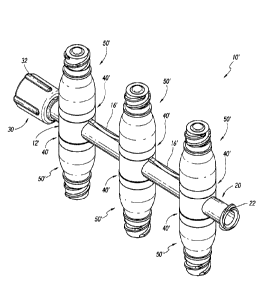
[0012] FIG.1 is a perspective view of one embodiment of a manifold.
FIG. 1A is a perspective view of an embodiment of a manifold with a modified
projection
attachment.
FIG.1B is a perspective view of an embodiment of a manifold component.
[0013] FIG.2 is a perspective view of one embodiment of a manifold.
FIG. 2A is a perspective view of an embodiment of a manifold with a modified
projection
attachment.
FIG.2B is a perspective view of an embodiment of a manifold component.
[0014] FIG.3 is a cross-sectional view of the manifold of Figure 1.
FIG.3A is a cross-sectional view of the manifold of Figure 1A.
FIG.3B is a cross-sectional view of the manifold of Figure 1B.
[0015] FIG.4 is a cross-sectional view of the manifold of Figure 2.
FIG.4A is a cross-sectional view of the manifold of Figure 2A.
FIG.4B is a cross-sectional view of the manifold of Figure 2B.
[0016] FIG. 5 is a perspective view of one embodiment of a port of a manifold.
FIG.5A is a perspective view of an embodiment of a port of a manifold.
-5a-
Date Recue/Date Received 2022-05-04
CA 02932124 2016-05-30
WO 2015/088862
PCT1US2014/068455
[00171 FIG. 6 is a top view of the port of Figure 5.
[00181 FIG. 7 is a bottom perspective view of one embodiment of a
check
valve.
100191 FIG. 8 is a top perspective view of the check valve of Figure
7.
100201 FIG. 9 is a bottom view of the check valve of Figure 8.
100211 FIG. 10 is a side view of the check valve of Figure 9.
100221 FIG. 11A is a cross-sectional view of one embodiment of a port
of a
manifold with a check valve.
100231 FIG. 11B is a cross-sectional. view of one embodiment of a port
of a
manifold with an attached medical connector, with a check valve not shown.
100241 FIG. 12A is a cross-sectional view of one embodiment of a port
of a
manifold with an attached medical connector and a check valve in a closed
position.
100251 FIG. 12B is a cross-sectional view of the embodiment of Figure
12A
with the check valve in an open position.
[00261 FIG. 13A is a cross-sectional view of one embodiment of a port
of a
manifold with an attached medical connector and a check valve in a closed
position.
[00271 FIG. 13B is a cross-sectional view of the embodiment of Figure
13A
with the check valve in an open position.
DETAILED DESCRIPTION OF THE PREFERRED EMBODIMENTS
[00281 With reference to the attached figures, certain embodiments and
examples of fluid flow systems, medical connectors, and valves will now be
described.
Various embodiments of check valves described herein are with reference to a
manifold
or extension set, but they are not so limited. In some aspects, they can be
applied to any
system to provide for one-way flow between a medical connector and a fluid
flow line,
such as in, for example, IV sets, stopcocks or other branched connectors
including y-site
connectors, and other systems. As used herein, the term "fluid" refers to
either gases or
liquids.
100291 FIG. 1 illustrates an embodiment of a manifold 10 that can be
used to
provide access to a fluid flow path. The manifold can include a manifold
housing 12 that
can include a first port 20 and a second port 30. In some embodiments, the
housing can
be one integral piece, and in some embodiments it can include multiple pieces
such that
the manifold includes first and second ports connected by a fluid path, but
the ports are
-6-
CA 02932124 2016-05-30
WO 2015/088862
PCT1US2014/068455
connected by separately formed units, for example tubes, to the housing. In
some
embodiments, multiple housings may be connected between the first and second
ports.
Preferably, even when connected by flexible joints, the manifold in a resting
position
defines a generally linear fluid path between the first and second ports with
one or more
ports branching off that path. In some embodiments, those one or more ports
branch off
at about 90 degrees from the flow path between the first and second ports. The
manifold
can be inserted into a fluid flow line with the first port 20 configured to
attach to one end
of the line and the second port 30 configured to attach to a second end of the
line. The
ports can be configured to accommodate any standard medical connector or
implement,
and can be adapted to conform with ANSI (American National Standards
Institute) or
other applicable standards. In some embodiments, different ports can also be
configured
to have nonstandard connections.
[00301 In some embodiments, a first port 20 can. have a threaded end
22 that
can be used to connect to a threaded medical connector. In some embodiments, a
second
port 30 can have a male luer lock 32, including a tapered cannula 34 (visible
in FIGS. 3
and 4).
[00311 in some embodiments, the manifold 10 can include a plurality of
access ports 40, described and illustrated in more detail below. The access
ports can be
adapted to connect Of attach to a variety of types of medical tioalleciOrs 50.
In some
embodiments, as illustrated, a medical connector 50 can be a needleless
connector. In the
illustrated embodiment, the manifold includes six medical connectors 50, three
on a first
side of the manifold and three on a second side of the manifold.
In various embodiments, a manifold can have varying numbers of access ports
and
medical connectors. For example, FIG. 2 illustrates an embodiment of a
manifold 10"
that has three access ports and medical connectors 50 on one side of the
manifold.
Housing 12¨ includes joints 16¨ and can include an extended portion or fin 13
that
may be positioned on the side opposite the medical connectors. Fin 13" ' can
be provided
to add stability to the manifold 10¨ and may be configured to facilitate the
handling or
control by a nurse or other user of the manifold 10¨ during use or to attach
the manifold
10' to a convenient resting place. FIG. 2A shows an alternative manifold 10¨
also
including three access ports and medical connectors 50' on one side. Housing
12"
includes joints 16¨ and can include an extended portion or fm 13" that may be
positioned on the side opposite the medical connectors. Fin 13" can be
provided to add
-7-
CA 02932124 2016-05-30
WO 2015/088862
PCT1US2014/068455
stability to the manifold 10¨ and may be configured to facilitate the handling
or control
by a nurse or other user of the manifold 10¨ during use or to attach the
manifold 10¨
to a convenient resting place. As shown, joints 16¨ may include shallow curved
portions as compared to the curved portions on joints 16" ' shown in FIG. 2.
Curved
portions and other structures can be used to change the strength of the
housing and to
provide a convenient place to hold the manifold.
Other combinations of ports are also possible. For example, FIG. I B shows a
manifold 10" including two double housings 12". FIG. 2B shows a manifold 10
including two single housings 12 .............................. . As discussed
above, a single manifold may include
various combinations of such housings as desired.
Embodiments of the invention may provide various ways to connect medical
connectors to the housing ports, as discussed in greater detail below. For
example, FIG.
IA shows a six port manifold 10' with alternative ports 40' and modified
connectors 50'.
As shown, in some embodiments various modifications can be made to the
connecting portions or joints 16 between the ports. For example, FIG. 1 shows
a first
version of the joints 16 while FIG. 1A shows an alternative joint 16' that
includes shallow
arched or curved portions. As shown in FIG. 1B, in some embodiments, rather
than
having a single housing 12 (see, for example, FIGS. 1 and IA), a manifold 10"
can have
a plurality of housings 12" joined by a flexible connecting portion, for
example, tubing.
Thus, for example, in some embodiments the joints 16" of the manifolds that
connect
housings having medical connectors or pairs of medical connectors can be
formed of
tubing.
FIG. 18 shows two double housings 12". Various combinations are also
possible. In some embodiments, a single housing 12" with double ports may be
provided
and can. be accessed by first and second ports 20' and 30. First port 20' may
be similar to
first port 20, except the rigid portion may be longer to accommodate the
appropriate
section of a medical implement, for example, a male Wen In some embodiments,
the
manifold may include 3 or more housings 12" with corresponding medical
connectors.
Accordingly, the manifold can readily customized to provide an appropriate
solution
according to a user's needs. In addition, the manifold may include a
combination of
housings and ports, for example, a manifold may be provided with one or more
double
housing 12" and one or more single housings 12 ................ (see FIG.
2B). Providing flexible
joints allows the manifold to flex and adapt to the needs of the user. For
example, a port
-8-
may be rotated to ease access while minimizing the movement of other ports
that may already be
accessed by various medical devices. The flexible joints of the manifold are
permanently attached,
for example by bonding or glueing, to their respective housings and ports such
that the manifold
is a single unity.
[0032] In some embodiments, various ports may remain connected or
unconnected
to one or more fluid sources and/or to a patient. For example, in some
embodiments, one of the
first port 20 and second port 30 can be connected to a patient, the other of
the first port and second
port may be sealed (such as with a medical connector 50 or a similar sealed
access port) and
unconnected to a fluid source, and one or more of the medical connectors 50
can be connected to
a fluid source for the patient. In some embodiments, embodiments of the
manifold can be used
without a patient, for example, to combine one or more fluids into a single
fluid receptacle (not
shown). Accordingly, embodiments of the invention need not be used in direct
connection with a
patient.
[0033] FIGS. 3 and 4 illustrate cross-sectional views of the
manifolds of FIGS. 1
and 2, respectively. As illustrated, medical connectors 50 can attach to the
manifold at access ports
40. In some embodiments, a medical connector 50 can be a needleless medical
connector that
includes a connector body 60, a connector base 70, and a connector valve
member 80 positioned
at least partially within the connector body 60. Further details regarding
needless medical
connectors that can be used are found in U.S. Provisional Patent Application
No. 61/914680, filed
December 11,2013.
[0034] In some embodiments, other types of medical connectors or of
needleless
medical connectors can be attached to the access ports 40 of the manifolds.
These can include
connectors configured to receive syringes and connectors of varying designs.
In some
embodiments, a manifold can include one or more of a first type of medical
connector and one or
more of a second type of medical connector. In some embodiments, a manifold
can include more
than two types of medical connectors. In some embodiments, first port 20
and/or second port 30
may include sealed access ports that are similar to those that may be used for
access ports 40.
Similarly, they can include check valves such as those described herein.
-9-
Date Recue/Date Received 2021-04-19
CA 02932124 2016-05-30
WO 2015/088862
PCT1US2014/068455
FIGS. 3A and 4A illustrate cross-sectional views of the manifolds of FIGS. IA
and 2A, respectively. As illustrated, medical connectors 50' can attach to the
manifold at
access ports 40'. Similar to medical connector 50 discussed above, medical
connector
50' can be a needleless medical connector that includes a connector body 60',
a connector
base 70', and a connector valve member 80' positioned at least partially
within the
connector body 60'. In some embodiments, the manifolds 10' and 10¨ shown in
FIGS.
IA, 3A and 2A, 4A, respectively, can be modified to incorporate medical
connectors 50.
FIGS. 3B and 4B illustrate cross-sectional views components of the manifolds
shown FIGS. 1B and 2B, respectively. As illustrated, medical connectors 50'
can attach
to the manifold at access ports 40'. In some embodiments, the manifolds 10¨
and 10
shown in FIGS. I B, 3B and 2B, 4B, respectively, can be modified to
incorporate medical
connectors 50.
Medical connectors can be attached to the housings in a variety of ways. As
shown in FIG. 4B for example, medical connector 50' can incorporate features
to
facilitate sonic welding of the connector to the housing. In the illustrated
embodiment,
medical connector 50' is attached to housing 12 ............... by way of
connector base 70'. An
inner recess in connector base 70' is sized to receive projecting ring 44' of
access port
40'. Projecting ring can help stabilize medical connector 50' on housing 12
.
100351 Preferably,
the medical connectors 50 can each provide a fluid flow
path from a medical implement attached to the medical connector, through the
medical
connector, into the access port 40 and through an access channel 42 into a
main channel
14 of the manifold. In a similar fashion, medical connectors 50' can each
provide a fluid
flow path from a medical implement attached to the medical connector, through
the
medical connector, and into the access port 40' and through an access channel
42' into a
main channel 14 of the manifold. Preferably, the access port 40 or 40' can
include a one-
way valve Or check valve 100, which can allow fluid to flow through the
medical
connector into the main channel 14, but prevent fluid from flowing from the
main channel
back into the medical connector. Various embodiments of a check valve 100 are
described in more detail below.
[00361 FIG. 5
illustrates a perspective view of an access port 40 of a manifold.
The access port can include a recess 140 with an outer wall 142 and a base
144. The
recess is preferably cylindrical such that the outer wall is cylindrical,
although in some
embodiments it can have other shapes. An access channel 42 can connect the
base 144 to
-10-
CA 02932124 2016-05-30
WO 2015/088862
PCT1US2014/068455
a main channel of a manifold or other device. A plurality of protrusions 150
can extend
upward from the base of the recess 140. The protrusions can each include a
central wall
152 that faces the access channel 42, side walls 154, and an outer wall 156.
In some
embodiments, the central walls 152 of the protrusions can be flush with a side
wall 43 of
the access channel 42. In some embodiments, the central walls 152 can define a
continuous surface with a side wall 43 of the access channel.
100371 Preferably, the outer walls 156 of the protrusion do not extend
all the
way to the outer wall 142 of the access port recess 140, thereby defining an
outer channel
48 between the protrusions and the outer wall 142. The protrusions can be
spaced from
each other to define transverse channels 46 between them. that can connect the
outer
channel 48 to the access channel 42. In some embodiments, the access port 40
can also
include an outer recess 44 that can be used to help seat a medical connector
attached to
the access port.
100381 FIG. 5A illustrates a perspective view of an access port 40' of
a
manifold which is similar in many respects to access port 40. The access port
can include
a recess 140' with an outer wall 142' and a base 144'. The recess is
preferably
cylindrical such that the outer wall is cylindrical, although in some
embodiments it can
have other shapes. An access channel 42' can connect the base 144' to a main
channel of
a manifold or other device. A plurality of protrusions 150' can extend upward
from the
base of the recess 140'. The protrusions can each include a central wall 152'
that faces
the access channel 42' and side walls 154'. In some embodiments, the central
walls 152'
of the protrusions can be recessed back from a side wall 43' of the access
channel 42' as
shown. The transition from the central walls 152' to the side wall 43' may be
curved to
facilitate fluid flow there through. In some embodiments, the central walls
152' can
define a continuous surface with a side wall 43' of the access channel. As
shown, the
protrusions 150' may be formed flush with the outer wall 142' though in some
embodiments, they may be off set from the wall and provide an outer fluid
channel like
channel 48 shown in FIG. 5. Access port 40' may also include projecting ring
44' that
may be used to stabilize connector 50' as shown.
FIG. 6 illustrates a top view of an access port 40. in the embodiment of FIG.
6,
the access port includes four protrusions 150 that are spaced symmetrically
about a center
of the access channel 42. Preferably, side walls 154 of the protrusions are
generally
parallel to each other. In some embodiments, however, the side walls can angle
toward
-11-
CA 02932124 2016-05-30
WO 2015/088862
PCT1US2014/068455
each other as they get closer to the center of the access channel 42, and in
some
embodiments the side walls can diverge as they get closer toward the center of
the access
channel. In some embodiments, the access port 40 can include varying numbers
of
protrusions 50, such as 2, 3, 5, 6, or more protrusions. The protrusions can
be
symmetrically spaced about the access channel 42 or spaced about the access
channel in
other arrangements.
(00391 In. some embodiments, various components of the access port 40
can
be centered around the access channel 42. In some embodiments, the access
channel
itself can be generally cylindrical and have a radius RI, as illustrated. In
some
embodiments the outer wall 142 of the access port recess 140 can have a radius
R3
centered on the center of the access channel 42. Similarly, the outer walls
156 of the
protrusions 150 can be curved and have a radius of curvature R2 centered on
the center of
the access channel 42. Similar radius of curvatures may be defined by access
port 40'. In
the illustrated embodiment, R2' and R3' of access port 40' would be equal.
[00401 When fluid flows through a medical connector attached to an
access
port 40, it will flow through the channels of the access port in order to
reach a main
channel of a fluid flow line. In various embodiments, the sizing of certain
components of
the access port can affect the size of the outer channel 48, transverse
channels 46, and/or
access channel 42, and therefore can affect the fluid flow characteristics of
the access port
40.
100411 Thus, for example, in some embodiments the ratio of the radius
R3 of
the access port recess 140 to the radius R2 of the outer walls 156 of
protrusions 150 may
vary. In some embodiments, the ratio of R3 to R2 can be between approximately
0.5 and
2Ø In some embodiments, the ratio of R3 to R2 can be between approximately
0.8 and
1.7. In some embodiments, the ratio of R3 to R2 can be between approximately
1.0 and
1.5. In some embodiments, the ratio of R3 to R2 can be between approximately
1.1 and
1.3. These ratios are also applicable to access port 40'.
(00421 Similarly, in some embodiments the ratio of the radius R3 of
the access
port recess 140 to the radius RI of the access channel 42 may vary. In some
embodiments, the ratio of R3 to R1 can be between approximately 2.0 and 3.3.
In some
embodiments, the ratio of R3 to R1 can be between approximately 2.3 and 3Ø
In some
embodiments, the ratio of R3 to R1 can be between approximately 2.5 and 2.8.
In some
-12-
CA 02932124 2016-05-30
WO 2015/088862
PCT1US2014/068455
embodiments, the ratio of R3 to R.] can be between approximately 2.6 and 2.7.
These
ratios are also applicable to access port 40'.
100431 Further, in some embodiments the ratio of the radius R2 of the
outer
walls 156 of protrusions 150 to the radius RI of the access channel 42 may
vary. In some
embodiments, the ratio of R.2 to R.1 can be between approximately 1.5 and 2.9.
In some
embodiments, the ratio of R2 to RI can be between approximately 1.8 and 2.6.
In some
embodiments, the ratio of R2 to RI can. be between approximately 2.1 and 2.3.
These
ratios are also applicable to access port 40'.
100441 FIGS. 7 and 8 illustrate perspective views of a check valve 100
that
can be positioned within an access port 40 or 40'. FIG.7 illustrates a bottom.
perspective
view and FIG. 8 illustrates a top perspective view. The check valve preferably
includes a
diaphragm 110 having a bottom or lower surface 112, a side wall 114, and a top
or upper
surface 116. The diaphragm is preferably solid, although in some embodiments
it can
have perforations. A plurality of supports 120 can extend from the bottom or
lower
surface 112 of the diaphragm. The supports can be used to provide space for
the
diaphragm to flex from a closed to an open position, discussed in more detail
below.
Preferably, the diaphragm and supports arc integrally formed (e.g., they may
be molded
as a single piece), although in some embodiments they may be formed of
separate
components.
[0045] The supports can have an outer wall 122 that is preferably
flush with
and forms a continuous surface with the side wall 114 of the diaphragm. In
some
embodiments, however, the supports 120 can be inset from the side wall 114
such that
there is a portion of the bottom surface 112 between the supports 120 and the
side wall
114.
[0046] FIG. 9 illustrates a bottom view of the valve 100. The valve is
preferably circular with a radius R4, although in some embodiments the valve
can have
other shapes, such as a square, oval, rectangle, etc. In some embodiments, the
radius R4
can be approximately equal to the radius R3 of the access port recess 140,
such that the
valve 100 can fit flush within the recess. In some embodiments, the radius R4
can be
slightly or substantially smaller than the radius R3 such that a gap exists
between the side
walls 114 of the valve 100 and the side walls 142 of the access port recess
when the valve
is centered in the access port recess. The existence of a gap can make
manufacturing of
the valve easier. Varying the size of the gap can also affect flow rates
through the valve.
-13-
CA 02932124 2016-05-30
WO 2015/088862
PCT1US2014/068455
In some embodiments, the radius R4 can be between approximately 0.02 inches
and
approximately 0.09 inches smaller than the radius R3. In some embodiments, the
radius
R4 can be between approximately 0.03 inches and approximately 0.08 inches
smaller than
the radius R. In some embodiments, the radius .R.1 can be between
approximately 0.05
inches and approximately 0.06 inches smaller than the radius R3.
[00471 In some embodiments, as illustrated, the supports 120 can be
positioned approximately 180 degrees apart about the center of the valve. The
valve can
have an axis of symmetry 2 that bisects the valve an.d does not pass through.
either
support, as illustrated. In some embodiments, the valve can have more than two
supports
120, with pairs positioned approximately 180 degrees apart from each other.
For
example, a valve could have four supports, each 90 degrees apart, and multiple
axes of
symmetry that bisect the valve and do not pass through any of the supports. In
some
embodiments, the axis of symmetry can define how the valve deforms if it
experiences a
pressure differential between its bottom. surface 112 and its top surface 116.
For
example, in the illustrated embodiment, a positive net pressure on the top
surface of the
valve member would cause the valve member to bend, buckle, or curve generally
about
the axis of symmetry or an axis that is parallel to the axis of symmetry.
[00481 In some embodiments, the supports 120 can all be positioned the
same
minimum distance R5 atilt the center of the valve. In some embodiments, one or
more of
the supports can have a different mininnun distance from the center of the
valve than one
or more of the other supports, in which case R5 can refer to the minimum
distance from
the center of the valve to the closest support 120. In some embodiments, the
relationship
between the distance R5 and RI can affect how easily the valve member deforms
as a
result of differential pressures on the top surface 116 and bottom surface 112
of the
diaphragm 110. In some embodiments, for example, the ratio of R4 to R5 can be
between
approximately 1.2 and approximately 1.8. In some embodiments, the ratio of R4
to R5
can be between approximately 1.3 and approximately 1.6. In some embodiments,
the
ratio of R4 to R5 can be between approximately 1.3 and approximately 1.5. In
some
embodiments, the ratio of R4 to Rs can be between approximately 1.35 and
approximately
1.45. In some embodiments, the ratio of R4 to Rs can be greater than 1.8 or
less than 1.2.
[00491 FIG. 10 illustrates a side view of the valve 100, oriented such
that the
axis of symmetry 2 is perpendicular to the illustrated plane. In various
embodiments, the
sizing of the diaphragm 110 and supports 120 can be modified to adjust the
pressure
-14-
CA 02932124 2016-05-30
WO 2015/088862
PCT1US2014/068455
differential required for the valve member to bend or buckle. For example, the
supports
can have a width wi and the distance between the supports can have a width W2.
Similarly, the diaphragm can have a thickness ti and the supports can have a
height 111. In
some embodiments, the ratio of the width w2 to the thickness ti can affect the
ability of
the valve to resist pressure differentials. In some embodiments, the ratio of
the width w2
to the thickness ti can be between approximately 7 and approximately 10. In
some
embodiments, the ratio of the width vv., to the thickness ti can be between
approximately
7.5 and approximately 9.5. In some embodiments, the ratio of the width w2 to
the
thickness ti can be between approximately 8 and approximately 9. In some
embodiments,
the ratio of the width w2 to the thickness t can be between approximately 8.2
and
approximately 8.5.
10050.1 In some embodiments, the ratio of the width w2 to the height hi
of the
supports can affect how easily and how much the diaphragm 110 can bend when
the
valve is in an open position, discussed below. This can also affect the
ability of the valve
to handle high flow rates and/or how quickly the valve opens to allow fluid
flow. In
some embodiments, the ratio of the width w2 to the height hi can be between
approximately 3 and approximately 8. In some embodiments, the ratio of the
width w2 to
the height hi can be between approximately 4 and approximately 7. In. some
embodiments, the ratio of the width w2 to die height li can be between
approximately 4.5
and approximately 6.5. In some embodiments, the ratio of the width w2 to the
height hi
can be between approximately 5 and approximately 6.
[00511 FIG.11A illustrates a valve 100 positioned within an access
port 40, as
described above. The supports 120 can be positioned on the protrusions 150 to
lift the
diaphragm above the protrusions. In some embodiments, the access port recess
140 can
have no protrusions and the supports of the valve can be positioned directly
on the base
144 of the recess or on the base of any recessed portion of a flow channel.
Thus, for
example, in some embodiments the valve can be positioned within an inlet
and/or an
outlet port of a manifold, extension set, or other connection systems. In some
embodiments, the valve can be positioned within a medical connector that has
only a
single inlet and outlet port.
[00521 FIG. I1B illustrates a cross-sectional view of an access port
40 that has
a medical connector attached to the access port. The access port can have a
valve 100,
which is not shown for illustrative purposes. As shown in FIG. 11B, when a
medical
-15-
CA 02932124 2016-05-30
WO 2015/088862
PCT1US2014/068455
connector is attached to an access port there can be a height h2 between a
ring 74 of the
medical connector and a top surface of the protrusions 150 extending from the
base of the
recess 140. There can also be a height h3 between a bottom surface of the base
70 of the
medical connector (excluding any ring 74) and the top surface of the
protrusions 150.
Also visible in FIG. 11B is an inner radius R6 of the ring 74 of the medical
connector
(i.e., a radius from the center of the ring to an inner surface of a wall that
forms the ring).
100531 FIGS. I2A and 12B illustrate a cross-sectional view of an
access port
40 that includes a valve member 100 and that has a medical connector 50
attached to the
access port. In some embodiments, a base 70 of the medical connector can have
an
annular projection 72 that can be used to help attach the medical connector to
the access
port such as by sonic welding or gluing. Other forms of attachment are also
possible,
including snap fit constructions. In the illustrated embodiment, projection 72
is
preferably glued into outer recess 44.
(00541 FIG. 12A illustrates the valve member 100 in a closed position
and
FIG. 12B illustrates the valve member in an open position. The valve is
oriented the
same as in Figure 10, such that the axis of symmetry of the valve is
perpendicular to the
plane of the figure. In the closed position, the diaphragm 112 of the valve
can be
generally flat on both sides and can seal against the base 70 of the medical
connector. In
some embodiments, as illustrated, the medical connector can have a ring 74 or
other
projection that can be sized and configured to contact and seal against the
diaphragm 110
of the valve 100 when the valve is in a closed position. As shown in FIG. 4B,
medical
connector 50' may include a similar ring 74'.
[0055] In some embodiments, the medical connector 50 and/or the access
poll
40 can be sized and configured such that the base 70 of the medical connector
or the ring
74 can compress at least a portion of the valve 100. This can help create the
seal between
the diaphragm 110 and the medical connector. Thus, in embodiments where the
diaphragm seals against a ring 74 or other projection of the medical
connector, the height
h2 (shown in FIG. 11B) can be less than the total height of the valve member
100 (i.e., the
sum of hi and ti, illustrated in FIG. 10). Similarly, in embodiments where the
connector
does not have a ring or other projection, the height h3 (shown in FIG. 11B)
can be less
than the total height of the valve member. In various embodiments, the
relative
differences between the heights can affect the amount of sealing. For example,
in some
embodiments the ratio of the total height of the valve member to the height h2
can be
-16-
CA 02932124 2016-05-30
WO 2015/088862
PCT/US2014/068455
between approximately 1.0 and approximately 1.5. In some embodiments, the
ratio of the
total height of the valve member to the height h2 can be between approximately
1.0 and
approximately 1.3. In some embodiments, the ratio of the total height of the
valve
member to the height h2 can be between approximately 1.0 and approximately
1.2. In
some embodiments, the ratio of the total height of the valve member to the
height h2 can
be between approximately 1.1 and approximately 1.2. In embodiments without a
sealing
ring 74 or other projection, various ratios of the total height of the valve
member to the
height 113 can be as described with respect to the height h2. In some
embodiments, the
total height of the valve member can be less than the height h2 such that the
valve
member functions as a floating check valve. In some such instances, the
supports 120 on
the bottom surface of the diaphragm 110 may provide stability and prevent
inversion of
the diaphragm. Similar ratios are applicable to medical connector 50'.
[00561 In various embodiments, the relationship between the radius R6
of a
ring 74 (shown in FIG. 118) and the distance R. between supports 120 and the
center of
the valve (shown in FIG. 10) can affect how the valve deforms in response to a
compressive force from the ring and any resulting change in a seal between the
ring and
the valve and/or in a cracking pressure of the valve (described further
below). Preferably,
R5 can be approximately equal to R. In some embodiments, R5 can be smaller
than R.
in some embodiments, Rs can be greater than R6. In some embodiments, the
relationship
between R5 and 126 can be varied according to the durometcr of the check valve
100 in
order to ensure that the valve seals as desired. Similar adjustments can be
made to
medical connector 50'.
[00571 If a negative pressure differential exists on the diaphragm
between the
bottom surface 112 and the upper or top surface 116 - i.e., a net negative
pressure on the
top surface - the pressure will tend to push the diaphragm against the base 70
or inner
annular projection 74, which can create or enhance a seal and prevent fluid
from flowing
into the medical connector. In contrast, if there is a positive pressure
differential - i.e., a
positive net pressure on the top surface 116 - the diaphragm 110 will tend to
deform as
described above and move the valve from a closed to an open position, as
illustrated in
FIG. 12B. In the open position, the valve can flex downward (creating a
concavity on its
top surface), allowing fluid to flow through an opening 76 in the base of the
medical
connector, into the access port recess 140, and through the access channel 42
to reach the
main channel 14.
-17-
CA 02932124 2016-05-30
WO 2015/088862
PCT/US2014/068455
[00581 In some embodiments, at least a portion of the valve member 100
remains stationary as the valve transitions between an open and closed
position. This can
help the valve move more easily from an open to a closed position to help
prevent
undesired retrograde flows. It can also allow for designs that transition from
a closed to
an open position at lower pressures, as described further below. In some
embodiments, at
least a portion of the diaphragm can remain in generally the same location
when the valve
is in an open position as when the valve is in a closed position. In some
embodiments, at
least a portion of the diaphragm 110 can remain in contact with the base 70 of
a medical
connector when the valve is in the open position.
[00591 In some embodiments, the valve 100 can be formed of a resilient
material such that, absent a pressure differential, the valve tends to move
toward the
closed position (i.e., is biased toward the closed position).
[00601 As described above, the valve can be designed differently to
affect
how easily it moves from a closed to an open position. The pressure
differential required
to move the valve 100 from a closed to an open position can be referred to as
the cracking
pressure. In some embodiments, the valve can have a minimal cracking pressure,
such
that the valve very easily transitions from a closed to an open position. This
can make it
easier to pass fluids through the valve and into a main fluid flow line. It
also allows the
valves to work effectively with high flow rate connectors (such as, for
example,
connectors that allow flow rates of 450 mL/min or even greater). In some
embodiments,
the valve can have a cracking pressure that is at or below approximately 5
psi. In some
embodiments, the valve can have a cracking pressure that is at or below
approximately 4
psi. in some embodiments, the valve can have a cracking pressure that is at or
below
approximately 3 psi. In some embodiments, the valve can have a cracking
pressure that is
at or below approximately 2 psi. In some embodiments, the valve can have a
cracking
pressure that is at or below approximately 1 psi. In some embodiments, the
valve can
have a cracking pressure that is less than the pressure exerted on the valve
from fluid in a
reservoir hanging on a standard IV pole. In some embodiments, this can be
approximately equal to the pressure of 36 inches of water. In some
embodiments, this
can be approximately equal to 1.3 psi.
[00611 In some embodiments, the cracking pressure can be zero, such
that
even with zero pressure differential between the lower 112 and upper 116
surfaces of the
diaphragm 110 the valve will be in an open position. In other words, in some
-18-
CA 02932124 2016-05-30
WO 2015/088862
PCT/US2014/068455
embodiments the closed position of the valve is not an equilibrium position of
the valve.
In such embodiments, the valve may not be in a closed position until a
retrograde fluid
flow creates a negative pressure differential on the diaphragm 110. In some
embodiments
with a zero cracking pressure, the valve can function as a floating check
valve, as
described, for example, above.
[00621 FIGS. 13A and 138 illustrate a cross-sectional view of an
access port
40 that includes a valve 100 and that has a medical connector attached to the
access port.
FIGS. 13A and 138 are similar to FIGS. 12A and 12B, but include an
illustration of the
entirety of a medical connector 50 that can be attached to the access port.
Additionally,
FIG. 13A illustrates the valve 100 in a closed position and FIG. 138
illustrates a medical
implement 200 connected to the medical connector.
(00631 As described above, in some embodiments the medical connector
50
can be a needleless connector that has a base 70, a body 60, and a connector
valve
member 80. The base can also include an internal projection 90 that is within
the body
60. A cannula 202 of the medical implement can compress the connector valve
member
80 into an open position, exposing an opening 92 in the internal projection
through which
fluid in the cannula can pass. Once within the internal projection, the fluid
can flow into
the access port recess 140, through the access channel 42, and into the main
flow channel
14. Similar activation can occur with medical connector
[0064] In some embodiments, one or more components of the devices and
elements described herein can be translucent, transparent, and/or clear such
that the fluid
flow path through the components is visible. These components can include, for
example, the housing 12 of a manifold, the medical connector 50 (including the
body 60,
base 70, and/or valve member 80), the medical connector 50' (including the
body 60',
base 70', and/or valve member 80'), and/or the check valve 100. Additionally,
in some
embodiments one or more components can include elements configured or adapted
to kill
pathogens. For example, in some embodiments one or more of the valves 80, 80',
or 100
can include antimicrobial agents. In some embodiments, the antimicrobial
agents can be
a coating or can be incorporated into the structure of the components, from
where they
can leach out, such as from a silicone matrix of a valve.
[00651 The terms "approximately", "about", and "substantially" as used
herein represent an amount close to the stated amount that still performs a
desired
function or achieves a desired result. For example, the terms "approximately",
"about",
-19-
CA 02932124 2016-05-30
WO 2015/088862
PCT1US2014/068455
and "substantially" may refer to an amount that is within less than 10% of,
within less
than 5% of, within less than 1% of, within less than 0.1% of, and within less
than 0.01%
of the stated amount.
100661 Although this invention has been disclosed in the context of
certain
preferred embodiments and examples, it will be understood by those skilled in
the art that
the present invention extends beyond the specifically disclosed embodiments to
other
alternative embodiments and/or uses of the invention and obvious modifications
and
equivalents thereof. In addition, while a number of variations of the
invention have been
shown and described in detail, other modifications, which are within the scope
of this
invention, will be readily apparent to those of skill in the art based upon
this disclosure.
It is also contemplated that various combinations or sub-combinations of the
specific
features and aspects of the embodiments may be made and still fall within the
scope of
the invention. Accordingly, it should be understood that various features and
aspects of
the disclosed embodiments can be combined with or substituted for one another
in order
to fonn varying modes of the disclosed invention. Thus, it is intended that
the scope of
the present invention herein disclosed should not be limited by the particular
disclosed
embodiments described above.
100671 Similarly, this method of disclosure is not to be interpreted
as
reflecting an intention drat any claim require more features than are
expressly recited in
that claim. Rather, inventive aspects may lie in a combination of fewer than
all features of
any single foregoing disclosed embodiment. Thus, the claims following the
Detailed
Description are hereby expressly incorporated into this Detailed Description,
with each
claim standing on its own as a separate embodiment.
-20-