Note: Descriptions are shown in the official language in which they were submitted.
CA 02932143 2016-05-30
WO 2015/087286
PCT/1B2014/066834
1
A PULVERISER MILL
FIELD OF INVENTION
This invention relates to a pulveriser mill for crushing or grinding raw
material, for e.g.
fossil fuels, into fine particles suitable for combustion in a fossil fuel
furnace. In
particular, the invention relates to a rotatable throat or port ring of the
mill which is
provided around a periphery of a rotary grinding member of the mill.
BACKGROUND OF INVENTION
A pulveriser mill has a rotary grinding table or yoke, known as a grinding
ring, which in
most applications is positioned below a stationary upper ring, known as a top
ring. The
grinding ring is configured to rotate about a vertical rotation axis whilst
the top ring
remains stationary. A number of grinding elements in the form of steel balls
is provided
between the top ring and the grinding ring in order to crush raw material fed
into the mill
in gyratory fashion. That said, the grinding elements may be fixed or may be
free to
precess. A passage or air port is provided between an outer periphery of the
grinding
ring and an inner surface of the housing of the mill. Air sweeps upward
through the air
port and transports fines (crushed raw material) to a classifier provided
above the top
ring.
A port ring or rotatable throat is provided in the passage and is mounted
around the
outer periphery of the grinding ring such that it is co-rotatable therewith.
The throat
includes a plurality of inclined, planar vanes which project radially
outwardly and are
angularly spaced apart such that openings are defined between the vanes to
allow air to
flow from below the grinding ring to above the grinding ring.
In conventional pulveriser mills, as air passes through the throat from a
plenum
chamber below the grinding ring, it undergoes rapid acceleration as well as a
change in
direction which creates a large pressure shock which is undesirable and gives
rise to an
increased pressure drop across the mill. As a result of an increased pressure
drop, the
CA 02932143 2016-05-30
WO 2015/087286
PCT/1B2014/066834
2
mill consumes more energy which leads to a reduction in efficiency as well as
a
reduction in mill throughput.
The Applicant desires a pulveriser mill which at least alleviates the above
drawbacks.
SUMMARY OF INVENTION
In accordance with the invention, there is provided a pulveriser mill which
includes a
rotary grinding member and a port ring which is arranged around a periphery of
the
rotary grinding member for rotation with the rotary grinding member about an
axis, the
port ring including a plurality of vanes which are angularly spaced about the
axis in a
configuration which allows air to flow from below the port ring to above the
port ring, at
least one of the vanes having an operatively upstream portion and a downstream
portion and a non-planar leading surface which extends between the upstream
portion
and the downstream portion.
The non-planar leading surface may be curved. More particularly, the leading
surface
may have a concave curvature. Alternatively, the leading surface may have a
convex
curvature. In a different embodiment, the leading surface may have a
serpentine or
undulating curvature.
The vane may be inclined relative to the vertical and the upstream portion may
have an
upstream end and the downstream portion may have a downstream end, the non-
planar
leading surface extending between the upstream end and the downstream end.
A line tangential to the leading surface drawn from one of the upstream end or
the
downstream end may not pass through the other end when the vane is viewed
radially.
A line tangential to the leading surface drawn from the upstream end may form
a first
angle relative to the vertical which is greater than a second angle formed
between a line
tangential to the leading surface drawn from the downstream end and the
vertical, when
the vane is viewed radially. Therefore, a straight line projection of the
upstream end is
staggered relative to a straight line projection of the downstream end when
the vane is
viewed radially.
CA 02932143 2016-05-30
WO 2015/087286
PCT/1B2014/066834
3
At least one of the vanes may have a curved cross-sectional profile when
viewed
radially. The vanes may be arcuately curved when viewed radially.
At least one of the vanes may have a cross-sectional profile which diverges,
when
viewed radially, from the upstream portion to the downstream portion.
The port ring may define a plurality of openings between the vanes, the ring
having an
upstream inlet which is defined in part by upstream ends of adjacent vanes and
a
downstream outlet defined in part by downstream ends of adjacent vanes such
that the
openings between adjacent vanes converge or decrease in area from the inlet to
the
outlet. Alternatively, each vane may have a teardrop or aerofoil cross-
sectional profile
when viewed radially. A leading surface of each vane extending between an
upstream
portion and a downstream portion may be inclined with respect to the vertical
and may
have a curved cross-sectional profile when viewed radially.
Each vane may have a triangular cross-sectional profile when viewed radially.
Furthermore, each vane may be a composite vane comprising a first leading
member, a
second trailing member diverging from the leading member in a downstream
direction at
an upstream end of the vane and a third downstream member extending
circumferentially between the leading member and the trailing member. The
vanes may
have a non-uniform radial width in the axial direction.
Each vane may be inclined with respect to the vertical and may have an
upstream end
and a downstream end, a radial width of the upstream end being greater than a
radial
width of the downstream end.
At least one side of the vane may be slanted when the vane is viewed face on.
Furthermore, opposing sides of the vane may converge toward the downstream end
when the vane is viewed face on such that the vane tapers from the upstream
end to
the downstream end.
The invention extends to a method of modifying a pulveriser mill which
includes a rotary
grinding member and a port ring arranged around a periphery of the rotary
grinding
member for rotation with the rotary grinding member about an axis, the port
ring
CA 02932143 2016-05-30
WO 2015/087286
PCT/1B2014/066834
4
including a plurality of inclined planar vanes, the method including replacing
the port
ring with a port ring including a plurality of vanes which are angularly
spaced about the
axis in a configuration which allows air to flow from below the port ring to
above the port
ring, wherein at least one of the vanes has an operatively upstream portion
and a
downstream portion and a non-planar leading surface which extends between the
upstream portion and the downstream portion.
According to yet another aspect of the invention, there is provided a
pulveriser mill
including a rotary grinding member and a port ring which is arranged around a
periphery
of the rotary grinding member for rotation with the rotary grinding member
about an
axis, the port ring including a plurality of vanes which are angularly spaced
about the
axis in a configuration which allows air to flow from below the port ring to
above the port
ring, at least one of the vanes having a cross-sectional profile which
diverges, when
viewed radially, from an upstream portion to a downstream portion.
BRIEF DESCRIPTION OF DRAWINGS
The invention will now be further described, by way of example, with reference
to the
accompanying diagrammatic drawings.
In the drawings:
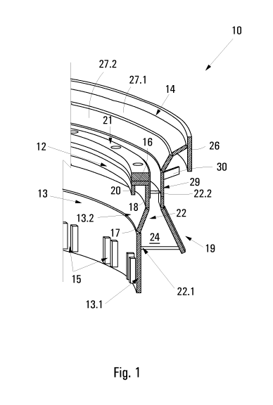
Figure 1 illustrates a radial cross-section through a rotatable throat or port
ring of a
pulveriser mill in accordance with the invention;
Figure 2 illustrates part of the rotatable throat illustrated in figure 1,
viewed radially,
in which an outer ring has been omitted for the sake of clarity;
Figure 3 illustrates a three-dimensional view of a vane forming part of the
throat
illustrated in figures 1 and 2;
Figure 4 shows a radially outer side view of the vane of figure 3;
Figure 5 illustrates a radial view of part of a further embodiment of a
rotatable
throat in which an outer ring has been omitted for clarity;
Figure 6 illustrates a three-dimensional view of the throat shown in figure 5;
Figure 7 illustrates a radial view of part of a further embodiment of a
rotatable
throat in which an outer ring has been omitted for clarity;
CA 02932143 2016-05-30
WO 2015/087286
PCT/1B2014/066834
Figure 8 shows a three-dimensional view of a vane forming part of the throat
of
figure 7;
Figure 9 shows a radial outer side view of the vane of figure 8; and
Figure 10 illustrates a radial view of part of a yet another embodiment of a
5 rotatable throat in accordance with the invention in which the outer ring
has once again
been omitted for the sake of clarity.
DETAILED DESCRIPTION OF AN EXAMPLE EMBODIMENT
The operation of vertical pulveriser mills is well known to those skilled in
the art and will
therefore not be expounded upon in the description that follows. In figures 1
and 2,
reference numeral 10 refers generally to a first embodiment of a rotatable
throat, or port
ring, which forms part of a pulveriser mill in accordance with the invention.
In order to
simplify installation, the throat or port ring 10 comprises a plurality of
segments which
are mounted around a periphery of a rotary grinding ring (not shown) of the
pulveriser
mill for rotation therewith about a rotation axis. The throat 10 is provided
in an air port or
passage which is defined by a radially outer periphery of the grinding ring
and an inner
wall of a housing of the mill. As the throat 10 rotates about the axis, air
flows from below
the grinding ring to above the grinding ring through openings provided in the
throat 10
and sweeps crushed particulate material (fines) upward to a classifier in
which the
particulate material is classified according to size.
The throat 10 comprises a rotor 12 which includes a plurality of segments (not
illustrated) which are attached to the grinding ring for rotation therewith
and are
interconnected at angularly spaced positions around the periphery of the
grinding ring.
The throat 10 further includes a stator 14 which is attached to the inner wall
of the
housing of the pulveriser mill.
The rotor 12 comprises an inner ring 13 which includes a plurality of
angularly spaced
apart mounting formations 15 for attaching the inner ring 13 to the grinding
ring of the
mill. The inner ring 13 comprises an annular, upright lower section 13.1 and a
partially
outwardly and upwardly slanted upper section 13.2. The upper section 13.2
comprises a
frusto-conical panel 17 which is connected to the upright lower section 13.1
below, an
upright panel 18 which is connected to the frusto-conical panel 17 below, a
horizontal
CA 02932143 2016-05-30
WO 2015/087286
PCT/1B2014/066834
6
disc 16, a radially outer edge of which is connected to an upper edge of the
upright
panel 18 and a depending lip 20 which depends from a radially inner edge of
the
horizontal disc 16. The depending lip 20 is configured to hook around an edge
of the
grinding ring. A dam ring 21 is provided on top of the horizontal disc 16 and
overlaps
connection points of the segmented disc 16 below in order to rigidify the
inner ring 13.
The rotor 12 further includes a partially outwardly and downwardly slanted
outer ring 19
which is radially spaced from the inner ring 13. A plurality of angularly
spaced apart
vanes 22 extend between the inner ring 13 and the outer ring 19.
With reference to figure 2, as mentioned previously, air flows from below the
throat 10
upwards through openings defined between adjacent vanes 22. Accordingly, each
vane
22 has an operatively upstream end 22.1 and an operatively downstream end
22.2. In
figure 2, the direction of rotation is indicated by arrow A. Hence, the
upstream end 22.1
of each vane 22 leads and the downstream end 22.2 trails. Accordingly, each of
the
vanes 22 is inclined with respect to the vertical at an angle of between 1 to
20 ,
preferably 18 . Contrary to conventional throats, the vanes 22 of the throat
10 in
accordance with the invention have an arcuate profile when viewed radially.
Furthermore, each of the vanes 22 exhibits a non-uniform radial width in the
axial
direction (see figure 1). In other words, each vane 22 tapers from a broad
upstream end
22.1 to a narrower downstream end 22.2. The curvature of each vane 22 is such
that a
leading face 24 which extends between the ends 22.1, 22.2 is concavely curved.
In the
example embodiment illustrated, the vanes are regularly spaced apart. Inner
and outer
side edges of each vane 22 match the profiles of the inner and outer rings 13,
19
respectively. It is to be appreciated that a cross-sectional profile of the
inner ring 13 may
vary from the example embodiment illustrated, i.e. the profile may extend
straight up
and may be absent of the frusto-conical panel 17.
Referring now to figure 4, a straight line projection L drawn from the
upstream end 22.1
of the vane 22 when viewed radially forms a first angle 13 with respect to the
vertical.
Depending on the installation, 13 may range from 10 to 80 inclusive. The
correct angle
of 13 is calculated based on the relationship of air velocity over the vane
inlet (upstream
end) and the rotational velocity of the grinding ring. Moreover, a straight
line projection T
drawn from the downstream end 22.2 forms a second angle a with respect to the
CA 02932143 2016-05-30
WO 2015/087286
PCT/1B2014/066834
7
vertical which is smaller than the first angle 13. The second angle a may
range from 10 to
200 inclusive. Again, the correct angle of a is calculated based on the
relationship of air
velocity at the vane exit (downstream end) and the rotational velocity of the
grinding
ring. Accordingly, the straight line projections L, T of the ends 22.1, 22.2
are staggered
with respect to one another.
Referring back to figure 1, the stator 14 includes a wall ring 26 which is
operatively
attached to the inner wall of the housing of the mill. The wall ring 26 has a
plurality of
holes whereby the ring 26 is attached to the wall using suitable fasteners.
The stator 14
further includes a first frusto-conical ledge cover 27.1 which extends
downwardly and
inwardly from the wall ring 26. Attached to the first ledge cover 27.1 is a
second frusto-
conical ledge cover 27.2 which extends downwardly and inwardly at a steeper
angle
than the first ledge cover 27.1, the ledge covers 27 collectively having a
rectilinear
profile when seen in cross-section. An annular panel 29 depends from a lower
edge of
the second conical ledge cover 27.2 such that it is in register with an upper
edge of the
outer ring 19 of the rotor 12 and defines a small annular gap therebetween.
The stator
14 further includes a plurality of gussets or brackets 30 which extend between
the inner
wall and the annular panel 29 thereby providing stability and support to the
stator 14.
In a known configuration, a conical ledge cover of the stator 14 has a linear
cross-
sectional profile. The Applicant has established that by altering the profile
of the ledge
cover to that illustrated in figure 1, a reduction in pressure drop at an
outlet or
downstream portion of the throat 10 can be achieved. In addition, there is a
reduction in
turbulence experienced at the outlet which means components are subjected to
less
wear and therefore have a longer life.
The invention extends to a further embodiment of a rotatable throat, reference
numeral
100 referring generally to this further embodiment of the throat in figures 5
and 6. The
same reference numerals used above have again been used below to refer to
similar
features of the throat 100.
The throat 100 includes a rotor 120 which comprises an inner ring 13 and a
plurality of
vanes 220 which are angularly spaced apart about an outer periphery of the
inner ring
13. Each vane 220 has a triangular profile when viewed radially and has an
operatively
CA 02932143 2016-05-30
WO 2015/087286
PCT/1B2014/066834
8
upstream end 220.1 and an operatively downstream end 220.2. Furthermore, each
vane 220 comprises a leading member 221, a trailing member 222, diverging from
the
leading member 221 in a downstream direction from the upstream end 220.1 and a
third
downstream member 223 which extends circumferentially between the leading
member
221 and the trailing member 222. The leading member 221 is a vane 22 as
described
above and accordingly has a leading face 24 and an arcuately curved profile
when
viewed radially. In similar fashion to the vanes 22 described above, the vanes
220 have
a non-uniform radial width in the axial direction and taper radially from
their upstream
end 220.1 to their downstream end 220.2. The third downstream member 223
serves to
blank or block a portion of the air port. This allows the vanes 220 to have a
greater
radial width without this significantly increasing the overall size of the air
port or
openings provided between the vanes 220. The size and distribution of the
third
downstream members 223 is such that they collectively cover less than 180 of
the 360
degree extent of the air port or less than 50% of the circumferential area of
the throat.
Referring now to figure 6, the rotatable throat 100 further defines a
plurality of openings
230 between the vanes 220, inner ring 13 and outer ring 19. As a result, an
upstream
inlet opening 230.1 is defined in part by the upstream ends 220.1 of adjacent
vanes 220
and a downstream outlet opening 230.2 is defined in part by downstream ends
220.2 of
adjacent vanes 220 such that the openings 230 between adjacent vanes 220
progressively decrease in cross-sectional area from the inlet 230.1 to the
outlet 230.2.
A further embodiment of a rotatable throat or port ring is designated by
reference
numeral 300 in figure 7. The throat 300 includes a plurality of regularly
spaced apart
curved or serpentine vanes 320 which are connected to the inner ring 13,
openings
being defined between adjacent vanes 320. A leading surface 324 extends
between an
upstream end 321 and a downstream end 322 of each vane 320. The leading
surface
324 exhibits a slight S-shaped curvature which is predominantly convexly
curved toward
the upstream end 321 and has a marginal concave curvature toward the
downstream
end 322 (see figure 9).
Yet another embodiment of a rotatable throat or port ring in accordance with
the
invention is designated by reference numeral 400 in figure 10. The throat 400
includes a
plurality of angularly spaced apart composite vanes 420, each of which
comprises a
CA 02932143 2016-05-30
WO 2015/087286
PCT/1B2014/066834
9
leading member 421, a trailing member 422 and a third downstream member 423.
The
trailing member 422 diverges from an upstream end of the vane 420 in a
downstream
direction in similar fashion to the trailing member 222 of the vane 220 of the
throat 100.
The downstream member 423 extends circumferentially between the leading member
421 and the trailing member 422, joining the members 421, 422 together. The
leading
member 421 is in the form of the vane 320 illustrated in figures 8 and 9.
The throats 10, 100, 300, 400 in accordance with the invention aim to improve
mill
performance by optimising air flow through the throats. Air flow velocity
through a throat
is dependent upon the rotational speed of the grinding ring of the mill and
the average
air flow velocity at the inlet of the throat. In a known rotatable throat
configuration,
planar vanes are angled at 60 relative to the horizontal irrespective of the
angular
velocity of the grinding ring and the air velocity incident upon the throat.
Consequently,
a vortex forms above the throat which hampers throughput and increases
turbulence
and component wear. Ideally, a vertical air flow pattern without any swirl is
required
above the throat in order to optimise performance. It is to be appreciated
that air
passing through the throat 10, 100 accelerates from the inlet 230.1 to the
outlet 230.2.
For this reason, the leading face 24 is arcuately curved to account for the
change in air
velocity across the vanes 22, 220 in order to ensure a vertical resultant air
flow at the
outlet 230.2. As a result of the slower air flow rate at the upstream end
22.1, 220.1, the
first angle 13 at the inlet is greater than the second angle a at the outlet
which gives rise
to the arcuate profile of the vane 22, 220 (see figure 4). Furthermore, the
widened
upstream end 22.1, 220.1 of the vanes 22, 220 provides for a gradual
acceleration
through the throat 10, 100 which reduces pressure shock. In the above example
embodiment, the number of vanes has been reduced from 64, in previous
configurations, to 50 which also contribute to a reduction in pressure drop
across the
mill. The Applicant believes that a mill including any one of the rotatable
throats 10, 100,
300, 400 as described above will enjoy improved performance due to a reduction
in
pressure drop across the mill.
In the event that flow incident upon the inlet of the throat has a strong flow
component in
the same direction as rotation of the rotary grinding member, i.e. in the same
direction
(A) as rotation of the vanes, then the design of the throats 300, 400
illustrated in figures
7 to 10 is preferred. The convexly curved portion of the leading surface 324
toward the
CA 02932143 2016-05-30
WO 2015/087286
PCT/1B2014/066834
upstream end 321 of the vane 320 helps to lead the flow into and through the
throat
300, 400 without excessive turbulence. An angle of the upstream end 321 of the
vane
320 relative to the horizontal may be determined based upon flow conditions at
the inlet
and may vary between 200 and 700 relative to the horizontal.
5