Note: Descriptions are shown in the official language in which they were submitted.
CONVERTIBLE ARM CORD LOOP HANDLE
Background of the Disclosure
Field of the Disclosure
This disclosure generally relates to resistance based exercise equipment and
more particularly to an arm cord handle for attaching a user's foot to an arm
cord
connected to a spring biased resistance exercise apparatus such as a reformer
exercise apparatus utilized to perform various Pilates exercises.
Description of Related Art
Today, many types of exercise devices are available and used for fitness
and/or medical reasons to burn off undesired calories, to improve
cardiovascular
ability, to tone or strengthen muscles, or to improve flexibility, balance,
posture, etc.
No matter what the desired end goal of a user of exercise equipment may be,
almost
all types of exercise equipment aid the user to achieve his or her desired
goal by
exerting some form of adequate and effective resistance against repeated
bodily
movements of the user.
A reformer is one such exercise device originally developed by Joseph
Pilates. A reformer is basically a rectangular frame that sits on a floor and
constitutes or carries a pair of stationary parallel rails or tracks. A
movable carriage
for supporting a user's body is mounted on the rails for movement toward and
away
from one end, the foot end, of the frame. The carriage is typically
elastically biased
toward the foot end of the frame by one or more coil springs having one end
attached to the carriage and the other to a hook or post on an anchor bar near
the
foot end of the frame.
A pair of arm cords or ropes 8 that can be grasped by a user are attached at
one end to the carriage. Each cord runs through a pulley generally located at
the
head end of the reformer. The free end of each arm cord typically has a handle
or
loop removably fastened thereto for the user to grasp with his or her hand.
This
1
CA 2932281 2018-04-27
handle is typically a single closed loop of fabric or leather, or
alternatively may be a
nested set of two loops, one larger one for large hands and an inner loop for
those
users with small hands.
Such loops are easily grasped in a user's hand. A user may also perform
exercises wherein the user's foot engages the loop. However, during such use a
user's foot can slip out of the loop because the user cannot easily grasp the
loop
itself.
To address this issue, Y-loop handles were developed that can be swapped
for the regular hand loops or hard handles. These Y-loop handles are designed
to fit
a user's foot with one leg of the Y-loop around the user's instep or forefoot
and the
other leg of the Y-loop behind the user's heel, i.e., around the user's ankle,
so as to
maintain a more secure connection between the arm cord and the user's foot. A
conventional Y-loop handle 10 is shown positioned properly on a user's leg 12
in
FIG. 1 and a pair of Y-loop handles 10 is shown separately in FIG. 2.
A disadvantage with the Y-loop handles 10 is that they are separate handles
and must be swapped out for the normally used single or double hand loops in
order
to be used. Furthermore, when the Y-loop handles 10 grasped by a user's hand,
the
extra loop is jutting out to the side and presents at least a distraction to
the user.
Summary of the Disclosure
An arm cord handle in accordance with the present disclosure includes a
flexible single or double loop handle having a U shaped distal end and has
proximal
ends joined together at a common base portion. An external strap is sewn
around
and lies against the U shaped distal end in a storage position. This external
strap
has its ends fastened to the loop handle at a location spaced from the common
base
portion. The external strap can be folded out and deployed to an operational
position
away from the U shaped distal end of the flexible loop handle. The user simply
places the strap around his or her ankle while the U shaped distal end is
positioned
2
CA 2932281 2018-04-27
around the user's forefoot.
The common base portion is preferably configured to be fastened to one end
of an arm cord that is removably and adjustably attached to one corner of a
carriage
of a reformer exercise apparatus. This flexible loop handle and the external
strap are
made preferably of a cotton webbing material. The arm cord handle preferably
further has an inner loop handle nested within the flexible loop handle. The
inner
loop handle has proximal ends fastened to the common base portion. The
external
strap is fastened to the flexible loop handle at a location adjacent a distal
end of the
inner loop handle spaced from the common base portion.
In another aspect, the present invention provides an arm cord handle
including: a flexible loop handle having a U shaped distal end and having
proximal
ends joined together at a common base portion; and an external strap lying
parallel
to and lying against an outside surface of the U shaped distal end in a
storage
position, the external strap having its ends fastened to the loop handle at a
location
spaced from the common base portion, wherein the external strap can be
deployed
to an operational position away from the U shaped distal end of the flexible
loop
handle and positioned around a user's ankle while the U shaped distal end is
positioned around the user's forefoot.
The common base portion may be configured to be fastened to an arm cord.
The flexible loop handle and the external strap may be made of a cotton
webbing
material.
The arm cord handle may include an inner loop handle nested within the
flexible loop handle, the inner loop handle having proximal ends fastened to
the
common base portion. The external strap may be fastened to the flexible loop
handle at a location adjacent a distal end of the inner loop handle spaced
from the
common base portion.
In another aspect, the present invention provides a convertible arm cord
3
CA 2932281 2018-04-27
handle including: a flexible loop handle having a U shaped distal end and
having
proximal ends joined together at a common base portion; and an external strap
lying
parallel to and lying against an outside surface of the U shaped distal end in
a
storage position, the external strap having each of its ends fastened to the
loop
handle at locations spaced from the common base portion, wherein the arm cord
handle is converted into a foot handle by folding the external strap to a
deployed
operational position away from the U shaped distal end of the flexible loop
handle
wherein the external strap is positioned around a user's ankle while the U
shaped
distal end extends around the user's forefoot.
The common base portion may be configured to be fastened to an arm cord.
The flexible loop handle and the external strap may be made of a cotton
webbing
material.
The arm cord handle may include an inner loop handle nested within the
flexible loop handle, the inner loop handle having proximal ends fastened to
the
common base portion. The external strap may be fastened to the flexible loop
handle at a location adjacent a distal end of the inner loop handle spaced
from the
common base portion.
These and other features and benefits of the arm cord handle in accordance
with the present disclosure will become clearer from the following detailed
description when taken in conjunction with the drawings described below.
Brief Description of the Drawings
FIG. 1 is a view of a user's leg with a prior art arm cord Y loop handle
attached to the user's foot.
FIG. 2 is a separate side view of a pair of the prior art arm cord Y loop
handles shown in FIG. 1.
4
CA 2932281 2018-04-27
FIG. 3 is a perspective schematic view of a double loop arm cord handle
according to an exemplary embodiment in accordance with the present
disclosure.
FIG. 4 is a side view of the double loop arm cord handle shown in FIG. 3
positioned for use around a person's foot with the ankle strap in a storage
position.
FIG. 5 is a side view of the double loop arm cord handle shown in FIG. 4 with
the ankle strap deployed around the person's ankle.
Detailed Description
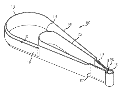
An exemplary embodiment of an arm cord handle 100 in accordance with the
present disclosure is shown in FIG. 3. This dual loop arm cord hand handle 100
has
a nested inner loop 102 and an outer loop 104 each having U shaped distal ends
116 and 112. The proximal ends of the inner and outer loops 102 and 104 are
joined
together at a common base portion 106. The base portion 106 is in turn
fastened to
a link ring 108 (shown in FIGS. 4 and 5) for fastening the handle 100 to the
free end
of an arm cord 8 (FIG. 1).
This dual loop handle 100 has an external strap 110 that extends around the
distal end 112 of the outer loop 104. Each end of the external strap 110 is
fastened
to the outer loop 104 at a location spaced from the base portion 106. This
external
strap 110, when in a storage position as shown in FIG. 3, is preferably
snuggly
abutted against the outside surface of the loop 104 such that it does not
interfere
with a user grasping the outer loop 104 with a hand in any way. Each end 114
of the
external strap 110 may preferably be fastened to the outer loop 104 at a
location
adjacent to the distal end 116 of the inner loop 102.
This dual loop handle 100 is preferably made from a single piece of fabric or
leather. One end 111 extends out from the base portion 106, forming an inner
loop
102. This piece of fabric then wraps around the base portion 106 to form a
sleeve
113 for receiving the ring 108, then back around and spaced from the inner
loop 102
CA 2932281 2018-04-27
to form the outer loop 104. The piece of fabric is then wrapped around the
sleeve
113 and its distal end 115 folded back on itself. The layers of fabric forming
the base
portion 106 adjacent the sleeve 113 are then sewn together at rectangular
stitching
117.
In order to utilize the external strap 110, it is simply folded out from or
lifted
from against and around the distal end 112 of the loop 104, and positioned
around
the user's ankle as is shown in FIG. 5. The distal end 112 of the loop 104 is
then
positioned around the user's forefoot. A separate length of a hook and loop
fastener
(e.g., VelcroTM) fabric may be utilized to secure the external strap 110 in
place
around the user's ankle. The result is a configuration on the user's leg
similar to that
shown in FIG. 1.
This embodiment 100 differs substantially from conventional y loop handles. It
adjusts to fit multiple size feet since the angle of the "Y" is not fixed.
This feature
alone enhances proprioceptive feedback. The strap 110 hides away when not in
use, and becomes part of the regular outer loop 104, as is shown in FIG. 4,
which
enables the user to avoid having to change entire loop systems to get extra
support
during an exercise.
Preferably the external strap 110 can be made from a 1 inch wide cotton
webbing sewn to the outside face of a 1.5 inch wide cotton webbing loop 104.
In this
case, the distance from the outer end 112 of the loop 104 to the distal stitch
line,
when folded flat, is preferably about 4 1/2 inches. Thus the total length of
the
external strap 110 from stitch end to stitch end is preferably about 11 inches
in this
exemplary embodiment. Other dimensions may be chosen, of course, as the above
are merely exemplary.
Various external strap materials may also be utilized such as polyester,
polypropylene or nylon TM webbing, wool, leather, vinyl, elastic, felt or
fleece
materials. The ends of the external strap 110 may be secured to the loop 104
by
sewn connection, a hook and loop fastener (e.g., VelcroTm), snap fasteners,
rivets,
6
CA 2932281 2018-04-27
grommets, or glue, although sewn stitching is currently preferred.
Furthermore, the
strap 110 could be configured to reside along the inside surface of the outer
loop
104, in which case it would be an internal strap serving the same function.
Although the embodiment 100 shown is a double loop handle configuration
the innovation here could alternatively be incorporated into a single loop
handle, in
which inner loop 102 is simply omitted. Furthermore, an additional external
strap 110
may be provided in the double loop handle configuration on the exterior of the
inner
loop 102 for those situations where the handle 100 is to be utilized by users
having
smaller legs, such as for children or smaller adults.
It will be clear that embodiments of the present disclosure are well adapted
to
attain the ends and advantages mentioned as well as those inherent therein.
While
a presently preferred embodiment has been described for purposes of this
disclosure, numerous changes may be made which will readily suggest themselves
to those skilled in the art and all such alternatives are encompassed within
the
scope of the appended claims.
7
CA 2932281 2018-04-27