Note: Descriptions are shown in the official language in which they were submitted.
CA 02932440 2016-06-01
1 '=
z
DESCRIPTION
HOLLOW FIBER MEMBRANE MODULE FOR CLEANING PLATELET
SUSPENSION
TECHNICAL FIELD
[0001]
The present invention relates to a hollow fiber membrane module for removal
of protein in a platelet suspension by washing.
BACKGROUND ART
[0002]
In production of platelet preparations, blood components collected from blood
donors are centrifuged to remove blood cell components from the blood, and the
preparations are provided as platelet suspensions in which platelets are
suspended in
blood plasma. In ordinary platelet preparations, impurities such as proteins
are
remaining in the plasma. Therefore, in transfusion of a platelet preparation,
the
proteins in the plasma may act as a cause of nonhemolytic blood transfusion
reaction.
For reducing the frequency of occurrence of such nonhemolytic blood
transfusion
reaction, it has been recommended to use platelets washed by removing
impurities
such as proteins (washed platelets). Washed platelets are produced by
physically
2 0 separating/removing impurities such as proteins from a platelet
suspension.
Examples of methods for separating and removing proteins from a platelet
suspension include centrifugation method and membrane filtration method.
[0003]
Conventionally, centrifugation method is carried out for production of washed
2 5 platelets. In the centrifugation method, a platelet suspension as a
material is
centrifuged, and the resulting supernatant, which contains proteins, is
removed,
followed by adding a preservation solution to the concentrated platelets. On
the
CA 02932440 2016-06-01
2 (
other hand, in the membrane filtration method, proteins are removed by
filtration of a
platelet suspension. For example, a plasma separation membrane module to be
used
for membrane filtration based on extracorporeal circulation has been reported
(Patent
Document 1). Specific examples of the membrane filtration reported so far
include
a method in which proteins are removed from a platelet suspension by cross-
flow
filtration, and a method in which a platelet suspension is subjected to dead-
end
filtration through a membrane (Patent Documents 2 and 3).
PRIOR ART DOCUMENTS
[Patent Documents]
[0004]
[Patent Document 1] JP 1-171566 A
[Patent Document 2] JP 2012-143554 A
[Patent Document 3] JP 2012-176081 A
SUMMARY OF THE INVENTION
PROBLEMS TO BE SOLVED BY THE INVENTION
[0005]
However, centrifugation method, which has been conventionally used for
production of washed platelets, causes serious damage to platelets, and there
are also
problems such as activation, and generation of aggregates. Moreover, since
complete removal of the supernatant is difficult, a plurality of times of
separation
needs to be carried out for sufficient reduction of the total protein amount.
Therefore, there are problems such as a laborious operation, a long processing
time
and a low platelet recovery rate.
[0006]
In the membrane filtration methods by cross-flow filtration described in
Patent Documents 1 and 2, proteins are removed by cross-flow filtration in
which a
flow parallel to a membrane and a flow filtered through the membrane are
allowed to
CA 02932440 2016-06-01
3
flow at arbitrary ratios. Therefore, proteins are not removed from the flow
parallel
to the membrane. Thus, a plurality of times of separation needs to be carried
out for
sufficient reduction of the total protein amount. Therefore, there are
problems such
as a laborious operation, a long processing time, increased platelet
activation and a
low platelet recovery rate.
[0007]
In the method described in Patent Document 3, in which a platelet suspension
is subjected to dead-end filtration through a membrane, the protein removal
rate is
high, but clogging of the membrane with platelets is likely to occur, and the
platelets
1 0 clogging the membrane are not recovered, resulting in a low platelet
recovery rate,
which is problematic. Although the document describes detachment of blood
components clogging the membrane, the filtration rate of the membrane
decreased to
not more than 20%. Therefore, the effect of suppression of clogging was
insufficient. The document does not mention the recovery rate.
[0008]
Thus, although a high protein removal rate and a high platelet recovery rate
are necessary for washing platelets by removing impurities such as proteins
from a
platelet suspension to produce washed platelets, there has not conventionally
been a
module for production of washed platelets showing both a high protein removal
rate
2 0 and a high platelet recovery rate.
[0009]
An object of the present invention is to provide a hollow fiber membrane
module for washing of a platelet suspension, which module is capable of
achieving
both a high protein removal rate and a high platelet recovery rate by
suppressing
2 5 clogging of the hollow fiber membrane with platelets.
MEANS FOR SOLVING THE PROBLEMS
[0010]
CA 02932440 2016-06-01
4'
In order to solve the problems described above, the present inventors
intensively studied to discover the following inventions (1) to (9).
(1) A hollow fiber membrane module for washing platelets by removal of
impurities from a platelet suspension, comprising:
a housing having a platelet suspension inlet, washed platelet outlet, and
filtrate outlet; and
a hollow fiber membrane for filtering the platelet suspension, wherein pores
through which the platelets do not pass, while the impurities pass, are
formed, the
hollow fiber membrane being arranged inside the housing;
wherein
the capacity of the inlet-side space which communicates with the platelet
suspension inlet and stores the platelet suspension before being filtered
through the
hollow fiber membrane in the housing is 30 to 400 mL, and the module water
permeability is 50 to 300 mL/Pa/hr.
1 5 (2) The hollow fiber membrane module according to (1), wherein the
ratio (L/A)
of the effective length (L) of the hollow fiber membrane to the cross-
sectional area
(A) of the inlet-side space vertical to the longitudinal direction of the
housing is 250
to 1300 m-1.
(3) The hollow fiber membrane module according to (1) or (2), wherein
the
2 0 maximum pressure of filtration pressure during dead-end filtration of
200 mL of a
platelet suspension containing 1.25x10⁹ platelets/mL at a flow rate of 50
mL/min is
not more than 30 kPa.
(4) The hollow fiber membrane module according to any one of (1) to (3),
wherein the ratio of pore areas on the surface of the hollow fiber membrane
facing
25 the inlet-side space is 10 to 30%.
(5) The hollow fiber membrane module according to any one of (1) to (4),
wherein the hollow fiber membrane is a membrane composed of a polysulfone-
based
CA 02932440 2016-06-01
polymer.
(6) The hollow fiber membrane module according to any one of (1) to (5),
wherein the abundance ratio of hydrophilic polylmers to the total molecules
from the
surface of the hollow fiber membrane facing the inlet-side space to a depth of
10 nm
5 is 40 to 60% by mass.
(7) The hollow fiber membrane module according to any one of (1) to (6),
wherein the abundance ratio of carbon atoms derived from ester groups to the
total
carbon atoms from the surface of the hollow fiber membrane facing the inlet-
side
space to a depth of 10 nm is 0.1 to 10 atomic percent.
(8) A platelet suspension washing device comprising:
the hollow fiber membrane module according to any one of (1) to (7); and
an air chamber which is arranged upstream of the platelet suspension inlet,
and has a capacity of 1 to 30 mL.
(9) The platelet suspension washing device according to (8), wherein a
roller
pump is arranged upstream of the air chamber along the liquid current of the
platelet
suspension.
EFFECT OF THE INVENTION
[0011]
According to the present invention, by use of a hollow fiber membrane
module having both an increased protein removal rate and an increased platelet
recovery rate, it is possible to produce washed platelets having a low total
protein
amount and a high total platelet count.
BRIEF DESCRIPTION OF THE DRAWINGS
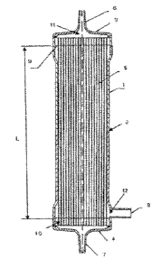
[0012]
Fig. 1 is a longitudinal cross-sectional view of a hollow fiber membrane
module for the internal pressure method according to a first embodiment of the
present invention.
CA 02932440 2016-06-01
6 f
Fig. 2 is a cross-sectional view of a hollow fiber membrane module for the
internal pressure method according to the first embodiment of the present
invention,
which cross section is vertical to the longitudinal direction of the module.
Fig. 3 is a longitudinal cross-sectional view of a hollow fiber membrane
module for the external pressure method according to a second embodiment of
the
present invention.
Fig. 4 is a cross-sectional view of a hollow fiber membrane module for the
external pressure method according to the second embodiment of the present
invention, which cross section is vertical to the longitudinal direction of
the module.
1 0 Fig. 5 is a schematic view of a platelet suspension washing device
using the
hollow fiber membrane module for the internal pressure method according to the
first
embodiment of the present invention.
MODE FOR CARRYING OUT THE INVENTION
[0013]
1 5 The hollow fiber membrane module of the present invention is a hollow
fiber
membrane module for washing platelets by removal of impurities from a platelet
suspension. The hollow fiber membrane module is characterized in that it
comprises a housing having a platelet suspension inlet, washed platelet
outlet, and
filtrate outlet; and a hollow fiber membrane for filtering the platelet
suspension,
20 wherein pores through which the platelets do not pass, while the
impurities pass, are
formed, which hollow fiber membrane is arranged inside the housing; wherein
the
capacity of the inlet-side space which communicates with the platelet
suspension
inlet and stores the platelet suspension before being filtered through the
hollow fiber
membrane in the housing is 30 to 400 mL, and the module water permeability is
50
25 to 300 mL/Paihr.
[0014]
Preferred embodiments of the present invention are described below in detail
CA 02932440 2016-06-01
71
with reference to drawings. However, the present invention is not limited to
these
embodiments. The ratios in the drawings are not necessarily the same as those
in
the description.
[0015]
As a first embodiment according to the present invention, a hollow fiber
membrane module for the internal pressure method is shown in Fig. 1 and Fig.
2.
Fig. 1 is a longitudinal cross-sectional view of the hollow fiber membrane
module for
the internal pressure method 1. Fig. 2 is a cross-sectional view of the hollow
fiber
membrane module for the internal pressure method 1, which cross section is
vertical
1 0 to the longitudinal direction of the module. In cases of a hollow fiber
membrane
module for the internal pressure method, filtration is carried out by allowing
a
platelet suspension to flow through the hollow portion of each hollow fiber
membrane.
[0016]
1 5 The hollow fiber membrane module for the internal pressure method 1
has a
constitution composed of a cylindrical member 2; a housing having headers 3
and 4
that are fluid-tightly connected and immobilized at both ends of the
cylindrical
member 2; and a bundle of hollow fiber membranes 5 stored in the housing. At
the
top portion of the header 3, a platelet suspension inlet 6 for introducing a
platelet
20 suspension into the hollow fiber membrane module, having a protruding
shape, is
formed. At the top portion of the header 4, a washed platelet outlet 7 having
a
protruding shape for releasing a liquid containing washed platelets separated
from the
platelet suspension by filtration through the bundle of the hollow fiber
membranes 5
is formed. On the lateral part in the header 4 side of the cylindrical member
2, a
2 5 filtrate outlet 8 for discharging a filtrate containing impurities such
as proteins
separated from the platelet suspension is formed.
[0017]
CA 02932440 2016-06-01
8
,
k
The bundle of the hollow fiber membranes 5 is arranged along the entire
length in the longitudinal direction in the cylindrical member 2, and both
ends of the
hollow fiber membranes 5 are immobilized in the cylindrical member 2 by a
partition
wall 9 in the header 3 side and a partition wall 10 in the header 4 side
formed with a
cured potting material such that the openings of hollow fiber membrane hollow
portions 13 as the lumens of the hollow fiber membranes 5 are not closed.
[0018]
After introduction of a platelet suspension from the platelet suspension inlet
6,
the platelet suspension flows into an inlet-side space 11. The inlet-side
space 11
herein means the space through which the platelet suspension before the
filtration
flows. In the hollow fiber membrane module for the internal pressure method 1,
the
inlet-side space 11 means the space including: the space surrounded by the
header 3
and the partition wall 9, and the space surrounded by the header 4 and the
partition
wall 10, shown in Fig. 1; and the spaces in the hollow fiber membrane hollow
1 5 portions 13, shown in Fig. 2. The inlet-side space 11 communicates with
the
platelet suspension inlet 6 and the washed platelet outlet 7. The inlet-side
space can
also be called a platelet-side space.
[0019]
The platelet suspension that flows in the inlet-side space 11 is filtered by
being passed through pores present on the surface of the hollow fiber
membranes 5,
and the filtrate containing impurities such as proteins passes the pores into
a filtrate-
side space 12. The filtrate-side space 12 means the space into which the
filtrate
containing impurities such as proteins flows after passing the pores of the
hollow
fiber membranes. In the hollow fiber membrane module for the internal pressure
2 5 method 1, the filtrate-side space 12 means the space surrounded by the
cylindrical
member 2 and the partition walls 9 and 10, excluding the hollow fiber
membranes 5
and the hollow fiber membrane hollow portions 13. The filtrate-side space 12
CA 02932440 2016-06-01
9
communicates with the filtrate outlet 8.
[0020]
As a second embodiment according to the present invention, a hollow fiber
membrane module for the external pressure method is shown in Fig. 3 and 4.
Fig. 3
is a longitudinal cross-sectional view of a hollow fiber membrane module for
the
external pressure method 14. Fig. 4 is a cross-sectional view of the hollow
fiber
membrane module for the external pressure method 14, which cross section is
vertical to the longitudinal direction of the module. In cases of a hollow
fiber
membrane module for the external pressure method, filtration is carried out by
allowing a platelet suspension to flow through the space outside the hollow
fiber
membranes. For the hollow fiber membrane module for the external pressure
method as the second embodiment, the same numbers are given to members having
the same functions.
[0021]
The hollow fiber membrane module for the external pressure method 14 has a
constitution composed of a cylindrical member 2; a housing having headers 3
and 4
that are fluid-tightly connected and immobilized at both ends of the
cylindrical
member 2; and a bundle of hollow fiber membranes 5 stored in the housing. On
the
lateral part in the header 3 side of the cylindrical member 2, a platelet
suspension
inlet 6 for introducing a platelet suspension into the hollow fiber membrane
module
is formed. On the lateral part in the header 4 side of the cylindrical member
2,
washed platelets outlet 7 having a protruding shape for releasing a liquid
containing
washed platelets separated from the platelet suspension by filtration through
the
bundle of the hollow fiber membranes 5 is formed. At the top portion of the
header
4, a filtrate outlet 8 for discharging a filtrate containing unnecessary
proteins
separated from the platelet suspension is formed.
[0022]
CA 02932440 2016-06-01
10' =
The bundle of the hollow fiber membranes 5 is arranged along the entire
length in the longitudinal direction of the cylindrical member 2, and both
ends of the
hollow fiber membranes 5 are immobilized in the cylindrical member 2 by a
partition
wall 9 in the header 3 side and a partition wall 10 in the header 4 side
formed with a
cured potting material such that the openings of the hollow fiber membrane
hollow
portions 13 as the lumens of the hollow fiber membranes 5 are not closed.
[0023]
In the first embodiment, the ends of the hollow fiber membranes 5 in the side
more distant from the filtrate outlet 8 are open. In contrast, in the hollow
fiber
1 0 membrane module for the external pressure method, the ends of the
hollow fiber
membranes 5 in the side more distant from the filtrate outlet 8 may be closed,
or may
be folded into the U-shape.
[0024]
After introduction of a platelet suspension from the platelet suspension inlet
6,
1 5 the platelet suspension flows into an inlet-side space 11. The inlet-
side space 11
herein means the space in which the platelet suspension before the filtration
is
retained. In the hollow fiber membrane module for the external pressure method
14,
the inlet-side space 11 means the space surrounded by the cylindrical member 2
and
the partition walls 9 and 10, excluding the hollow fiber membranes 5 and the
hollow
20 fiber membrane hollow portions 13. The inlet-side space 11 communicates
with the
platelet suspension inlet 6 and the washed platelet outlet 7.
[0025]
In the hollow fiber membrane module for the external pressure method 14, the
filtrate-side space 12 means the space including: the space surrounded by the
header
2 5 3 and the partition wall 9, and the space surrounded by the header 4
and the partition
wall 10; and the spaces in the hollow fiber membrane hollow portions 13. The
filtrate-side space 12 communicates with the filtrate outlet 8.
CA 02932440 2016-06-01
11'
[0026]
A platelet suspension washing device using a hollow fiber membrane module
of the present invention is shown using Fig. 5. Fig. 5 is a schematic view of
a
platelet suspension washing device using the hollow fiber membrane module for
the
internal pressure method according to the first embodiment of the present
invention.
A bag for storing a platelet suspension and a bag for storing a preservation
solution
are arranged in parallel in the most upstream of a circuit connected to the
platelet
suspension inlet 6, and tube clamps 17 are arranged downstream thereof such
that the
connection to the circuit can be switched. Between the platelet
1 0 suspension/preservation solution and the hollow fiber membrane module
for the
internal pressure method 1, a pump 16 for feeding the platelet suspension and
the
preservation solution, and an air chamber 15 for preventing inclusion of gas
into the
hollow fiber membrane module for the internal pressure method 1, are arranged.
A
bag for storing the filtrate is arranged downstream of a circuit connected to
the
filtrate outlet 8, and a bag for storing washed platelets is arranged
downstream of a
circuit connected to the washed platelet outlet 7. A tube clamp 17 is arranged
upstream of each bag such that the connection to the circuit can be switched.
[0027]
Here, the platelet suspension means a liquid prepared by removing blood cell
components from blood and separating/collecting platelets and plasma. The
platelet
suspension may contain an anticoagulant such as citric acid, and/or a
preservation
solution.
[0028]
Here, the preservation solution means a liquid for stably suspending platelets
2 5 therein. As the preservation solution, a liquid containing bicarbonate
is preferably
used.
[0029]
CA 02932440 2016-06-01
12
Here, the washing liquid means a liquid for stably washing platelets.
Similarly to the preservation solution, as the washing liquid, a liquid
containing
bicarbonate is preferably used for stable washing.
[0030]
The method for producing washed platelets from a platelet suspension using
the hollow fiber membrane module of the present invention is not limited, and
specific examples of the method for producing washed platelets include the
following.
[0031]
A method for producing washed platelets from a platelet suspension
comprises: a filtration step of subjecting a platelet suspension to dead-end
filtration
from the inlet-side space to the filtrate-side space of the hollow fiber
membrane
module, to allow a filtrate containing impurities such as proteins to pass
into the
filtrate-side space, thereby separating a liquid containing platelets from the
filtrate
containing impurities such as proteins; a washing step of allowing a washing
liquid to
1 5 flow from the inlet-side space to the filtrate-side space, to allow
impurities such as
proteins remaining in the liquid containing platelets to pass into the
filtrate-side space,
thereby removing the impurities such as proteins; and a recovering step of
recovering
a liquid containing washed platelets by allowing a preservation solution to
flow
through the inlet-side space.
[0032]
In the filtration step, the platelet suspension is introduced from the
platelet
suspension inlet of the hollow fiber membrane module, and dead-end filtration
is
carried out from the inlet-side space toward the filtrate-side space. The
filtrate
containing impurities such as proteins in the platelet suspension passes the
hollow
2 5 fiber membranes, and flows into the filtrate-side space, followed by
being discharged
from the communicating filtrate outlet. On the other hand, platelets in the
platelet
suspension cannot pass the hollow fiber membranes, and remain in the inlet-
side
CA 02932440 2016-06-01
space.
[0033]
In the washing step, the washing liquid is similarly subjected to dead-end
filtration, wherein impurities such as proteins remaining in the inlet-side
space pass
the hollow fiber membranes, and flow into the filtrate-side space, followed by
being
discharged from the communicating filtrate outlet as a filtrate containing
impurities
such as proteins.
[0034]
Thereafter, in the recovering step, the preservation solution is introduced
from
1 0 the platelet suspension inlet into the inlet-side space to mix the
platelets with the
preservation solution, and the resulting mixture is released from the washed
platelet
outlet as a liquid containing platelets. In this process, in cases where the
volume of
the platelet suspension used as the material is the same as the volume of the
preservation solution, washed platelets having the same platelet concentration
as that
before the treatment can be obtained.
[0035]
Since, by reducing the capacity of the inlet-side space, the volume of the
liquid filtered in the filtration step can be increased, the amount of
impurities such as
proteins remaining in the inlet-side space can be reduced. Moreover, since the
volume of the platelet suspension in the inlet-side space can be decreased in
the
washing step, the washing efficiency can be increased, and the removal rate of
impurities such as proteins can be increased even with a small volume of the
washing
liquid. In the recovering step, since the volume of the preservation solution
used for
the recovery relative to the liquid volume in the inlet-side space decreases,
the
2 5 recovery rate of platelets decreases. On the other hand, in cases where
the capacity
of the inlet-side space is too small, the concentration of platelets remaining
in the
inlet-side space is high in the filtration step, so that activation and
aggregation of
CA 02932440 2016-06-01
14! =
platelets are more likely to occur due to interactions between platelets.
Thus, the
capacity of the inlet-side space of the hollow fiber membrane module needs to
be not
less than 30 mL, and is preferably not less than 70 mL. The capacity needs to
be not
more than 400 mL, and is preferably not more than 200 mL.
[0036]
In conventional hollow fiber membrane modules, during filtration of a platelet
suspension by dead-end filtration, the filtration pressure increases due to
clogging of
the surfaces of the hollow fiber membranes with platelets. Due to the increase
in
the filtration pressure, the platelets are strongly pushed against the
membranes, and
1 0 this causes aggregation of the platelets, leading to further progress
of the clogging.
When aggregation of the platelets occurs, the platelets adhere to the surfaces
of the
hollow fiber membranes. In such cases, the platelets cannot be detached by the
flow
of the preservation solution for recovery of platelets, and remain on the
surfaces of
the hollow fiber membranes, resulting in a decrease in the platelet recovery
rate.
1 5 Moreover, in cases where filtration is carried out by the internal
pressure method, in
which a platelet suspension is allowed to flow through the hollow fiber
membrane
hollow portions, aggregated platelets cause occlusion of the hollow portions.
In
these cases, the platelet recovery rate is low since, even if the preservation
solution is
allowed to flow for recovery of platelets, the preservation solution cannot
easily pass
20 through hollow fiber membrane hollow portions. In particular, since
platelet
suspensions used for blood transfusion often have 3-fold or higher
concentrations of
platelets than the platelet concentration in the body, they are more likely to
cause
clogging during the filtration.
[0037]
2 5 In order to suppress clogging and to increase the platelet recovery
rate in
filtration of a platelet suspension by dead-end filtration, it is necessary to
maintain a
state where the filtration pressure is low, and platelet aggregation is
suppressed. In
CA 02932440 2016-08-25
76199-453
cases where the water permeability of the hollow fiber membrane module is low,
the
filtration pressure is high, so that the platelet recovery rate is low.
[0038]
The water permeability of a hollow fiber membrane module depends on the
5 water permeability and the membrane area of the hollow fiber membranes
contained
therein. Therefore, an increase in the water permeability is accompanied by an
increase(s) in the membrane area and/or the water permeability of the hollow
fiber
membranes. However, in cases where the membrane area of the hollow fiber
membranes is increased, the size of the hollow fiber membrane module
increases,
10 causing problems such as difficulty in handling and an increase in the
volume of the
liquid for washing before the use of the hollow fiber membrane module. In
general,
for the purpose of increasing the water permeability of a hollow fiber
membrane, the
pore size of the hollow fiber membrane is increased. However, in cases where
the
pore size is increased, platelets are more likely to penetrate the membrane.
15 [0039]
In view of this, the present inventors carried out experiments, and, as a
result,
found optimal water permeability of the hollow fiber membrane with which the
platelet recovery rate can be increased while ease of handling of the hollow
fiber
membrane module is maintained. More specifically, the water permeability of
the
hollow fiber membrane needs to be not less than 2.5 mL/Paihr/m2, and is
preferably not
less than 4 mL/Pa/hr/m2. The water permeability of the hollow fiber membrane
needs
to be not more than 15 mL/Pa/hr/m2, and is preferably not more than 13
mL/Pa/hr/m2.
[0040] =
As a result of experiments, it was found that the ratio of pore areas on the
surfaces of the hollow fiber membranes in the inlet-side space is preferably
increased
for suppression of the increase in the filtration pressure due to clogging.
More
specifically, the ratio of pore areas on the surfaces of the hollow fiber
membranes in
CA 02932440 2016-08-25
76199-453
16
the inlet-side space is preferably not less than 10%, more preferably not less
than
12%. On the other hand, in cases where the ratio of pore areas is too high,
the
strength of the membrane is insufficient, so that the ratio of pore areas is
preferably
not more than 30%, more preferably not more than 20%. The ratio of pore areas
means the ratio of the total area of the pores on the surfaces of the hollow
fiber
membranes to the area of the surfaces of the hollow fiber membranes. The
method
for measuring the ratio of pore areas is described later in detail. The ratio
of pore
-areas can be obtained by subjecting an image taken with an electron
microscope at a
magnification of x1000 to image processing using known software such as Matrox
1 0 Inspector 2.2 (Matrox Electronic Systems Ltd.).
[0041]
From the viewpoint of increasing the platelet recovery rate while suppressing
the platelet aggregation, the filtration pressure in the filtration step is
preferably not
more than 30 kPa. As the material of washed platelets, 5, 10, 15, or 20 units
of a
1 5 platelet suspension is commonly used. In particular, IO units of a
platelet
suspension is most frequently used. In this standard, 10 units of a platelet
suspension means that the platelet concentration is 8.3 x 10⁸ platelets/mL to
1.8x10⁹
platelets/mL, and that the liquid volume is 160 mL to 240 mL. In the hollow
fiber
membrane module of the present invention, the maximum pressure of filtration
2 0 pressure during dead-end filtration of 200 mL of a platelet suspension
containing
1.25x le platelets/mL, which is 10 units of a platelet preparation, at a flow
rate of 50
mL/min is preferably not more than 30 kPa, more preferably not more than 20
kPa.
[0042]
In the filtration step, a shear stress is applied to the platelets due to
contact of
2 5 the platelets with the surfaces of the hollow fiber membranes in the
feeding space
side. It is known that application of a high shear stress to platelets causes
activation
of the platelets. Therefore, by reducing the shear stress applied to the
platelets in
CA 02932440 2016-06-01
17
the filtration step, aggregation of the platelets can be suppressed, and the
platelet
recovery rate can be increased. On the other hand, in the recovering step, the
shear
stress applied to the platelets is increased to allow easier detachment of
platelets
adhered to the surfaces of the hollow fiber membranes. This increases the
platelet
recovery rate. The shear stress applied to the platelets is proportional to
the linear
velocity of the flow in the hollow fiber membrane module.
[0043]
As the ratio (L/A) of the effective length (L) of the hollow fiber membrane to
the cross-sectional area (A) of the inlet-side space vertical to the
longitudinal
1 0 direction of the housing increases, the linear velocity increases. As
L/A decreases,
the linear velocity decreases. For example, in cases where the flow rate is
within
the range of 50 mL/min. to 500 mL/min., L/A is preferably not less than 250 m-
1,
more preferably not less than 500 m-1, from the viewpoint of increasing the
linear
velocity for detaching platelets adhered to the hollow fiber membranes to
increase the
platelet recovery rate. On the other hand, L/A is preferably not more than
1300 m-1,
more preferably not more than 700m-1, from the viewpoint of decreasing the
linear
velocity for suppressing platelet aggregation to increase the platelet
recovery rate.
[0044]
The effective length of a hollow fiber membrane means the length of the
hollow fiber membrane in which filtration is substantially possible, and
corresponds
to the length of the hollow fiber membrane excluding the partition walls and
the
portions embedded in the partition walls. The membrane area of the hollow
fiber
membrane module is calculated using this effective length as a standard.
[0045]
2 5 In a hollow fiber membrane module for the internal pressure method,
the
cross-sectional area (A) of the inlet-side space vertical to the longitudinal
direction of
the housing is the cross-sectional area of the hollow fiber membrane hollow
portions,
CA 02932440 2016-06-01
18
and calculated according to Equation 1.
[0046]
A = (ID / 2)2 x x n ... Equation 1
A: Cross-sectional area of the inlet-side space vertical to the
longitudinal direction of the housing (m2)
ID: Hollow fiber inner diameter (m)
a: Circumference ratio
n: Number of hollow fiber membranes
[0047]
Here, in cases where the hollow fiber membranes contained in the hollow
fiber membrane module are composed of two or more kinds of hollow fiber
membranes having different hollow fiber inner diameters, Equation 1 is applied
to
each kind of hollow fiber membranes, and the obtained values are integrated to
calculate the cross-sectional area (A) of the inlet-side space vertical to the
1 5 longitudinal direction of the housing.
[0048]
In a hollow fiber membrane module for the external pressure method, the
cross-sectional area (A) of the inlet-side space vertical to the longitudinal
direction of
the housing is a value obtained by subtracting the cross-sectional area of the
hollow
fiber membranes from the cross-sectional area of the housing at a position
where the
platelet suspension inlet and the washed platelet outlet are absent, and
calculated
according to Equation 2 and Equation 3.
[0049]
Am = (OD / 2)2 x xn ... Equation 2
A = AH - Am ... Equation 3
A: Cross-sectional area of the inlet-side space vertical to the
longitudinal direction of the housing (m2)
CA 02932440 2016-08-25
76199-453
19
AH: Cross-sectional area of the housing (m2)
Am: Cross-sectional area of the hollow fiber membranes (m2)
OD: Hollow fiber outer diameter (m)
n: Circumference ratio
n: Number of hollow fiber membranes
[0050]
Here, in cases where the hollow fiber membranes contained in the hollow
fiber membrane module are composed of two or more kinds of hollow fiber
membranes having different hollow fiber outer diameters, Equation 2 is applied
to
1 0 each kind of hollow fiber membranes, and the obtained values are
integrated to
calculate the cross-sectional area of the hollow fiber membranes (Am). The
cross-
sectional area of the housing is the mean calculated for the same section as
that for
the effective length of the hollow fiber membrane in the longitudinal
direction of the
housing. For example, in cases where the housing has a shape which
continuously
1 5 changes in the longitudinal direction, the cross-sectional area is
measured at each of a
total of five points positioned at the same intervals from one end to the
other end of
the section which is the same as that for the effective length of the hollow
fiber
membrane in the longitudinal direction, and the arithmetic mean of the
measured
values is calculated. In cases where the housing has a shape which
discontinuously
2 0 changes in the longitudinal direction, the cross-sectional area is
measured in each of
portions having different shapes, and each measured value is multiplied by the
ratio
of the corresponding portion in the section which is the same as that for the
effective
length of the hollow fiber membrane in the longitudinal direction, followed by
calculating the sum of the obtained values to determine the mean of the cross-
2 5 sectional area of the housing.
[0051]
In the present invention, the hollow fiber membranes used for the hollow fiber
CA 02932440 2016-06-01
20 .
membrane module are not limited as long as they are hollow fiber membranes
produced using a material which suppresses platelet activation, that is, a
material
having blood compatibility. Hollow fiber membranes used in known methods for
producing washed platelets by membrane filtration, for example, the hollow
fiber
membranes described in Patent Documents 2 and 3, may be preferably used.
[0052]
Specific examples of the material of the hollow fiber membranes include, but
are not limited to, polysulfone-based polymers, polystyrene, polyurethane,
polyethylene, polypropylene, polycarbonate, polyvinylidene fluoride, and
1 0 polyacrylonitrile. In particular, hollow fiber membranes produced
using, as a main
material, the so-called polysulfone-based polymer such as polysulfone or
polyethersulfone are known to have excellent water permeability and
fractionation
performance. In the present invention, a polysulfone-based polymer is
preferably
used as the material. The polysulfone-based polymer means a polymer having an
aromatic ring, sulfonyl group, and ether group in its backbone.
[0053]
Examples of the polysulfone-based polymer include polysulfones represented
by General Formula (I), polysulfones represented by General Formula (II),
polyethersulfones, and polyallylethersulfones. Among these, polysulfones
represented by General Formula (I), and polysulfones represented by General
Formula (II), are preferred. The number n is more preferably 50 to 80. A block
copolymer of a polysulfone represented by General Formula (I) or (II) and
other
monomers, or a modified body of a polysulfone represented by General Formula
(I)
or (II), may be used. The ratio of the polysulfone-derived structure in the
block
2 5 copolymer of a polysulfone represented by General Formula (I) or (II)
and other
monomers is preferably not less than 90% by mass with respect to the entire
block
copolymer.
CA 02932440 2016-06-01
21
[0054]
=
CH 3
el 0-L)-- Sil -0- 0- = = = ( I )
I
CH 3 O11
- o- = = = (1 1)
I
0 n
[0055]
The inner diameter and the membrane thickness of the hollow fiber
membranes are not limited. Hollow fiber membranes having an inner diameter of
about 100 to 500 gm and a membrane thickness of about 30 to 200 jam may be
1 0 preferably used.
[0056]
The average pore size of the pores of the hollow fiber membranes is not
limited as long as platelets do not pass through the pores, while impurities
pass
through the pores. Since the sizes of the platelets, especially human
platelets, to be
1 5 subjected to the washing treatment are 2 to 4 tim, the average pore
size is not more
than 1.5 lam, preferably not more than 1 pm.
[0057]
Each hollow fiber membrane constituting the hollow fiber membrane bundle
preferably contains, in order to prevent activation of platelets in contact
with the
2 0 hollow fiber membrane, a hydrophilic component at least on the surface
which
contacts platelets (for example, in cases of filtration by the internal
pressure method,
at least on the lumen-side surface of the hollow fiber membrane). The
"hydrophilic
component" herein means a substance which is easily soluble in water, having a
CA 02932440 2016-06-01
22
solubility of not less than 10 g/100 g in pure water at 20 C. A hydrophilic
polymer
is preferably used as the hydrophilic component.
[0058]
By the inclusion of the hydrophilic polymer on the surface of the hollow fiber
membrane, the blood compatibility can be increased, and the platelet
aggregation can
be suppressed. From the viewpoint of suppression of the platelet aggregation,
the
abundance ratio of hydrophilic polymers to the total molecules in the portion
from
the surface of the hollow fiber membrane in the inlet-side space to a depth of
10 nm
is preferably not less than 40% by mass. On the other hand, in cases where the
1 0 hydrophilic polymer is present in an excess amount, elution of the
hydrophilic
polymer from the hollow fiber membrane may occur to cause contamination of the
washed blood product. Moreover, swelling of the hydrophilic polymer on the
surface of the hollow fiber membrane may cause narrowing of the pores of the
hollow fiber membrane, leading to a decrease in the water permeability. Thus,
the
abundance ratio of hydrophilic polymers to the total molecules in the portion
from
the surface of the hollow fiber membrane in the inlet-side space to a depth of
10 nm
is preferably not more than 60% by mass.
[0059]
The hydrophilic polymer herein means a water-soluble polymer, or a water-
2 0 insoluble polymer that interacts with water molecules by electrostatic
interaction
and/or hydrogen bonds. The hydrophilic polymer herein means a polymer that can
be dissolved at a ratio of not less than 1000 ppm in pure water at 25 C.
Specific
examples of the hydrophilic polymer include, but are not limited to,
polyalkylene
glycols such as polyethylene glycol and polypropylene glycol; nonionic
hydrophilic
2 5 polymers such as polyvinyl alcohol, polyvinyl pyrrolidone, polyvinyl
acetate,
polyvinyl caprolactam, hydroxyethyl methacrylate, and methyl methacrylate; and
ionic hydrophilic polymers such dextran sulfate, polyacrylic acid,
polyethylenimine,
CA 02932440 2016-06-01
23
and polyallylamine.
[0060]
Examples of the method for including the hydrophilic polymer on the hollow
fiber membrane surface include: coating by physical adsorption; thermal or
radiation
cross-linking; and chemical bonding by chemical reaction. In the process of
producing a hollow fiber membrane, a membrane-forming liquid is discharged
from a
double annular nozzle while an injection liquid is allowed to flow inside. The
hydrophilic polymer may be added to the injection liquid. In such a case, the
hydrophilic polymer in the injection liquid is diffused into the membrane-
forming
liquid side before the phase separation of the hollow fiber membrane occurs to
establish the membrane structure. Therefore, the hydrophilic polymer can be
localized on the hollow fiber membrane surface.
[0061]
The abundance ratio of hydrophilic polymers to the total molecules in the
portion from the surface of the hollow fiber membrane in the inlet-side space
to a
depth of 10 run can be calculated by carrying out measurement by X-ray
electron
spectroscopy (hereinafter referred to as "ESCA") at a measurement angle of 90
and
investigating the abundance ratios of elements in the portion from the surface
of the
hollow fiber membrane to a depth of 10 nm. More specifically, the abundance
ratio
of hydrophilic polymers to the total molecules can be measured and calculated
by the
following method.
[0062]
In cases of a hollow fiber membrane module for the internal pressure method,
when the measurement is carried out for the portion from the surface of the
hollow
2 5 fiber membrane in the inlet-side space to a depth of 10 nm, the inner
surface of the
hollow fiber membrane is exposed by cutting the membrane into a semi-
cylindrical
shape using a single-edged blade. After rinsing the hollow fiber membrane with
CA 02932440 2016-08-25
76199-453
24
ultrapure water, the membrane is dried at room temperature at 0.5 Torr for 10
hours
to provide a measurement sample. The sample is set in the apparatus, and the
angle
of the detector with respect to the angle of incidence of X-ray is adjusted
such that
the measurement angle becomes 900. From the integrated intensity of the
spectrum
of each of Cl s, N1 s, and S2p, and the relative sensitivity coefficient
specific to the
apparatus, the abundance ratios of carbon atoms, nitrogen atoms, and sulfur
atoms
are determined.
[0063]
Here, for example, in cases where polysulfone and a hydrophilic polymer
material polyvinyl pyrrolidone are used as materials of the hollow fiber
membrane,
the abundance ratio of polyvinyl pyrrolidone on the surface is calculated
according to
the following Equation 4.
[0064]
Abundance ratio of polyvinyl pyrrolidone on the surface (% by mass) = N x
111 / (N x 111 + S x 442) x 100 ... Equation 4
Abundance ratio of nitrogen atoms
S: Abundance ratio of sulfur atoms
111: Repeating unit molecular weight of polyvinyl pyrrolidone
442: Repeating unit molecular weight of polysulfone.
[0065]
As mechanisms of adhesion of platelets to the hollow fiber membrane surface,
there are two pathways. In the first pathway, activation of platelets
immediately
occurs when the platelets contact the hollow fiber membrane surface, and this
activation causes aggregation and adhesion of the platelets. In the second
pathway,
2 5 proteins involved in blood coagulation such as fibrinogen adhere to the
surface of the
hollow fiber membrane, and activate platelets to induce adhesion of the
platelets.
Thus, for suppression of the adhesion of platelets to the hollow fiber
membrane
CA 02932440 2016-06-01
25.
surface, it is necessary to prevent approach of platelets to the hollow fiber
membrane
surface, and adhesion of proteins such as fibrinogen to the hollow fiber
membrane
surface.
[0066]
As means for preventing approach of platelets to the hollow fiber membrane
surface, formation of a diffuse layer with a hydrophilic polymer on the hollow
fiber
membrane surface is effective. The excluded volume effect by the diffuse layer
prevents platelets from approaching the hollow fiber membrane surface. By the
formation of the diffuse layer, adhesion of proteins such as fibrinogen to the
hollow
1 0 fiber membrane surface can also be prevented. However, in cases where
the
hydrophilicity of the diffuse layer is too high, bound water in the vicinity
of proteins
is trapped in the diffuse layer, and this causes structural changes of the
proteins,
resulting in adhesion of the proteins to the hollow fiber membrane surface.
Thus,
the effect to suppress adhesion of proteins such as fibrinogen decreases. The
bound
water herein means water which is present in the vicinity of proteins and
whose
movement is restricted by hydrogen bonds. It is thought that bound water
stabilizes
the structures of proteins.
[0067]
Examples of hydrophilic polymers preferred for formation of the diffuse layer
include water-insoluble polymers having a rather hydrophobic unit, such as
vinyl
caprolactam, propylene glycol, vinyl acetate, hydroxyethyl methacrylate, and
methyl
methacrylate. Polymers having an ester group are more preferred. Polymers
having a side-chain type ester group such as a vinyl acetate group or methyl
acrylate
group are still more preferred. It is assumed that side-chain type ester
groups such
2 5 as a vinyl acetate group and methyl acrylate group do not trap bound
water since they
are moderately hydrophilic. On the other hand, highly hydrophobic polymers
such
as polyethylene terephthalate are not preferred even in cases where they have
an ester
CA 02932440 2016-06-01
26
group.
[0068]
Since homopolymers of units such as vinyl caprolactam, propylene glycol,
vinyl acetate, hydroxyethyl methacrylate, and methyl methacrylate are less
likely to
form a swelled diffuse layer, the hydrophilic polymer is preferably a
copolymer of
these units and units such as vinyl pyrrolidone, ethylene glycol, or vinyl
alcohol.
From the viewpoint of the balance between the water solubility and the
hydrophobicity, the hydrophilic polymer is more preferably a copolymer of
vinyl
pyrrolidone and vinyl acetate, copolymer of vinyl pyrrolidone and methyl
1 0 methacrylate, copolymer of ethylene glycol and vinyl acetate, or
copolymer of
ethylene glycol and methyl methacrylate.
[0069]
Hydrophilic polymers suitable for formation of the diffuse layer are
preferably
those having favorable balances between the water solubility and the
hydrophobicity
in a single molecule. The hydrophilic polymer is preferably a random copolymer
or
an alternating copolymer. In cases where the copolymer has an ester group, the
molar ratio of ester group units is preferably 0.3 to 0.7.
[0070]
The abundance ratio of carbon atoms derived from ester groups to the total
carbon atoms in the portion from the surface of the hollow fiber membrane in
the
inlet-side space to a depth of 10 nm can be calculated by carrying out
measurement
by ESCA at a measurement angle of 90 , and splitting the peak of the component
derived from ester groups from the entire Cls peak in the portion from the
hollow
fiber membrane surface to a depth of about 10 nm. More specifically, the peak
of
2 5 the component derived from ester groups is split from the entire peak
of the
following five components constituting Cls: the component mainly derived from
CHx, C-C, C=C, and C-S; the component mainly derived from C-0 and C-N; the
CA 02932440 2016-08-25
7610-453
27
component derived from 7C-7C* satellite; the component derived from C=0; and
the
component derived from ester groups. By calculating the peak area ratio of the
component derived from ester groups to the area of the entire Cls peak
(hereinafter
referred to as "ester group-derived peak area ratio"), the abundance ratio of
carbon
atoms derived from ester groups to the total carbon atoms can be calculated.
The
peak of the component derived from ester groups appears at + 4.0 to 4.2 eV
from the
main peak of the component derived from Mx and the like (near 285 eV). The
value obtained by multiplying the carbon amount of Cls (atomic percent) by the
ester
group-derived peak area ratio (the measurement is carried out at three
positions, and
1 0 the mean of the measured values (rounded to the ones place) is
calculated; in cases
where the ester group-derived peak area ratio is not more than 0.4%, the ratio
is
regarded as below the detection limit) is the abundance ratio of carbon atoms
derived
from ester groups to the total carbon atoms on the hollow fiber membrane
surface in
the inlet-side space. The abundance ratio of carbon atoms derived from ester
groups
1 5 to the total carbon atoms is preferably not less than 0.1 atomic
percent, more
preferably not less than 0.5 atomic percent. The abundance ratio of carbon
atoms
derived from ester groups is preferably not more than 10 atomic percent, more
preferably not more than 5 atomic percent, still more preferably not more than
1 atomic
percent.
20 [0071]
For retaining the hydrophilic polymer on the hollow fiber membrane surface,
it is advantageous for the hydrophilic polymer to have a large number of
crosslinking
points, that is, to have a high weight average molecular weight. However, in
cases
where the weight average molecular weight is too high, it is difficult to keep
the
2 5 membrane surface in a uniform state on the hollow fiber membrane
surface because
of its high viscosity and gelation, so that a swelled diffuse layer cannot be
formed.
On the other hand, in cases where the weight average molecular weight is 100
low,
CA 02932440 2016-06-01
28. ,
elution of the hydrophilic polymer may occur. Thus, the weight average
molecular
weight of the hydrophilic polymer is preferably 5000 to 1,500,000, more
preferably
10,000 to 1,000,000.
[0072]
The hydrophilic polymer may have a single weight average molecular weight,
or may be a mixture of a plurality of kinds of hydrophilic polymers having
different
weight average molecular weights. The hydrophilic polymer may be prepared by
purifying a commercial product such that it has a narrowed weight average
molecular
weight distribution.
[0073]
In cases where polyvinyl pyrrolidone (hereinafter described as PVP) is used as
the hydrophilic polymer, those referred to as K15 to K120 are preferred. From
the
viewpoint of increasing the hydrophilicity, the weight average molecular
weight of
the PVP is preferably not less than 10,000, more preferably not less than
40,000.
1 5 PVP is a water-soluble polymer produced by vinyl polymerization of N-
vinyl
pyrrolidone, and products having various molecular weights are commercially
available under the trade names of, for example, Luvitec (registered
trademark),
which is manufactured by BASF; Plasdone (registered trademark), which is
manufactured by ISP; and Pitzcol (registered trademark), which is manufactured
by
2 0 DKS Co. Ltd.
[0074]
Commercially available copolymers of PVP and vinyl acetate have weight
ratios of PVP:vinyl acetate of (7:3), (6:4), (5:5), (3:7), and the like. It is
preferred to
use, for example, VA64 which has a weight ratio of 6/4, VA73, VASS, VA37, or
2 5 PVC55 of Kollidon (registered trademark), manufactured by BASF.
[0075]
The method for controlling the abundance ratio of hydrophilic polymers on
CA 02932440 2016-06-01
29
the hollow fiber membrane surface in the inlet-side space is not limited, and
examples of the method include a method in which the hydrophilic polymer is
mixed
with the membrane-forming liquid in the production process of the hollow fiber
membrane, a method in which a hydrophilic-polymer solution is brought into
contact
with the surface during the membrane formation, and a method in which the
surface
is coated with the hydrophilic polymer. In these methods, after giving the
hydrophilic polymer to the surface, the hydrophilic polymer may be cross-
linked to
the hollow fiber membrane by, for example, radiation or thermal treatment. By
this,
elution of the hydrophilic polymer from the hollow fiber membrane surface can
be
1 0 suppressed. Alternatively, the hydrophilic polymer may be immobilized
on the
hollow fiber membrane by chemical reaction.
[0076]
In the thermal cross-linking, in which the obtained hollow fiber membrane is
heated, hydrophilic polymers present on the hollow fiber membrane surface are
1 5 cross-linked to each other. From the viewpoint of allowing the cross-
linking
between the hydrophilic polymers while preventing degradation reaction, the
temperature during the thermal cross-linking is preferably 120 to 250 C, more
preferably 130 to 200 C. The length of time of the thermal cross-linking is
preferably 1 to 10 hours, more preferably 3 to 8 hours.
20 [0077]
In the radiation cross-linking, in which the obtained hollow fiber membrane is
irradiated with radiation, the hydrophilic polymer is cross-linked to the
polysulfone-
based polymer. From the viewpoint of allowing the cross-linking reaction to
proceed while preventing degradation reaction, the radiation dose during the
2 5 radiation cross-linking is preferably 5 to 75 kGy, more preferably 10
to 50 kGy. As
the radiation for the irradiation, a-ray, 13-ray, X-ray, 7-ray, or electron
beam is
employed. Among these, y-ray and electron beam is preferred. For allowing the
CA 02932440 2016-06-01
30,
cross-linking reaction to proceed more easily, water is preferably added to
the hollow
fiber membrane to be subjected to the radiation cross-linking.
[0078]
In the washed platelets, platelets are suspended in a preservation solution
having high storage stability for the platelet function, instead of the blood
plasma,
which is removed during the production. In the recovering step, a preservation
solution containing bicarbonate is preferably used as the preservation
solution for
recovery of platelets in the hollow fiber membrane module. In the filtration
step or
the washing step, a preservation solution containing bicarbonate is preferably
used
since it has high affinity with platelets.
[0079]
In cases where a preservation solution containing bicarbonate is allowed to
flow into the hollow fiber membrane module, there is a problem of inclusion of
bubbles into the hollow fiber membrane module, since carbon dioxide gas is
generated from bicarbonate. If bubbles are included in the hollow fiber
membrane
module, platelet aggregation due to contact of platelets with the bubbles is
likely to
occur, leading to a low platelet recovery rate. Moreover, the bubbles block
the
channel in the inlet-side space of the hollow fiber membrane module, and
prevent the
liquid flow. As a result, the washing and the recovery become difficult,
leading to
decreases in the protein removal rate and the platelet recovery rate. By
connecting a
circuit having an air chamber upstream of the platelet suspension inlet,
introduction
of bubbles generated from the preservation solution into the hollow fiber
membrane
module can be suppressed. For sufficient removal of bubbles generated from the
preservation solution, the capacity of the air chamber is preferably not less
than 1 mL.
On the other hand, in cases where the capacity of the air chamber is small,
retention
of platelets in the chamber is suppressed, and the platelet recovery rate
increases as a
result. Thus, the capacity of the air chamber is preferably not more than 30
mL.
CA 02932440 2016-06-01
31 ,
[0080]
For carrying out dead-end filtration of a platelet suspension using a hollow
fiber membrane module, the following methods can be employed: constant
pressure
filtration, in which the platelet suspension is fed at a constant pressure;
and constant
rate filtration, in which the platelet suspension is fed at a constant rate.
Since, as
mentioned above, the linear velocity of the flow of the platelet suspension
influences
the platelet recovery rate, the dead-end filtration is preferably carried out
by constant
rate filtration, in which the flow rate can be controlled. Examples of means
for
feeding the platelet suspension at a constant rate include syringe pumps and
roller
pumps. Roller pumps are preferred since they can feed a large amount of the
platelet suspension. On the other hand, since squeezing by a roller pump is
likely to
cause generation of bubbles from the preservation solution containing
bicarbonate, it
is preferred to arrange a roller pump, air chamber, and hollow fiber membrane
module in this order from the upstream side where the platelet suspension is
fed.
[0081]
In the present invention, a hollow fiber membrane module for the internal
pressure method is especially preferably used since, in such a case,
unevenness of the
feed rate of the platelet suspension is less likely to occur; the hollow fiber
membranes
can be uniformly used; and retention of platelets can be suppressed.
EXAMPLES
[0082]
The present invention is described below in detail by way of Examples.
However, the present invention is not limited thereto.
[0083]
2 5 Measurement of Water Permeability:
The water permeability of the hollow fiber membrane module is calculated by
cutting hollow fiber membranes out from the hollow fiber membrane module, and
CA 02932440 2016-06-01
32,
measuring the water permeability per unit membrane area of the hollow fiber
membranes, followed by multiplying the measured value by the membrane area of
the hollow fiber membranes contained in the hollow fiber membrane module.
First,
the water permeability per unit membrane area can be measured by the following
method. Hollow fiber membranes contained in the hollow fiber membrane module
were cut out. The hollow fiber membranes were inserted into a plastic pipe,
and
both ends of the hollow fiber membranes were potted to the inner walls at both
ends
of the plastic pipe, to prepare a mini-module having an effective length of 10
cm.
The number of the hollow fiber membranes was adjusted such that the membrane
area of the mini-module was 0.003 m2. In cases where a hollow fiber membrane
module for the internal pressure method is used, the membrane area corresponds
to
the membrane area based on the inner diameter. In cases where a hollow fiber
membrane module for the external pressure method is used, the membrane area
corresponds to the membrane area based on the outer diameter. The membrane
area
of the mini-module was calculated according to the following Equation 5. Here,
when the hollow fiber membrane module contained two or more kinds of hollow
fiber membranes, the respective kinds of hollow fiber membranes were used such
that the ratios of their numbers were the same between the hollow fiber
membrane
module and the mini-module, and, in the calculation of the membrane area, the
values calculated for the respective kinds of hollow fiber membranes according
to
Equation 5 were integrated.
[0084]
Amin; =Dx7rxLxn ... Equation 5
Amin,: Membrane area of the mini-module (m2)
D: Hollow fiber diameter (m) (inner diameter in the internal pressure
method, or outer diameter in the external pressure method)
it: Circumference ratio
CA 02932440 2016-06-01
33,
L: Effective length (m)
n: Number of hollow fiber membranes
[0085]
To the mini-module prepared, a water pressure of 1.3 x 10⁴ Pa was applied,
and the amount of water released per unit time into the side where the
filtrate from
the hollow fiber membranes is obtained was measured. In terms of the direction
of
application of the water pressure, when the hollow fiber membrane module was
to be
used by the internal pressure method, the water pressure was applied to the
mini-
module by the internal pressure method. When the hollow fiber membrane module
1 0 was to be used by the external pressure method, the water pressure was
applied to the
mini-module by the external pressure method. According to the following
Equation
6, the water permeability of the hollow fiber membranes was calculated.
[0086]
Fm = Q / (T x p x Amin') ... Equation 6
1 5 Fm: Water permeability of the hollow fiber membranes
(mUhr/Pa/m2)
Q: Amount of water released (mL)
T: Length of time of application of the water pressure (hr)
P: Water pressure (Pa)
Amin': Membrane area of the mini-module (m2)
20 [0087]
Subsequently, the membrane area of the hollow fiber membrane module was
calculated according to Equation 7. Here, when the hollow fiber membrane
module
contained two or more kinds of hollow fiber membranes, the values calculated
for the
respective kinds of hollow fiber membranes according to Equation 7 were
integrated.
25 The water permeability of the hollow fiber membrane module was
calculated
according to the following Equation 8.
[0088]
CA 02932440 2016-06-01
34
Amp = D x 7c xLxn ... Equation 7
Amp: Membrane area of the hollow fiber membrane module (m2)
D: Hollow fiber diameter (m) (inner diameter in the internal pressure
method, or outer diameter in the external pressure method)
it: Circumference ratio
L: Effective length (m)
n: Number of hollow fiber membranes
[0089]
Fmp = Fm x Amp ... Equation 8
1 0 Fmp: Water permeability of the hollow fiber membrane module
(mL/Pa/hr)
Fm: Water permeability of the hollow fiber membranes (mUhr/Pa/m2)
Amp: Membrane area of the hollow fiber membrane module (m2)
[0090]
Measurement of Filtration Pressure of Platelet Suspension:
By measuring the concentration of the platelet suspension, a platelet
suspension at a concentration of 1.25x10⁹ platelets/mL was prepared. When the
platelet concentration was low, platelets were precipitated by centrifugation,
and the
resulting supernatant was removed to concentrate the platelets. When the
platelet
concentration was high, a part of the platelet suspension was taken, and
subjected to
centrifugation to precipitate platelets, followed by adding the resulting
supernatant to
the original platelet suspension, thereby diluting the platelet suspension.
The
washed platelet outlet was closed, and the platelet suspension inlet and the
filtrate
outlet were opened. To perform dead-end filtration, 200 mL of the platelet
2 5 suspension whose concentration was adjusted was allowed to flow into
the platelet
suspension inlet at a rate of 50 mL/min. The pressure at the platelet
suspension
inlet Pl, the pressure at the washed platelet outlet P2, and the pressure at
the filtrate
CA 02932440 2016-08-25
76199-453
outlet Po were measured. According to the following Equation 9, the filtration
pressure was calculated.
[0091]
Filtration pressure (kPa) = (P1 + P2) / 2 - Po ... Equation 9
5 [0092]
Measurement of Ratio of Pore Areas on Membrane Surface:
Using a scanning electron microscope, an image of the membrane surface of
the hollow fiber membrane in the inlet-side space, which is the side
contacting the
platelet suspension, was taken at a magnification of x1000. Subsequently,
image
1 0 processing was carried out using Matrox Inspector 2.2 (Matrox
Electronic Systems
Ltd.) such that the pore areas were painted white, while the remaining area
was
painted black. The number of the pores shown in white (hereinafter referred to
as
"total opening number") and the total pixel number of the pores shown in white
(hereinafter referred to as "total opening area") were determined, and the
ratio of pore
1 5 areas and the average pore size were calculated for each image
according to the
following Equation 10 and Equation 11. These measurement operations were
carried out for 10 random positions on each of five hollow fiber membranes,
that is, a
total of 50 times, and the mean for the total of 50 images was calculated as
the ratio
of pore areas on the hollow fiber membrane surface in the inlet-side space.
The
2 0 above-described images were taken at a magnification of x1000 under the
following
conditions.
[0093]
Image size: 655 x 740 pixels
Image resolution: 0.140845 pm/pixel
25 Image area S: 9615.2 um2 (92.3 pm length x 104.2 tun width)
Ratio of pore areas (%) = total opening area / image size x 100 ... Equation
10
Average pore size ( m) = total opening numberx (total opening area /7)0.5=
CA 02932440 2016-08-25
76199-453
36
Equation 11
[0094]
Measurement of Abundance Ratio of Hydrophilic Polymers to Total Molecules on
Hollow Fiber Membrane Surface:
The surface of the hollow fiber membrane in the inlet-side space is exposed,
and the membrane is then rinsed with ultrapure water, followed by drying at
room
temperature at 0.5 Torr for 10 hours provide a measurement sample. The sample
is
set in an X-ray photoelectron spectrometer (which may be, for example, ESCALAB
220i-XL, manufactured by Thermo Fisher Scientific Inc.), and the angle of the
detector with respect to the angle of incidence of X-ray is adjusted such that
the
measurement angle becomes 90 , followed by performing the measurement. From
the integrated intensity of the spectrum of each of Cl s, Nls, and S2p, and
the relative
sensitivity coefficient specific to the apparatus, the abundance ratios of
carbon atoms,
nitrogen atoms, and sulfur atoms in the portion from the surface of the hollow
fiber
membrane in the inlet-side space to a depth of 10 nm are determined.
[0095]
Here, for example, in cases where a polysulfone and polyvinyl
pyrrolidone are used as the membrane material, the measurement is carried out
by
XPS at a measurement angle of 900 to investigate the abundance ratios of
carbon
2 0 atoms, nitrogen atoms, and sulfur atoms in the portion from the surface
of the
membrane to a depth of 10 nm. According to the following Equation 12, the
abundance ratio of hydrophilic polymers to the total molecules in the portion
from
the surface of the hollow fiber membrane in the inlet-side space to a depth of
10 nm
can be calculated.
[0096]
Abundance ratio of hydrophilic polymers to the total molecules (% by mass)
= N x 111 / (N x 111 + S x 442) x 100 ... Equation 12
CA 02932440 2016-08-25
76199-453
37
N: Abundance ratio of nitrogen atoms
S: Abundance ratio of sulfur atoms
111: Repeating unit molecular weight of polyvinyl pyrrolidone
442: Repeating unit molecular weight of polysulfone
[0097]
Measurement of Abundance Ratio of Carbon Atoms Derived from Ester Groups to
Total Carbon Atoms on Hollow Fiber Membrane Surface:
Similarly to the measurement of the abundance ratio of hydrophilic polymers
on the hollow fiber membrane surface, measurement was carried out by ESCA at a
measurement angle of 90 . The peak of the component derived from ester groups
was split from the entire Cls peak obtained for the portion from the surface
of the
hollow fiber membrane in the inlet-side space to a depth of about 10 nm, and
the
abundance ratio of carbon atoms derived from ester groups to the total carbon
atoms
Was calculated.
[0098]
More specifically, the peak of the component derived from ester groups is
split from the entire peak of the following five components constituting Cis:
the
=
component mainly derived from CHx, C-C, CC, and C-S; the component mainly
derived from C-0 and C-N; the component derived from 7E-7E* satellite; the
2 0 component derived from C=0; and the component derived from ester
groups. By
calculating the peak area ratio of the component derived from ester groups to
the area
of the entire Cls peak (hereinafter referred to as "ester group-derived peak
area
ratio"), the abundance ratio of carbon atoms derived from ester groups to the
total
carbon atoms can be calculated. The peak of the component derived from ester
2 5 groups appears at + 4.0 to 4.2 eV from the main peak of the component
derived from
CHx and the like (near 285 eV). The value obtained by multiplying the carbon
amount of Cls (atomic percent) by the ester group-derived peak area ratio (the
CA 02932440 2016-06-01
38,
measurement is carried out at three positions, and the mean of the measured
values
(rounded to the ones place) is calculated; in cases where the ester group-
derived peak
area ratio is not more than 0.4%, the ratio is regarded as below the detection
limit) is
the abundance ratio of carbon atoms derived from ester groups to the total
carbon
atoms in the portion from the hollow fiber membrane surface in the inlet-side
space
to a depth of about 10 nm.
[0099]
Protein Concentration Measurement:
The protein concentration measurement was carried out by the BCA method
1 0 using a BCA PROTEIN ASSAY KIT (manufactured by THERMO SCIENTIFIC).
A platelet suspension or washed platelets was/were centrifuged at 2000xg for
10
minutes, and the resulting supernatant was used as a measurement sample.
First, in
the measurement, BCA reagent and calibration curve samples were prepared. For
dilution of each sample, M-sol, which is the preservation solution used for
the
production of the washed platelets, was used. According to the specification
of the
kit, BCA reagent was added to the calibration curve samples and the
measurement
sample. Each resulting mixture was stirred at room temperature for 10 seconds
using a micromixer. Thereafter, the mixture was incubated at 37 C for 30
minutes.
The sample was then allowed to cool to room temperature, and subjected to
measurement of the absorbance at a wavelength of 562 nm. The wavelength for
the
measurement of the absorbance does not need to be strictly the same as long as
it is
within the range of about +20 nm from this wavelength. Using the calibration
curve
samples, a calibration curve for the protein concentration and the absorbance
was
prepared. By substituting the absorbance of the measurement sample into the
2 5 formula of the calibration curve, the protein concentration of the
measurement
sample was determined.
[0100]
CA 02932440 2016-06-01
39.
Preparation of Washed Platelets:
Ten units of a platelet suspension contains 2x10¹¹ to 3x10¹¹ platelets, and
its
volume is about 200 mL. The number of platelets in the platelet suspension was
measured using a multi-parameter automated hematology analyzer XT-1800i
(manufactured by Sysmex Corporation). The protein concentration in the
platelet
suspension was measured.
[0101]
By adding 52.2 mL of Meylon (registered trademark) manufactured by Otsuka
Pharmaceutical Co., Ltd., 126.8 mL of ACD-A solution manufactured by Terumo
1 0 Corporation, 3.2 mL of Magnesium Sulfate Corrective Injection (1
mEq/mL)
manufactured by Otsuka Pharmaceutical Co., Ltd., and 71.6 mL of distilled
water
manufactured by Otsuka Pharmaceutical Co., Ltd., to 746.2 mL of Solacet F
(registered trademark) manufactured by Terumo Corporation, and mixing the
resulting mixture, 1 L of M-sol was prepared as an artificial preservation
solution.
[0102]
Two hundred milliliters of 10 units of a platelet suspension was diluted with
2
volumes, that is, 400 mL, of M-sol. A circuit tube was filled with M-sol, and
connected to the platelet suspension inlet of the hollow fiber membrane
module. In
the circuit, an air chamber having a capacity of 13 mL was arranged between
the
2 0 roller pump and the hollow fiber membrane module. M-sol was allowed to
flow
through the hollow fiber membrane module to replace the liquid in the hollow
fiber
membrane module with M-sol. The washed platelet outlet was closed, and the
platelet suspension inlet and the filtrate outlet were opened. The diluted
platelet
suspension was fed from the platelet suspension inlet of the hollow fiber
membrane
2 5 module at a flow rate of 50 mL/min. The platelet suspension was allowed
to flow
through the inlet-side space of the hollow fiber membrane module, and filtered
through the hollow fiber membranes. The resulting filtrate was then allowed to
CA 02932440 2016-06-01
=
flow through the filtrate-side space of the hollow fiber membrane module, and
released from the filtrate outlet. In this process, platelets do not pass the
hollow
fiber membranes, and stay in the inlet-side space of the hollow fiber membrane
module. Proteins and water, which pass the hollow fiber membranes, are
5 discharged as a filtrate. After feeding the whole platelet suspension,
1000 mL of M-
sol as a washing liquid was allowed to flow through the same channel at 50
mL/min.
Subsequently, the filtrate outlet was closed, and the platelet suspension
inlet and the
washed platelet outlet were opened. As a preservation solution, 200 mL of M-
sol
was fed from the platelet suspension inlet into the inlet-side space of the
hollow fiber
10 membrane module at a flow rate of 250 mL/min., and released from the
washed
platelet outlet. The platelet concentration and the protein concentration of
the
washed platelets obtained were measured. From the concentrations and the
volumes of the platelet suspension and the washed platelets, the protein
removal rate
was calculated according to Equation 13, and the platelet recovery rate was
15 calculated according to Equation 14.
[0103]
Protein removal rate (%) = (1 - (Col x Vo) / (Ci 1 x Vi)) x 100 ... Equation
13
Col: Protein concentration in the washed platelets (mg/mL)
Cil: Protein concentration in the platelet suspension (mg/mL)
20 Vo: Volume of the washed platelets (mL)
Vi: Volume of the platelet suspension (mL)
[0104]
Platelet recovery rate (%) = ((Co2 x Vo) / (Ci2 x Vi)) x 100 ... Equation 14
Co2: Platelet concentration in the washed platelets (platelets/mL)
25 Ci2: Platelet concentration in the platelet suspension
(platelets /mL)
Vo: Volume of the washed platelets (mL)
Vi: Volume of the platelet suspension (mL)
CA 02932440 2016-06-01
41
[0105]
(Example 1)
A mixture composed of 15 parts of Udel (registered trademark) polysulfone
(P3500, Solvay), 8 parts of PVP (K90, ISP), 75 parts of DMAC, and 2 parts of
water
was mixed at 90 C, and the resulting solution was incubated at 50 C, to
prepare a
membrane-forming liquid. To a mixed solution composed of 80 parts of DMAC
and 20 parts of water, 30 parts of PVP (K30, ISP) was added, and the resulting
mixture was mixed to prepare a solution as a core liquid.
[0106]
Using an orifice-type double annular nozzle having an outer diameter of 1.0
mm and inner diameter of 0.7 mm, the membrane-forming liquid and the core
liquid
were discharged at the same time from the outer cylinder and the inner
cylinder,
respectively, and allowed to pass through a dry section at 30 C having a
length of 70
mm, followed by immersion in a coagulation bath at 90 C containing a mixed
solution of 85 parts of water and 15 parts of DMAC, thereby allowing
coagulation.
The resulting product was washed in warm water in a warm water bath at 80 C,
and
then wound into a reel, to obtain a hollow fiber membrane in the wet state. As
a
result of formation of the membrane at a membrane formation rate of 40 m/min,
the
inner diameter of the hollow fiber membrane became 300 pm and the membrane
thickness of the hollow fiber membrane became 80 p.m.
[0107]
The obtained hollow fiber membrane in the wet state was cut into pieces each
having a length of 0.4 m, and subjected to washing in warm water by immersion
in a
warm water bath at 90 C for 50 minutes. Subsequently, drying treatment was
carried out at 100 C for 10 hours, and thermal cross-linking treatment was
then
carried out in a heat dryer at 170 C for 5 hours, to obtain hollow fiber
membranes.
[0108]
CA 02932440 2016-06-01
42
From the hollow fiber membranes obtained, a hollow fiber membrane module
was prepared as follows. First, a bundle of 6864 hollow fiber membranes
obtained
by the membrane formation operation described above was inserted into a
cylindrical
plastic member having an inner diameter of 50 mm and a length of 290 mm in
which
a filtrate outlet is provided at a position 21 mm distant from an end face of
the
cylindrical member, that is, at a position 7% distant from an end face of the
cylindrical member with respect to the end face-end face distance. The ends
were
sealed with a potting material composed of a polyurethane resin to provide
partition
walls, and the potting material was cut along the direction parallel to the
cross-
section of the cylindrical member such that the hollow fiber membranes at both
end
faces open toward the outside. At the end of the cylindrical member in the
side
more distant from the filtrate outlet, a header with a capacity of 8.2 mL
having a
platelet suspension inlet was attached, and, at the other end, a header with a
capacity
of 8.2 mL having a washed platelet outlet was attached. Into the housing
containing
the hollow fiber membranes, an aqueous solution of 1000 ppm VA64 in which
ethanol is dissolved at 0.1% by mass was filled, and the hollow fiber
membranes
were irradiated with 25 kGy of 'y-ray from the outside of the housing to
perform
radiation irradiation cross-linking, thereby obtaining a hollow fiber membrane
module. The resulting hollow fiber membrane module is for use in the internal
pressure method, and the inlet-side space of the hollow fiber membrane module
corresponds to the insides of both headers and the hollow portions of the
hollow fiber
membranes.
[0109]
The effective length (L) of the hollow fiber membrane was 255 mm, and the
cross-sectional area (A) of the hollow fiber membrane hollow portions (cross-
sectional area of the inlet-side space vertical to the longitudinal direction
of the
housing) was 0.00049 m2. Thus, the ratio (L/A) of the effective length (L) of
the
CA 02932440 2016-06-01
43' ,
,
,
hollow fiber membrane to the cross-sectional area (A) of the hollow fiber
membrane
hollow portions was 520 m-1. The capacity of the inlet-side space of the
hollow
fiber membrane module was 155 mL. The water permeability of the hollow fiber
membrane module was 125 mL/Paihr. The ratio of pore areas of the hollow fiber
membrane surface in the inlet-side space was 17.3%; the abundance ratio of
hydrophilic polymers in the portion from the surface of the hollow fiber
membrane in
the inlet-side space to a depth of 10 nm was 54.2%; and the peak area
percentage of
carbon atoms derived from ester groups with respect to the total carbon atoms
in the
portion from the surface of the hollow fiber membrane in the inlet-side space
to a
depth of 10 nm was 0.5 atomic percent. In measurement of the filtration
pressure,
the maximum pressure was 5 kPa.
[0110]
When washed platelets were prepared, the platelet recovery rate was 97.5%,
and the protein removal rate was 93.5%. Since the water permeability of the
hollow
fiber membrane module was high, the filtration pressure was less likely to
increase.
Therefore, the platelet recovery rate was high in dead-end filtration. Washed
platelets with a high platelet concentration and a low protein concentration
could be
produced. The above results are shown as Example 1 in Table 1.
[0111]
(Example 2)
A hollow fiber membrane module was prepared in the same manner as in
Example 1 except that the inner diameter of the cylindrical member was 44 mm;
the
header capacity was 6.4 mL; and the number of hollow fiber membranes inserted
was
5243.
[0112]
The effective length (L) of the hollow fiber membrane was 255 mm, and the
cross-sectional area (A) of the hollow fiber membrane hollow portions (cross-
CA 02932440 2016-06-01
44
sectional area of the inlet-side space vertical to the longitudinal direction
of the
housing) was 0.00037 m2. Thus, the ratio (L/A) of the effective length (L) of
the
hollow fiber membrane to the cross-sectional area (A) of the hollow fiber
membrane
hollow portions was 689 m-1. The capacity of the inlet-side space of the
hollow
fiber membrane module was 118 mL. The water permeability of the hollow fiber
membrane module was 95 mL/Pa/hr. The ratio of pore areas of the hollow fiber
membrane surface in the inlet-side space was 17.3%; the abundance ratio of
hydrophilic polymers in the portion from the surface of the hollow fiber
membrane in
the inlet-side space to a depth of 10 nm was 54.2%; and the peak area
percentage of
carbon atoms derived from ester groups with respect to the total carbon atoms
in the
portion from the surface of the hollow fiber membrane in the inlet-side space
to a
depth of 10 nm was 0.5 atomic percent. In measurement of the filtration
pressure,
the maximum pressure was 7 kPa.
[0113]
When washed platelets were prepared, the platelet recovery rate was 96.5%,
and the protein removal rate was 98.6%. The above results are shown as Example
2
in Table 1.
[0114]
(Example 3)
A hollow fiber membrane module was prepared in the same manner as in
Example 1 except that the inner diameter of the cylindrical member was 40 mm;
the
header capacity was 5.3 mL; and the number of hollow fiber membranes inserted
was
4494.
[0115]
The effective length (L) of the hollow fiber membrane was 255 =I, and the
cross-sectional area (A) of the hollow fiber membrane hollow portions (cross-
sectional area of the inlet-side space vertical to the longitudinal direction
of the
CA 02932440 2016-06-01
45 =
housing) was 0.00032 m2. Thus, the ratio (L/A) of the effective length (L) of
the
hollow fiber membrane to the cross-sectional area (A) of the hollow fiber
membrane
hollow portions was 796 m-1. The capacity of the inlet-side space of the
hollow
fiber membrane module was 101 mL. The water permeability of the hollow fiber
membrane module was 82 mL/Pa/hr. The ratio of pore areas of the hollow fiber
membrane surface in the inlet-side space was 17.3%; the abundance ratio of
hydrophilic polymers in the portion from the surface of the hollow fiber
membrane in
the inlet-side space to a depth of 10 nm was 54.2%; and the peak area
percentage of
carbon atoms derived from ester groups with respect to the total carbon atoms
in the
1 0 portion from the surface of the hollow fiber membrane in the inlet-side
space to a
depth of 10 nm was 0.5 atomic percent. In measurement of the filtration
pressure,
the maximum pressure was 7 kPa.
[0116]
When washed platelets were prepared, the platelet recovery rate was 82.9%,
1 5 and the protein removal rate was 98.1%. The above results are shown as
Example 3
in Table 1.
[0117]
(Example 4)
A hollow fiber membrane module was prepared in the same manner as in
20 Example 1 except that the inner diameter of the cylindrical member was
38 mm; the
header capacity was 4.8 mL; and the number of hollow fiber membranes inserted
was
3995.
[0118]
The effective length (L) of the hollow fiber membrane was 255 mm, and the
2 5 cross-sectional area (A) of the hollow fiber membrane hollow portions
(cross-
sectional area of the inlet-side space vertical to the longitudinal direction
of the
housing) was 0.00028 m2. Thus, the ratio (L/A) of the effective length (L) of
the
CA 02932440 2016-06-01
46
hollow fiber membrane to the cross-sectional area (A) of the hollow fiber
membrane
hollow portions was 910 m-1. The capacity of the inlet-side space of the
hollow
fiber membrane module was 90 mL. The water permeability of the hollow fiber
membrane module was 72 mL/Pa/hr. The ratio of pore areas of the hollow fiber
membrane surface in the inlet-side space was 17.3%; the abundance ratio of
hydrophilic polymers in the portion from the surface of the hollow fiber
membrane in
the inlet-side space to a depth of 10 nm was 54.2%; and the peak area
percentage of
carbon atoms derived from ester groups with respect to the total carbon atoms
in the
portion from the surface of the hollow fiber membrane in the inlet-side space
to a
depth of 10 nm was 0.5 atomic percent. In measurement of the filtration
pressure,
the maximum pressure was 20 kPa.
[0119]
When washed platelets were prepared, the platelet recovery rate was 69.9%,
and the protein removal rate was 97.0%. The above results are shown in Table
1.
[0120]
(Example 5)
A hollow fiber membrane module was prepared in the same manner as in
Example 1 except that the length of the cylindrical member was 220 mm, and the
number of hollow fiber membranes inserted was 4600.
[0121]
The effective length (L) of the hollow fiber membrane was 198 mm, and the
cross-sectional area (A) of the hollow fiber membrane hollow portions (cross-
sectional area of the inlet-side space vertical to the longitudinal direction
of the
housing) was 0.00032 m2. Thus, the ratio (L/A) of the effective length (L) of
the
2 5 hollow fiber membrane to the cross-sectional area (A) of the hollow
fiber membrane
h011ow portions was 614 m-1. The capacity of the inlet-side space of the
hollow
fiber membrane module was 88 mL. The water permeability of the hollow fiber
CA 02932440 2016-06-01
47
membrane module was 85 mL/Pa/hr. The ratio of pore areas of the hollow fiber
membrane surface in the inlet-side space was 17.3%; the abundance ratio of
hydrophilic polymers in the portion from the surface of the hollow fiber
membrane in
the inlet-side space to a depth of 10 nm was 54.2%; and the peak area
percentage of
carbon atoms derived from ester groups with respect to the total carbon atoms
in the
portion from the surface of the hollow fiber membrane in the inlet-side space
to a
depth of 10 nm was 0.5 atomic percent. In measurement of the filtration
pressure,
the maximum pressure was 6 kPa.
[0122]
When washed platelets were prepared, the platelet recovery rate was 96.7%,
and the protein removal rate was 98.2%. The above results are shown in Table
1.
[0123]
(Comparative Example 1)
A hollow fiber membrane module was prepared in the same manner as in
Example 1 except that the inner diameter of the cylindrical member was 19 mm;
the
header capacity was 1.2 mL; and the number of hollow fiber membranes inserted
was
1000.
[0124]
The effective length (L) of the hollow fiber membrane was 255 mm, and the
cross-sectional area (A) of the hollow fiber membrane hollow portions (cross-
sectional area of the inlet-side space vertical to the longitudinal direction
of the
housing) was 0.00007 m2. Thus, the ratio (L/A) of the effective length (L) of
the
hollow fiber membrane to the cross-sectional area (A) of the hollow fiber
membrane
hollow portions was 3642 m-1. The capacity of the inlet-side space of the
hollow
fiber membrane module was 23 mL. The water permeability of the hollow fiber
membrane module was 19 mL/Pa/hr. The ratio of pore areas of the hollow fiber
membrane surface in the inlet-side space was 17.3%; the abundance ratio of
CA 02932440 2016-06-01
48
hydrophilic polymers in the portion from the surface of the hollow fiber
membrane in
the inlet-side space to a depth of 10 nm was 54.2%; and the peak area
percentage of
carbon atoms derived from ester groups with respect to the total carbon atoms
in the
portion from the surface of the hollow fiber membrane in the inlet-side space
to a
depth of 10 nm was 0.5 atomic percent. In measurement of the filtration
pressure,
the maximum pressure was 64 kPa.
[0125]
When washed platelets were prepared, the platelet recovery rate was 32%, and
the protein removal rate was 98.2%. Compared to Example 1, Comparative
Example 1 had a lower water permeability of the hollow fiber membranes, higher
L/A, and smaller capacity of the inlet-side space of the hollow fiber membrane
module. Therefore, a pressure increase was likely to occur due to platelet
aggregation during the dead-end filtration, resulting in a low platelet
recovery rate.
The above results are shown in Table 1.
[0126]
[Table 1]
Water Capacity of feed Maximum Platelet
Protein removal
permeability side space L/A pressure recovery
rate rate
(ml/Pa/hr) (ml) (m-1) (kPa) (%) (%)
Example 1 125 155 520 5 97.5 93.5
Example 2 95 118 689 7 96.5 98.6
Example 3 82 101 796 7 82.9 98.1
Example 4 72 90 910 20 69.9 97.0
Example 5 85 88 614 6 96.7 98.2
Comparative
19 23 3642 64 32.0 98.2
Example 1
INDUSTRIAL APPLICABILITY
[0127]
By using the hollow fiber membrane module of the present invention,
2 0 impurities such as proteins can be efficiently removed from a platelet
suspension
without lowering the platelet concentration. Thus, washed platelets with a low
protein concentration and a high platelet concentration can be produced.
CA 02932440 2016-06-01
49
DESCRIPTION OF SYMBOLS
[0128]
1, Hollow fiber membrane module for the internal pressure method; 2,
cylindrical member; 3, header; 4, header; 5, hollow fiber membrane; 6,
platelet
suspension inlet; 7, washed platelet outlet; 8, filtrate outlet; 9, partition
wall; 10,
partition wall; 11, inlet-side space; 12, filtrate-side space; 13, hollow
fiber membrane
hollow portion; 14, hollow fiber membrane module for the external pressure
method;
15, air chamber; 16, roller pump; 17, tube clamp.