Note: Descriptions are shown in the official language in which they were submitted.
CA 02932462 2016-06-02
WIRELESS COMMUNICATIONS SYSTEM AND METHOD FOR PERFORMING
WIRELESS COMMUNICATION IN WIRELESS COMMUNICATIONS SYSTEM
FIELD
[0001] The present disclosure relates to the technical field of wireless
communication, and
in particular to a wireless communication system and a method for performing
wireless
communication in a wireless communication system.
BACKGROUND
[0002] This section provides background information relating to the present
disclosure,
which is not necessarily prior art.
[0003] Under the conventional scene of carrier aggregation within a base
station, a
PUCCH (Physical Uplink Control Channel) can be transmitted only on a PCC
(Primary
Component Carrier) of a Pce11 (Primary cell), a PUSCH (Physical Uplink Shared
Channel)
and an SRS (Sounding Reference Signal) may be transmitted on the PCC of the
PceII or an
SCC (Secondary Component Carrier) of an Sce11 (Secondary cell), and a PRACH
(Physical
Random Access Channel) signal is transmitted only when a certain carrier is to
be connected
to a terminal. Generally, the terminal and the PCC maintain a connection
state, and the SCC is
connected to the terminal in a case that the PCC is successfully connected to
the terminal. In
addition, UCI (Uplink Control Information) is transmitted by only one PUSCH
within one
subframe, and the SRS is transmitted only once within one subframe in a case
that multiple
aggregated carriers share one TA. Particularly, in case of transmitting the
PRACH, the
terminal does not transmit the PUCCH/PUSCH/SRS signal simultaneously.
[0004] Under a scene of carrier aggregation for inter base-station for non-
fiber direct
connection or dual connectivity, since real time scheduling coordination inter
base-station
cannot be performed, resulting in that a probability of exceeding the maximum
transmission
power in uplink transmission is higher as compared with the scene of carrier
aggregation for
intra base-station. Presently, there is no good solution as to the above
issue, and thereby
resulting in reducing of uplink/downlink transmission efficiency.
- 1 -
CA 02932462 2016-06-02
SUMMARY
[0005] This section provides a general summary of the present disclosure, and
is not a
comprehensive disclosure of its full scope or all of its features.
[0006] An object of the present disclosure is to provide a wireless
communication system
and a method for performing wireless communication in a wireless communication
system,
such that in a case of a limited UE (User Equipment) uplink transmission
power, a probability
that the UE performing carrier aggregation for inter base-station or dual
connectivity
transmits an uplink signal to two base stations simultaneously can be
efficiently avoided or
reduced, thereby efficiently ensuring uplink/downlink transmission
performance.
[0007] According to a first aspect of the present disclosure, a wireless
communication
system is provided, the wireless communication system includes: a first base
station node; a
second base station node; and a wireless communication device communicating
with the first
and second base station nodes, where the first and second base station nodes
perform
scheduling coordination, so as to reduce a probability that the wireless
communication device
transmits an uplink signal to the first and second base station nodes
simultaneously.
[0008] According to another aspect of the present disclosure, a method for
performing
wireless communication in a wireless communication system is provided, where
the wireless
communication system includes a first base station node, a second base station
node and a
wireless communication device communicating with the first and second base
station nodes,
and the method includes: performing, by the first and second base station
nodes, scheduling
coordination, so as to reduce a probability that the wireless communication
device transmits
an uplink signal to the first and second base station nodes simultaneously.
[0009] With the wireless communication system and the method for performing
wireless
communication in a wireless communication system according to the present
disclosure, the
first and second base station nodes perform scheduling coordination, so as to
reduce the
probability that the wireless communication device transmits the uplink signal
to the first and
second base station nodes simultaneously, thereby efficiently ensuring
uplink/downlink
transmission performance.
[0010] Further areas of applicability will become apparent from the
description provided
herein. The description and specific examples in this summary are intended for
purposes of
- 2 -
CA 02932462 2016-06-02
illustration only and are not intended to limit the scope of the present
disclosure.
BRIEF DESCRIPTION OF THE DRAWINGS
[0011] The drawings described herein are for illustrative purposes only of
selected
embodiments and not all possible implementations, and are not intended to
limit the scope of
the present disclosure. In the drawings:
Figure 1 is a schematic diagram of a scene of carrier aggregation for inter
base-station
according to an embodiment of the present disclosure;
Figure 2 is a block diagram of a base station node according to an embodiment
of the
0 present disclosure;
Figure 3 is a schematic diagram of setting of an uplink/downlink reference
configuration;
Figure 4 is a schematic diagram of an uplink/downlink matching of TDD (Time
Division Duplexing);
Figure 5 is a schematic diagram of staggered TDD wireless subframes;
Figure 6 is a schematic diagram of a scene of uplink transmission overlap;
Figure 7 is a block diagram of a wireless communication device according to an
embodiment of the present disclosure;
Figure 8 is a flowchart of a method for performing wireless communication in a
wireless communication device in a wireless communication system according to
an
embodiment of the present disclosure; and
Figure 9 is an exemplary structural block diagram of a general purpose
personal
computer for performing the method for performing wireless communication in a
wireless
communication system according to an embodiment of the present disclosure.
[0012] While the present disclosure is susceptible to various modifications
and alternative
forms, specific embodiments thereof have been shown by way of example in the
drawings
and are herein described in detail. It should be understood, however, that the
description
herein of specific embodiments is not intended to limit the present disclosure
to the particular
forms disclosed, but on the contrary, the intention is to cover all
modifications, equivalents,
- 3 -
CA 02932462 2016-06-02
and alternatives falling within the spirit and scope of the present
disclosure. It should be noted
that corresponding reference numerals indicate corresponding parts throughout
the several
views of the drawings.
DETAILED DESCRIPTION OF THE EMBODIMENTS
[0013] Examples of the present disclosure will now be described more fully
with reference
to the accompanying drawings. The following description is merely exemplary in
nature and
is not intended to limit the present disclosure, application, or uses.
[0014] Example embodiments are .provided so that this disclosure will be
thorough, and will
fully convey the scope to those who are skilled in the art. Numerous specific
details are set
forth such as examples of specific components, devices, and methods, to
provide a thorough
understanding of embodiments of the present disclosure. It will be apparent to
those skilled in
the art that specific details need not be employed, that example embodiments
may be
embodied in many different forms and that neither should be construed to limit
the scope of
the disclosure. In some example embodiments, well-known processes, well-known
device
structures, and well-known technologies are not described in detail.
[0015] As described in the background, under the conventional scene of carrier
aggregation
for intra base-station, the PUCCH can be transmitted only on the uplink main
carrier, the
PUSCH and the SRS may be transmitted on the SCC or the PCC, and the PRACH
signal is
transmitted only when a certain carrier is to be connected to the terminal;
generally, the
terminal and the PCC maintain a connection state, and the SCC is connected to
the terminal
only in a case that the PCC is successfully connected to the terminal. In
addition, the UCI can
be transmitted by only one PUSCH within one subframe, and the SRS can be
transmitted only
once within one subframe in a case that multiple aggregated carriers share one
TA.
Particularly, in case of transmitting the PRACH, the terminal does not
transmit the
PUCCH/PUSCH/SRS signal simultaneously. Since distances from respective
terminals to the
base station are different in the network, in order to ensure that transmitted
data arrives
according to the timing sequence, the respective terminals adjust TA (Timing
Advanced) of
data transmission time based on different distances between the respective
terminals and the
base station. In a solution known for the inventor (which is not necessarily
the prior art), in a
case that the terminal shares one TA value on all the uplink aggregated
carriers, and if the
- 4 -
CA 02932462 2016-06-02
PUCCH and the PUSCH are transmitted within one carrier or multiple carriers
simultaneously
and a total transmission power is required to be greater than the maximum
transmission power
of the UE, the transmission power requirement for the PUCCH is satisfied with
a priority; and
if there is a remaining transmission power, subsequently the transmission
power requirement
for the PUSCH data carrying the UCI information is satisfied. Subsequently, if
there is still a
remaining transmission power, the power requirement for the PUSCH data
carrying no UCI
information is satisfied; and the SRS is transmitted if the remaining power
satisfies the power
requirement for the SRS, otherwise the SRS is discarded.
[0016] In addition to that the above cases may result in that the uplink total
transmission
power of the terminal exceeds the maximum value, after multiple TA groups are
introduced in
case of performing carrier aggregation for intra base-station, since TAs of
the uplink
transmission time of the terminal are different, power transmission peaks may
overlap in an
overlapped region of adjacent subframes, and thereby resulting in that the
uplink total
transmission power of the terminal exceeds the maximum value. The transmission
contents in
case of overlap are shown in Figure 1.
PCell/Scell PUCCH(only PRACH PUSCH SRS
SCell for Pcell) PCell Scell
PRACH
PUSCH
SRS Ai
Table 1 scene of simultaneous transmission for an uplink
channel/signal based on multiple TAs
[0017] In a case of exceeding the maximum transmission power in the overlapped
region, it
is known by the inventor that the following solutions (which is not
necessarily the prior art)
may be provided.
[0018] ¨If PUCCH/PUSCH transmission of a UE on a subframe i for a given
service cell
among a TA group overlaps with a certain part of a first symbol of PUSCH
transmission on a
subframe i+1 for a different service cell among another TA group, the UE
adjusts its total
transmission power, so as not to exceed a threshold PCmAx at any overlapped
part;
- 5 -
CA 02932462 2016-06-02
[0019] ¨if the PUSCH transmission of the UE on the subframe i for a given
service cell
among a TA group overlaps with a certain part of a first symbol of the PUCCH
transmission
on a subframe 1+1 for a different service cell among another TA group, the UE
adjusts its total
transmission power, so as not to exceed PcmAx at any overlapped part;
[0020] ¨if SRS transmission of the UE in symbols on the subframe i for a given
service cell
among a TA group overlaps with PUCCH/PUSCH transmission on the subframe i or a
subframe i+1 for a different service cell among the same or another TA group,
the UE
discards the SRS if the total transmission power exceeds PcmAx at any
overlapped part of the
symbol;
[0021] ¨if the SRS transmission of the UE in symbols on the subframe i for a
given service
cell overlaps with SRS transmission on the subframe i for (one or more)
different service
cell(s) and overlaps with PUSCH/PUCCH transmission on the subframe i or the
subframe i+1
for (one or more) additional service cell(s), the UE discards the SRS
transmission if the total
transmission power exceeds PCMAx at any overlapped part of the symbol;
[0022] when a higher layer requests to transmit PRACH in a secondary service
cell in
parallel with the SRS transmission in symbols on the subframe for different
service cells
among different TA groups, the UE discards the SRS if the total transmission
power exceeds
PCMAX at any overlapped part of the symbol; and
[0023] when the higher layer requests to transmit PRACH in the secondary
service cell in
parallel with PUSCH/PUCCH for different service cells among different TA
groups, the UE
adjusts a transmission power for PUSCH/PUCCH, such that the total transmission
power does
not exceed PCMAx at the overlapped part.
[0024] Under the scene of carrier aggregation for inter base-station in the
present disclosure,
as described in the background, since scheduling between base stations cannot
be coordinated,
the probability that the total transmission power exceeds the maximum
transmission power in
uplink transmission is higher as compared with scene of carrier aggregation
for intra
base-station. If the method in the above known solution that the terminal
adjusts the power or
discards the signaling is used continuously, thereby resulting in reducing of
uplink/downlink
transmission efficiency. In addition, the following new cases will occur:
[0025] the terminal may transmit the UCI to two base stations within the same
subframe on
-6-
CA 02932462 2016-06-02
different PUSCHs; the terminal may transmit PUCCH to two base stations on the
same
subframe respectively; or
[0026] the terminal transmits PUCCH to one base station on a subframe n and
transmits
PUCCH to the other base station on a subframe n+1, and two PUCCHs overlap
partially on
OFDM (Orthogonal Frequency Division Multiplexing) symbols.
[0027] For the new cases, the method that the terminal adjusts the power or
discards the
signaling is no longer adaptable.
[0028] The present disclosure is aimed at addressing at least one of the above
issues, so as
to further improve uplink/downlink transmission efficiency.
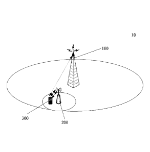
[0029] Figure 1 shows a scene of carrier aggregation for inter base-station
according to an
embodiment of the present disclosure. In the scene shown in Figure 1, a
wireless
communication system 10 includes a macro base station (corresponding to a
first base station
node) 100, a low power node (corresponding to a second base station node) 200
and a UE
(corresponding to a wireless communication device) 300. The UE 300 may
communicate with
the macro base station 100 and the low power node 200.
[0030] As shown in Figure 1, the macro base station 100 covers a wide coverage
area
referred to as a macro cell, and the low power node 200 covers a narrow
coverage area
referred to as a micro cell. There is no base band shared processing mode for
fiber direct
connection between the macro base station 100 and the low power node 200. The
UE 300
communicates with the macro base station 100 via a CC (Component Carrier) 1.
Meanwhile,
the UE 300 communicates with the low power node 200 via a CC2 and a CC3. In
which, the
CC1 is a communication main carrier of the UE 300 and the macro base station
100, and the
CC2 is a communication main carrier of the UE 300 and the low power node 200
(i.e., a
carrier of the low power node 200 for transmitting PUCCH). It should be noted
that, the CC1
is an uplink/downlink carrier pair in an FDD (Frequency Division Duplexing)
mode and is a
single carrier in a TDD mode, and the case also adapts to the CC2 and the CC3.
[0031] In Figure 1, a power of a signal transmitted from the UE 300 to the
macro base
station 100 and the low power node 200 simultaneously is too high. In an
embodiment of the
present disclosure, it is assumed that the UE 300 transmits data to two base
station nodes
simultaneously in case of the UE 300 being far away from the macro base
station 100, and in
- 7 -
CA 02932462 2016-06-02
this case a probability that an uplink total transmission power exceeds the
maximum
transmission power is high. In this example, the UE 300 determines whether it
is far away
from the macro base station 100 based on a downlink path loss of the macro
base station 100;
and the UE 300 notifies the network side to perform scheduling coordination
for inter
base-station to reduce a probability that frames overlap or symbols overlap,
if so. For example,
a probability that the uplink total transmission power exceeds the maximum
transmission
power for different distances between the UE and the macro base station may be
accounted in
advance, and a distance corresponding to a probability exceeding a threshold
is regarded as a
distance for which the UE is far away from the macro base station. In an
optional example,
the UE 300 determines whether it needs to transmit data to two base station
nodes
simultaneously based on scheduling information of an uplink signal from
respective base
stations for example; and the UE 300 may notify the network side to perform
scheduling
coordination for inter base-station to reduce a probability that frames
overlap or symbols
overlap, if so. In another example, the UE 300 may notify the network side to
perform
scheduling coordination for inter base-station to reduce a probability that
frames overlap or
symbols overlap only in a case that it is determined that the uplink total
transmission power
will exceed the maximum transmission power according to the scheduling
requirements to the
uplink signals from respective base stations.
[0032] According to the embodiments of the present disclosure, the macro base
station 100
may perform scheduling coordination with the low power node 200, so as to
reduce a
probability that the UE 300 transmits an uplink signal to the macro base
station 100 and the
low power node 200 simultaneously. Here, the scheduling coordination is
performed by the
macro base station 100. Preferably, the UE 300 may transmit the notification
for requesting
scheduling coordination for inter base-station to a scheduling coordination
device, i.e., the
macro base station 100. The present disclosure has no particular restriction
on the scheduling
coordination device. For example, the scheduling coordination may also be
performed by
assisting by the low power node 200 or other devices at the network side. For
facilitating
illustrating, it is assumed that the scheduling coordination is performed by
the macro base
station 100 for example hereinafter.
[0033] According to the embodiments of the present disclosure, in a case that
the UE 300
transmits an uplink signal to the macro base station 100 and the low power
node 200
simultaneously, transmission overlap of same subframes or transmission overlap
of symbols
-8.
CA 02932462 2016-06-02
between subframes occurs. Here, the uplink signal may include but not limited
to a PUCCH
signal, a PUSCH signal, an SRS signal and a PRACH signal.
[0034] According to the embodiments of the present disclosure, the UE 300 may
transmits
fewer uplink signals to the macro base station 100, so as to reduce the
probability that the UE
300 transmits the uplink signal to the macro base station 100 and the low
power node 200
simultaneously.
[0035] In a specific example of the present disclosure, after receiving the
notification for
requesting scheduling coordination for inter base-station transmitted by the
UE 300, the
macro base station 100 transmits a scheduling coordination request to the low
power node 200,
so as to request the low power node 200 to receive and forward, from the UE
300, an uplink
signal (for example a PUSCH) which was intended to be transmitted to the macro
base station
100. After obtaining the confirmation from the low power node 200, the macro
base station
100 transmits feedback information on scheduling coordination for inter base-
station to the
UE 300, so as to instruct the UE 300 to transmit the uplink signal which was
intended to be
transmitted to the macro base station 100 to the low power node 200. Ideally,
all the uplink
signals may be transferred to the low power node 200 for transmission. With
the above
method, in one hand, the uplink transmission power may be saved; and in the
other hand, the
probability that the PUSCH is transmitted to two base station nodes
simultaneously may be
reduced greatly. In this way, data transmission of the macro base station 100
only includes a
small amount of PUSCH (and PDSCH, transmission of PDSCH indicates PUCCH
feedback
of A/N, while the PUCCH will also feedback periodic CQI information)
transmission to
maintain RRC (Radio Resource Control) connection, channel quality measuring
reporting
(including mobility measuring and scheduling measuring), normal signaling
interaction and
other signaling interaction of carrier aggregation for inter base-station. In
this case, if the
downlink service from the macro base station 100 to the UE 300 is not
transferred to the low
power node 200 for transmission, a frequency of the PUCCH transmission
increases as the
downlink data transmission of the macro base station 100 increases, and
thereby increasing
the probability that the UE 300 transmits data to two base station nodes in
parallel and thereby
resulting in the transmission power exceeds the maximum transmission power.
Hence,
preferably, in the above examples of the present disclosure, the scheduling
coordination
request transmitted from the macro base station 100 to the low power node 200
further
includes a request that the low power node 200 receives, from the macro base
station 100,
- 9 -
CA 02932462 2016-06-02
downlink data (for example PDSCH) which was intended to be transmitted from
the macro
base station 100 to the UE 300 and forwards the downlink data to the UE 300.
[0036] Apparently, although it may be advised that all the services are
transferred to the low
power node 200 for transmitting as much as possible, the probability that the
performance is
reduced due to transmitting in parallel at the same time instant may be
further reduced by
coordinating.
[0037] Figure 2 shows a block diagram of a macro base station 100 according to
an
embodiment of the present disclosure. The macro base station 110 may adapt to
a scene in
which the wireless communication system is an FDD system, a TDD system or a
TDD and
FDD hybrid system. As shown in Figure 2, a selecting unit 130, a grouping unit
110 and an
assigning unit 120 may be provided in the macro base station 100.
[0038] The selecting unit 130 may select a reference configuration for
coordinating
subframe assignment of the macro base station 100 and the low power node 200
within a
scheduling coordination period. For example, in a case that the wireless
communication
system is the TDD system or the TDD and FDD hybrid system, uplink/downlink
matching for
respective carriers may be different. In this case, a reference configuration
for scheduling
coordination may be selected by the selecting unit 130.
[0039] Preferably, particularly in a case that connection carriers between the
UE 300, the
macro base station 100 and the low power node 200 each belongs to the FDD
standard or the
TDD standard with the same uplink/downlink matching, the uplink/downlink
reference
configuration may be set as a main carrier uplink/downlink configuration of a
main carrier of
the UE 300 at one of the macro base station 100 and the low power node 200.
[0040] Preferably, particularly in a case that the connection carriers between
the UE 300,
the macro base station 100 and the low power node 200 each is TDD carriers or
contains both
the FDD carrier and the TDD carrier, the uplink/downlink reference
configuration may be set
as a merging set uplink/downlink configuration formed by taking a merging set
for uplink
subframes of all carriers of the UE 300 at the one of the macro base station
100 and the low
power node 200.
[0041] Figure 3 shows an example of the above setting way of the
uplink/downlink
reference configuration. As shown in Figure 3, it is assumed that carries of
the UE 300 at the
-10-
CA 02932462 2016-06-02
macro base station 100 include a CCI of a configuration #2 adopting the TDD
standard and a
CC3 of a configuration #4 adopting the TDD standard, and carriers of the UE
300 at the low
power node 200 include a CC2 of a configuration #1 adopting the TDD standard
and a CC4
adopting the FDD standard.
100421 In carriers of the macro base station 100, the configuration #2
includes uplink
subframes 2 and 7, and the configuration #4 includes uplink subframes 2 and 3.
In case of
setting the uplink/downlink reference configuration of the macro base station
100, a merging
set may be taken for uplink subframes of the configuration #2 and the
configuration #4, so as
to obtain a merging set configuration 1. The merging set configuration 1
includes uplink
subframes 2, 3 and 7.
[0043] In carriers of the low power node 200, the configuration #1 includes
uplink
subframes 2, 3, 7 and 8. In addition, since the FDD standard does not have
fixed
uplink/downlink, it is considered by regarding all the subframes as uplink
subframes. In case
of setting the uplink/downlink reference configuration of the low power node
200, a merging
set may be taken for uplink subframes of the configuration #1 and the FDD
standard, so as to
obtain a merging set configuration 2. All the subframes in the merging set
configuration 2 are
uplink subframes. In this way, the merging set configuration 1 and the merging
set
configuration 2 include three overlapped uplink subframes, which may be
grouped as three
uplink subframe subgroups L1, L] and LII, as shown in Figure 3.
[0044] In a case that the uplink/downlink reference configuration adopts the
merging set
configuration mode, it needs to transmit a specific bitmap (for example, the
merging set
configuration 1 in Figure 3) to the macro base station 100 or the low power
node 200 for
notifying, which consumes resource. In order to avoid the issue, an existing
uplink/downlink
reference configuration being closest to the merging set uplink/downlink
configuration and
containing all of the uplink subframes in the merging set uplink/downlink
configuration, may
be selected from the existing 7 types of uplink/downlink configurations of the
TDD standard
as the uplink/downlink reference configuration. For example, as shown in
Figure 3, the
merging set configuration 1 includes uplink subframes 2, 3 and 7. An existing
uplink/downlink configuration being closest to the merging set configuration 1
and containing
all the uplink subframes 2, 3 and 7 in the merging set configuration 1 is the
configuration #1,
which includes uplink subframes 2, 3, 7 and 8. Hence, the configuration #1 may
be selected as
-11-
CA 02932462 2016-06-02
the uplinkJdownlink reference configuration. In this way, only a configuration
serial number
of the configuration #1 needs to be transmitted to the macro base station 100
or the low power
node 200 for notifying, and thereby saving resource.
[0045] In addition, in a case that one carrier of the UE 300 at the macro base
station 100 or
the low power node 200 has uplink subframes of remaining aggregated carries at
the same
time slot of one wireless frame, the uplink/downlink configuration of the
carrier with the most
uplink subframes directly functions as the reference configuration of the
macro base station
100 or the low power node 200. In addition, in a case that the connection
carriers between the
UE 300, the macro base station 100 and the low power node 200 each is TDD
carriers or
includes both FDD carriers and TDD carriers and no carrier of the UE 300 at
the macro base
station 100 or the low power node 200 has uplink subframes of the remaining
aggregated
carriers at the same time slot of one wireless frame, the reference
configuration may be set as
a configuration with the least uplink subframes and satisfying the following
condition: the
configuration has uplink subframes of all the aggregated carries on the macro
base station 100
or the low power node 200 at the same time slot of one wireless frame.
[0046] The grouping unit 110 may group uplink subframes overlapped within the
scheduling coordination period according to the uplink/downlink reference
configuration of
the macro base station 100 and the low power node 200, so as to obtain
multiple subframe
subgroups (for example, the subframe subgroups E, Hand L shown in Figure 3).
It should be
noted that, for facilitating illustration, Figure 3 is depicted based on the
same TA. In an actual
case, subframes of respective carriers may be not aligned, but the overlapped
subframes for
respective carries may be grouped as an uplink subframe subgroup.
[0047] The assigning unit 120 may assign at least a first subframe subgroup of
multiple
subframe subgroups to the macro base station 100 and assign at least a second
subframe
subgroup of multiple subframe subgroups to the low power node 200, so as to
coordinate
utilizing of possibly overlapping uplink subframes by the macro base station
100 and the low
power node 200. For example, in the first subframe subgroup, the UE 300 may
only transmit
a PUCCH signal, an SRS signal, a PRACH signal or an initially transmitted
PUSCH signal to
the macro base station 100; and in the second subframe subgroup, the UE 300
may only
transmit the PUCCH signal, the SRS signal, the PRACH signal or the initially
transmitted
PUSCH signal to the low power node 200. Within the scheduling coordination
period, if in
-12.
CA 02932462 2016-06-02
the initial transmission scheduling an uplink subframe is assigned by the
assigning unit 120 to
one base station node of the macro base station 100 and the low power node 200
for
scheduling, the other base station node of the macro base station 100 and the
low power node
200 cannot schedule all the sbuframes in a subframe subgroup to which the
uplink subframe
belongs to perform uplink initial transmission. In this way, a probability
that the UE 300
transmits an uplink signal as initially transmitted data to the macro base
station 100 and the
low power node 200 simultaneously is efficiently reduced.
[0048] In addition, in a case that time-continuous adjacent subframes are
assigned to the
macro base station 100 and the low power node 200 respectively, a subframe
subgroup to
which a subframe whose time is early belongs may be assigned by the assigning
unit 120 to a
base station node whose value of TA (Timing Advanced) of uplink transmission
time is larger
of the macro base station 100 and the low power node 200, for example the
macro base
station node 100, and a subframe subgroup to which a subframe whose time is
late belongs
may be assigned by the assigning unit 120 to a base station node whose value
of TA (Timing
Advanced) of uplink transmission time is smaller of the macro base station 100
and the low
power node 200, for example the low power node 200. In this way, symbol
overlapping may
be avoided better.
[0049] In a case that the uplink/downlink reference configurations for
coordinating
subframe assignment of the UE 300 at the macro base station 100 and the low
power node
200 belong to the TDD standard, a delaying unit 140 may be further provided in
the macro
base station 100, as shown in Figure 2. The delaying unit 140 may delay a
starting frame of
TDD wireless frames of one base station node of the macro base station 100 and
the low
power node 200 for several time slots (preferably, two time slots) than that
of the other base
station node of the macro base station 100 and the low power node 200.
Preferably, uplink
subframes or special subframes at same locations within different wireless
frames may be
grouped together. It should be noted that, the special subframes may transmit
an SRS, and
symbol overlapping between frames may occur, i.e., the SRS symbols of the
special
subframes overlap with PUCCH/PUSCH symbols of next subframes of other
carriers. Hence,
it is necessary to group uplink frames and uplink frames, uplink subframes and
special
subframes, or special subframes and special subframes together at the same
locations within
different wireless frames.
-13-
CA 02932462 2016-06-02
[0050] The above technical solution of the present disclosure is described in
detail in
conjunction with Figure 4. Figure 4 shows an uplinIddownlink matching of TDD.
Since for
the TDD the number of uplink subframes is limited, uplink resource shortage
will be further
intensified in a case that the macro base station 100 and the low power node
200 multiplex
uplink subframes in the time domain.
[0051] The delaying unit 140 may delay a starting frame of wireless frames of
one base
station node of the macro base station 100 and the low power node 200 for two
time slots than
that of the other base station node of the macro base station 100 and the low
power node 200,
so as to reduce the number of overlapped uplink subframes. For example, the
macro base
station 100 may calculate a subframe serial number based on one TDD matching
from a
certain time instant, and the low power node 200 may calculate a subframe
serial number
based on one TDD matching from two milliseconds (two time slots) after the
certain time
instant. Here, it is not limited to two time slots, as long as the number of
overlapped uplink
subframes can be further reduced.
[0052] Similarly, in this case, the grouping unit 110 may group uplink
subframes
overlapped within the scheduling coordination period, so as to obtain multiple
subframe
subgroups.
[0053] Furthermore, the assigning unit 120 may assign at least a first
subframe subgroup of
the multiple subframe subgroups to the macro base station 100, and assign at
least a second
subframe subgroup of the multiple subframe subgroups to the low power node
200. Here, in
the at least the first subframe subgroup, an uplink signal as initially
transmitted data is
transmitted to only the macro base station 100; and in the at least the second
subframe
subgroup, an uplink signal as initially transmitted data is transmitted to
only the low power
node 200. In this way, the probability that the UE 300 transmits the uplink
signal as initially
transmitted data to the macro base station 100 and the low power node 200
simultaneously is
efficiently reduced. The assigning unit 120 may assign uplink subframes for
which
transmission overlap occurs. Here, within the scheduling coordination period,
if in the initial
transmission scheduling an uplink subframe is assigned by the assigning unit
120 to one base
station node of the macro base station 100 and the low power node 200 for
scheduling, the
other base station node of the macro base station 100 and the low power node
200 cannot
schedule all the subframes in a subframe subgroup to which the uplink subframe
belongs to
-14-
CA 02932462 2016-06-02
perform uplink initial transmission.
[0054] As shown in Figure 4, in a case that a distance of n subframes (n=2) is
staggered
between wireless frames and since a subframe 0 and a subframe 1 in one
wireless frame are a
downlink subframe and a special subframe respectively, a subframe 2 is an
uplink subframe
certainly, a subframe 3 is also an uplink subframe other than in the
configurations 2 and 5, the
subframe 2 and the subframe 3 do not overlap in an uplink direction.
Particularly, for the
configurations 0, 1, 2 and 6, if two subframes are staggered in advance, not
only the uplink
subframes 2/3 do not overlap but also uplink subframes 7/8 do not overlap
either.
[0055] Practically, a shift operation of the wireless frame cannot completely
avoid overlap
of uplink subframes in various combinations of configurations. As shown in
Figure 5, uplink
subframs always overlap between configurations 0/3/6. Hence, the overlapped
subframe can
be provided to only one of the macro base station 100 and the low power node
200 for
PUCCH transmission and initial transmission of PUSCH/PRACH/SRS.
[0056] For configurations 1-5, since an RTT of an uplink HARQ is 10ms, initial
transmission and retransmission are performed in the same subframe, and
coordinating may
be performed between the macro base station 100 and the low power node 200
based on a
subframe serial number; subframes with the same serial number can be used by
one of the
macro base station 100 and the low power node 200, the subframe for initial
transmission and
the subframe for retransmission do not overlap, hence uplink subframes at the
same locations
in different wireless frames are grouped together, and subframe overlap may be
efficiently
avoided by taking multiples of 10ms as one coordinating period. In other
words, in a case that
uplink/downlink reference configurations for coordinating subframe assignment
of the UE
300 at the macro base station 100 and the low power node 200 belong to the TDD
standard,
uplink subframes or special subframes at same locations within different
wireless frames are
grouped together for an uplink/downlink matching whose RTT of the HARQ is
10ms. For the
configuration 0 and the configuration 6, since one uplink subframe is delayed
in each
retransmission, coordinating based on the subframe serial number only adapts
to the PUCCH
transmission and initial transmission of PUSCH/SRS/PRACH, the TDD grouping
solution
above may result in that subframe overlap occurs between initial transmission
or
retransmission of the node and retransmission or initial transmission of other
nodes.
Preferably, in case of the configurations 0 and 6, 2-5(configuration 0)
subframe subgroups and
-15-
CA 02932462 2016-06-02
2-4(configuration 6) subframe subgroups corresponding to continuous adjacent
uplink
subframes are assigned to the same node for uplink transmission, in this way,
a probability
that an uplink initial transmission and retransmission conflict occurs between
base station
nodes may be further reduced.
[0057] In the TDD coordinating scene, in a case that two base station nodes
use
time-continuous adjacent uplink subframes respectively, the base station node
with a larger
TA value uses the previous subframe, and the base station node with a smaller
TA value uses
the next subframe, in this way, interference between symbols of adjacent
subframes on
different carriers may be avoided.
[0058] Subsequently, a case that the wireless communication system is an FDD
system or
the wireless communication system is a TDD and FDD hybrid system and the
uplink/downlink reference configurations for coordinating subframe assignment
of the UE
300 at the macro base station 100 and the low power node 200 belong to an FDD
standard is
considered.
[0059] For example, in order to avoid frame overlap from occurring, an RTT
(Round-Trip
Time) of the FDD is 8ms, hence eight configuration subgroups (serial numbers 0-
7) are used
to perform scheduling coordination to avoid a scene of frame overlap between
initial
transmission and retransmission. In other words, in case of assigning and
coordinating FDD
carriers and the RTT of an HARQ (Hybrid Automatic Repeat Request) being 8ms,
subframes
whose serial numbers are the same after mode 8 are grouped together. A
specific
configuration may be set as follows (not limited to the example): it is
assumed that the
subframe serial number is a natural number, n=wireless frame serial
number*10+subframe
serial number (it should be noted that, the wireless frame serial number
ranges from 0 to the
maximum wireless frame serial number-1, and the subframe serial number may
range from 0
to 9), the configuration subgroup corresponding to the subframe serial number
is a value of
n%8. One configuration group can be used by only one base station node, which
base station
node using which configuration group is determined by a backhaul signaling
interaction
between two base station nodes according to the service volume. Specifically,
coordination
information for inter base-station may be confirmed by an interaction using a
logic X2 or an
51 interface for a wired backhaul. In a case that a certain uplink
configuration group is
determined to be used by the macro base station 100 or the low power node 200,
downlink
-16-
CA 02932462 2016-06-02
scheduling subframes corresponding to these uplink subframes (i.e., downlink
subframes for
the previous 4ms) can be used only by the macro base station 100 or the low
power node 200.
In addition, in order to avoid symbol overlap, in a case that two base station
nodes use
configurations whose serial numbers are adjacent, a base station node whose TA
value is
larger may use the configuration whose serial number is smaller. Particularly,
it should be
noted that a configuration subgroup 0 and a configuration subgroup 7 are
adjacent
configurations, and the configuration subgroup 7 is the configuration whose
serial number is
smaller. Particularly, a scheduling coordination period may be set as
multiples of 8ms, for
example 40ms, 80ms, 160ms, 320ms and so on.
[0060] Subsequently a case that the wireless communication system is the TDD
and FDD
hybrid system and the uplink/downlink reference configurations for
coordinating subframe
assignment of the UE 300 at the macro base station 100 and the low power node
200 belong
to different standards (i.e., one belongs to the TDD standard, and the other
belongs to the
FDD standard) is considered. In this case, a scheduling unit 150 may be
further provided in
the macro base station 100, as shown in Figure 2.
[0061] The scheduling unit 150 may schedule the UE 300, such that an uplink
signal is
transmitted to a base station node using an FDD uplink/downlink reference
configuration of
the macro base station 100 and the low power node 200 during only time slots
of downlink
subframes or special subframes of a base station node using a TDD
uplink/downlink reference
configuration of the macro base station 100 and the low power node 200, so as
to avoid uplink
subframe overlap.
[0062] Furthermore, the scheduling unit 150 may schedule the UE 300, such that
an uplink
signal is transmitted to one base station node of the macro base station 100
and the low power
node 200 over even subframes, and an uplink signal is transmitted to the other
base station
node of the macro base station 100 and the low power node 200 over odd
subframes.
[0063] According to the embodiment of the present disclosure, the UE 300
performs uplink
transmission of the FDD base station on the TDD downlink subframe, in this
way, a
probability of frame overlap may be reduced to some extent. However, the RTT
of the FDD is
8ms, the RTTs of configurations 1-5 in TDD are 10ms, uplink retransmission for
configurations 0 and 6 is always delayed for one uplink subframe from the
subframe for the
last transmission. Hence, coordinating based on the subframe serial number can
only avoid
-17-
CA 02932462 2016-06-02
frame overlap between initial transmission and initial transmission (i.e., the
PUCCH is
transmitted in the same subframes simultaneously), but cannot avoid subframe
overlap
between initial transmission data and retransmission data. The uplink
transmissions of the
FDD base station and the TDD base station are scheduled over the odd frames
and the even
frames in staggered serial number respectively, in this way, frame overlap
between initial
transmission and initial transmission and frame overlap between initial
transmission and
retransmission for configurations 1-5 of the FDD and the TDD can be avoided.
[0064] In the FDD and TDD hybrid coordinating scene, in a case that two base
station
nodes use time-continuous adjacent uplink subframes respectively, a base
station node whose
TA value is larger uses the previous subframe, and a base station node whose
TA value is
smaller uses the next sbuframe, thereby avoiding interference between symbols
of adjacent
subframes on different carriers.
[0065] Since the uplink transmission and the PUCCH feedback are caused by the
downlink
scheduling or the downlink data transmission, in the FDD scene, a downlink
scheduling
subframe corresponding to the uplink subframe is a subframe in the previous
4ms, and there is
one-to-one correspondence between them. In the TDD scene, for the PUCCH and
the PUSCH
of the uplink subframe, the PDSCH transmission and the PUSCH scheduling are
performed
on the corresponding downlink subframe, hence uplink scheduling coordination
also means
downlink scheduling coordination.
[0066] According to the embodiments of the present disclosure, the probability
that the UE
300 transmits the uplink signal to the macro base station 100 and the low
power node 200
simultaneously can be reduced as much as possible. When a case that the UE 300
transmits
the uplink signal to the macro base station 100 and the low power node 200
simultaneously
cannot be avoided completely, measures need to be taken to address the issue
of exceeding the
maximum transmission power in uplink transmission.
[0067] Figure 6 shows an overlap state of uplink transmission in a case that
no scheduling
coordination is performed between two network aggregated nodes. In which, for
a subframe 1
and a subframe 3, the UE 300 may transmit non-PUCCH data to the low power node
200 on a
CC2 or a CC3, and it is assumed that the UE 300 transmits the non-PUCCH data
on the CC2
for simplicity. Since the UE 300 is farther from the macro base station 100
than from the low
power node 200, an uplink signal for the CC1 is transmitted in advance
relative to an uplink
-18.
CA 02932462 2016-06-02
signal for the CC2/CC3 in the same subframe to ensure arrival synchronization
of the uplink
signals.
[0068] As shown in Figure 6, subframe overlap occurs in subframes 1, 3 and 4.
In a case
that a transmission power of the UE 300 is greater than the maximum
transmission power of
the UE 300 when the UE 300 transmits data on the CC1 and the CC2/CC3
simultaneously,
measures need to be taken to process the issue.
[0069] Figure 7 shows a block diagram of a wireless communication device
(i.e., a UE) 300
according to an embodiment of the present disclosure. As shown in Figure 7,
the wireless
communication device 300 may include a calculating unit 301, a transmission
power
restricting unit 302, an estimating unit 306, a probability accounting unit
303, a transmitting
unit 304 and a priority assigning unit 305.
[0070] The calculating unit 301 may calculate an uplink signal transmitting
power when the
wireless communication device 300 transmits an uplink signal to the macro base
station 100
and/or the low power node 200.
[0071] In a case that the uplink signal transmitting power calculated by the
calculating unit
301 exceeds a predetermined threshold, the transmitting power restricting unit
302 may
restrict the uplink signal transmitting power of the uplink signal, such that
an actual uplink
signal transmitting power does not exceed the predetermined threshold. The
estimating unit
306 may estimate an estimation probability that the uplink signal transmitting
power of the
wireless communication device 300 exceeds the predetermined threshold.
[0072] Furthermore, the probability accounting unit 303 may account an
accounting
probability that the uplink signal transmitting power exceeds the
predetermined threshold in
actual transmission.
[0073] The transmitting unit 304 may transmit the estimation probability
estimated by the
estimating unit 306 or the accounting probability accounted by the probability
accounting unit
303 to the macro base station 100. Based on the estimation probability
estimated by the
estimating unit 306 or the accounting probability accounted by the probability
accounting unit
303, the macro base station 100 may initiate scheduling coordination with the
low power node
200.
[0074] Furthermore, based on a path loss of a downlink carrier of the macro
base station
-19-
CA 02932462 2016-06-02
100, a path loss of a downlink carrier of the low power node 200 and an uplink
power control
parameter of the wireless communication device 300, the estimating unit 301
may estimate an
estimation probability that the uplink signal transmitting power exceeds the
predetermined
threshold.
[0075] Furthermore, the priority assigning unit 305 may assign a priority to
the uplink
signal.
[0076] In a case that the uplink signal transmitting power estimated by the
estimating unit
301 exceeds the predetermined threshold, the transmitting power restricting
unit 302 may
restrict, based on the priority of the uplink signal, the uplink signal
transmitting power of the
uplink signal by at least one of:
[0077] discarding an uplink signal with a lower priority;
[0078] transmitting the uplink signal with the lower priority by using uplink
signal
transmission power remained after a requirement for uplink signal transmission
power of an
uplink signal with a higher priority is satisfied;
[0079] performing power compression in proportion for uplink signals with a
same priority,
such that the compressed uplink signal transmission power does not exceed the
predetermined
threshold; and
[0080] performing muting process on the uplink signal with the lower priority
in a case that
only symbol overlap occurs.
10081] Furthermore, the priority assigning unit 305 may assign a priority to
the uplink
signal based on at least one of:
[0082] whether the uplink signal is initial transmitted data or retransmitted
data;
[0083] whether the uplink signal is a PUCCH signal, a PUSCH signal, an SRS
signal or a
PRACH signal;
[0084] whether the uplink signal is transmitted to the macro base station 100
or the low
power node 200;
[0085] whether the uplink signal is transmitted using FDD or TDD; and
[0086] whether the uplink signal is transmitted to a base station node with a
high or a low
uplink retransmission probability.
-20-
CA 02932462 2016-06-02
[0087] Specifically, referring to Figure 6, subframe overlap occurs in
subframes 1, 3 and 4.
In a case that the transmission power of the UE 300 is greater than the
maximum transmission
power of the UE 300 when the UE 300 transmits data on the CC1 and the CC2/CC3
simultaneously, the transmission power may be processed based on the principle
that multiple
uplink signals are transmitted on different carriers simultaneously (i.e., for
the data priority,
PRACH>PUCCH>PUSCH w/UCI (i.e., PUSCH carrying UCI)>PUSCH w/o UCI (i.e.,
PUSCH carrying no UCI)>SRS, where PUSCHs may share the same priority), except
the
following cases:
[0088] in a case that the transmission power is not sufficient for
transmitting PUSCH on the
CC1 and the CC2 simultaneously, PUCCHs for two carriers may be transmitted
after being
performed power compression in proportion; or PUCCH data of the CC2 or the CC1
is
transmitted using a power remained after a requirement for PUCCH transmission
power of
the CC1 or the CC2 is satisfied; or discarding CQI (Channel Quality
Indication) information
in a case that the power requirement can be satisfied after discarding
periodic CQI reporting
information; and discarding other transmission data with a low priority;
[0089] in a case that the transmission power is not sufficient for
transmitting PUSCH
carrying the UCI on the CC1 and the CC2/CC3 simultaneously, PUSCH for two
carriers may
be transmitted after being performed power compression in proportion; or PUSCH
data of the
CC2 or the CC1 is transmitted using the power remained after the PUSCH
transmission
power of the CC1 or the CC2 is satisfied, or discarding PUSCH data of the
CC2/CC1; or
discarding other transmission data with a low priority;
[0090] for the same type of data, it may be processed according to the
priority of the base
station node, for example, the transmission power of the macro base station
100 or the
transmission power of the base station node with a high retransmission
probability is
considered with a priority;
[0091] for the same type of data, it may be processed according to the
priority of a carrier
standard, for example, the power requirement of TDD is satisfied with a
priority, since the
uplink resource of TDD is less relative to that of the FDD; and
[0092] for the same type of data, it may be processed according to a priority
for initial
transmission or retransmission, for example, the priority for the initial
transmission is higher
than the priority for the retransmission, or the priority for the
retransmission is higher than the
-21-
CA 02932462 2016-06-02
priority for the initial transmission.
[0093] Particularly, in the subframe 2 shown in Figure 6, the transmission
power for frame
overlap and the carrier aggregation for intra base-station are processed in
the same way (i.e.,
for the data priority, PRACH>PUCCH>PUSCH w/UCI>PUSCH w/o UCI>SRS, where
PUSCHs may share the same priority).
[0094] After power assignment for respective carriers on the adjacent
subframes is
completed according to the transmission power processing principle for frame
overlap, it
needs to ensure that the overlapped power of overlapped symbols for subframes
2/3 and
overlapped symbols for subframes 3/4 does not exceed the maximum transmission
power by
the following ways:
[0095] the UE 300 transmits data for the CC1 or the CC2/CC3 in a muting way on
the
overlapped symbols (or transmitting with a zero power), so as to ensure that
the network can
still parse data with a low priority based on error correcting codes without
parsing the symbol
data correctly;
[0096] the UE 300 transmits data with a high priority on the overlapped
symbols firstly, and
then transmits data with a low priority using the remaining power;
[0097] for the transmission data with the same priority, the transmission
power thereof may
be compressed in proportion such that the transmission power does not exceed
the maximum
transmission power;
[0098] for the same type of data, it may be processed according to the
priority of the base
station node, for example, the transmission power of the macro base station
100 or the
transmission power of a base station node with a high/low retransmission
probability is
considered with a priority;
[0099] for the same type of data, it may be processed according to the
priority of a carrier
standard, for example, the power requirement of TDD is satisfied with a
priority, since the
uplink resource of TDD is less relative to that of FDD;
[00100] for the same type of data, it may be processed according the priority
for initial
transmission or retransmission, for example, the priority for the initial
transmission is higher
than the priority for the retransmission, or the priority for the
retransmission is higher than the
priority for the initial transmission; or
- 22 -
CA 02932462 2016-06-02
(001011 discarding an SRS signal with the lowest priority.
[00102] Particularly, according to the above processing ways, in case of
symbol overlap for
multiple TAs, the following scenes are to be increased in addition to the
scenes listed above:
[00103] in a case that symbol overlap occurs between PUCCH at the previous
subframe on
the CC1/CC2 and PUCCH at the next subframe on the CC2/CC1 and the total
transmission
power exceeds the maximum transmission power of the UE 300, it needs to ensure
that the
overlapped power does not exceed the maximum transmission power;
[00104] in a case that the CC1 and the CC2/CC3 transmit PUSCH w/UCI at the
previous
subframe and the next subframe of the overlapped symbols, it needs to ensure
that the
overlapped power does not exceed the maximum transmission power; and
[00105] in the previous subframe and the next subframe of the overlapped
symbol, for the
CC1 and the CC2/CC3, PUSCH w/UCI is transmitted at the previous subframe/next
subframe,
and PUSCH w/o UCI is transmitted at the next subframe/previous subframe, it
needs to
ensure that the overlapped power does not exceed the maximum transmission
power.
[00106] According to the embodiments of the present disclosure, in a case that
a wireless
cellular communication system performs carrier aggregation for inter base-
station adopting
the same or different standard in a heterogeneous network scene, simultaneous
transmission
on uplink carriers of different base station nodes can be avoided as much as
possible,
selection and adjustment may be performed based on different uplink signal
contents in a case
that simultaneous transmission is performed on uplink carriers of different
base station nodes,
such that the uplink transmission power does not exceed the maximum
transmission power of
the terminal.
[00107] Subsequently, a method for performing wireless communication in a
wireless
communication system is described. The wireless communication system may
include a first
base station node, a second based station node and a wireless communication
device
communicating with the first and second base station nodes. The method may
include:
performing, by the first and second base station node, scheduling
coordination, so as to reduce
a probability that the wireless communication device transmits an uplink
signal to the first and
second base station nodes simultaneously.
[00108] Preferably, the method according to an embodiment of the present
disclosure may
- 23 -
CA 02932462 2016-06-02
further include: selecting, by the first or second base station node,
uplink/downlink reference
configurations for coordinating subframe assignment of the first and second
base station
nodes within a scheduling coordination period; grouping, by the first or
second base station
node, uplink subframes overlapped within the scheduling coordination period
according to the
reference configurations of the first and second base station nodes;
assigning, by the first or
second base station node, at least a first subframe subgroup of multiple
subframe subgroups to
the first base station node, and assigning, by the first or second base
station node, at least a
second subframe subgroup of the multiple subframe subgroups to the second base
station
node, so as to coordinate utilizing of possibly overlapping uplink subframes
by the first and
second base station nodes.
[00109] Preferably, an uplink/downlink reference configuration of one of the
first and second
base station nodes may be set as any one of: a main carrier uplink/downlink
configuration of a
main carrier of the wireless communication device at one of the first and
second base station
nodes; a merging set uplink/downlink configuration formed by taking a merging
set for uplink
subframes of all carriers of the wireless communication device at the one of
the first and
second base station nodes; and an existing uplink/downlink configuration being
closest to the
merging set uplink/downlink configuration and containing all the uplink
subframes in the
merging set uplink/downlink configuration, which is selected from the existing
7 types of
uplink/downlink configurations of a TDD standard.
[00110] Preferably, the uplink/downlink reference configurations for
coordinating subframe
assignment of the wireless communication device at the first and second base
station nodes
may belong to the TDD standard. In this case, the method according to the
embodiment of the
present disclosure may further include: delaying, by the first or second base
station node, a
starting frame of TDD wireless frames of one of the first and second base
station nodes for
two time slots than that of the other of the first and second base station
nodes. Preferably,
uplink subframes or special subframes at same locations within different
wireless frames may
be grouped together.
[00111] Preferably, the reference configurations for coordinating subframe
assignment of the
wireless communication device at the first and second base station nodes may
belong to
different standards. In this case, the method according to the embodiment of
the present
disclosure may further include: scheduling, by the first or second base
station node, the
-24-
CA 02932462 2016-06-02
wireless communication device, such that an uplink signal is transmitted to a
base station
node using an FDD reference configuration of the first and second base station
nodes during
only time slots of downlink subframes or special subframes of a base station
node using a
TDD reference configuration of the first and second base station nodes.
[00112] Preferably, the first or second base station node may schedule the
wireless
communication device, such that an uplink signal is transmitted to one of the
first and second
base station nodes over even subframes, and an uplink signal is transmitted to
the other of the
first and second base station nodes over odd subframes.
[00113] Preferably, the reference configurations for coordinating subframe
assignment of the
wireless communication device at the first and second base station nodes may
belong to the
FDD standard, an RTT of the an 1-1ARQ is 8ms, and subframes whose serial
numbers are the
same after mode 8 are grouped together.
[00114] Preferably, in a case that time-continuous adjacent subframes are
assigned to the first
and second base station nodes, a subframe subgroup to which a subframe whose
time is early
belongs is assigned to a base station node whose value of TA (Timing advanced)
of uplink
transmission time is larger of the first and second base station nodes, and a
subframe
subgroup to which whose time is late belongs is assigned to a base station
node whose value
of TA (Timing advanced) of uplink transmission time is smaller of the first
and second base
station nodes.
[00115] With the wireless communication method according to the embodiments of
the
present disclosure described above, the probability that the wireless
communication device
transmits the uplink signal to the first and second base station nodes
simultaneously can be
reduced as much as possible. When a case that the wireless communication
device transmits
the uplink signal to the first and second base station nodes simultaneously
cannot be avoided
completely, measures need to be taken to address the issue of exceeding the
maximum
transmission power in uplink transmission.
[00116] Figure 8 shows a flowchart of a method for performing wireless
communication in a
wireless communication device in a wireless communication system according to
an
embodiment of the present disclosure.
[00117] As shown in Figure 8, in step S910, the wireless communication device
calculates
- 25 -
CA 02932462 2016-06-02
uplink signal transmission power when the wireless communication device
transmits an
uplink signal to the first and/or second base station node.
[00118] Subsequently, in step S920, in a case that the calculated uplink
signal transmission
power exceeds a predetermined threshold, the wireless communication device
restricts uplink
signal transmission power of the uplink signal, such that actual uplink signal
transmission
power does not exceed a predetermined threshold.
[00119] Subsequently, in step S930, an estimation probability that the uplink
signal
transmission power of the wireless communication device exceeds the
predetermined
threshold is estimated.
[00120] Subsequently, in step S940, an accounting probability that the uplink
signal
transmission power exceeds the predetermined threshold in actual transmission
is accounted.
[00121] Lastly, in step S950, the estimation probability or the accounting
probability is
transmitted to the first or second base station node.
[00122] Preferably, based on a path loss of a downlink carrier of the first
base station node, a
path loss of a downlink carrier of the second base station node and an uplink
power control
parameter of the wireless communication device, the wireless communication
device
estimates the estimation probability. Based on the estimation probability, the
first and second
base station nodes may initiate scheduling coordination with each other.
[00123] Preferably, based on the accounting probability, the first and second
base station
nodes may initiate scheduling coordination with each other.
[00124] Preferably, a priority may be assigned to an uplink signal by the
wireless
communication device. In a case that the estimated uplink signal transmission
power exceeds
a predetermined threshold, the wireless communication device may restrict,
based on the
priority of the uplink signal, the uplink signal transmission power of the
uplink signal by at
least one of:
[00125] discarding an uplink signal with a lower priority;
[00126] transmitting the uplink signal with the lower priority using uplink
signal
transmission power remained after a requirement for the uplink signal
transmission power of
the uplink signal with a higher priority is satisfied;
- 26 -
CA 02932462 2016-06-02
[00127] performing power compression in proportion on the uplink signals with
the same
priority, such that the compressed uplink signal transmission power does not
exceed a
predetermined threshold; and
[00128] performing muting processing on the uplink signal with the lower
priority in a case
that only symbol overlap occurs.
[00129] Preferably, the wireless communication device may assign a priority to
the uplink
signal based on at least one of:
[00130] whether the uplink signal is initially transmitted data or
retransmitted data;
[00131] whether the uplink signal is a PUCCH signal, a PUSCH signal, an SRS
signal or a
PRACH signal;
[00132] whether the uplink signal is transmitted to the macro base station or
the low power
node;
[00133] whether the uplink signal is transmitted using FDD or TDD; and
[00134] whether the uplink signal is transmitted to a base station node with a
high or a low
retransmission probability.
[00135] Specific implementation ways of various steps of the method for
performing
wireless communication in a wireless communication system according to the
embodiments
of the present disclosure are described in detail above, which are not
described here.
[00136] Apparently, various operation processes of the method for performing
wireless
communication in a wireless communication system according to the present
disclosure may
be implemented by computer executable programs stored in various machine
readable storage
mediums.
[00137] Furthermore, the object of the present disclosure may be implemented
by the
following way. A storage medium storing the executable program codes is
provided to the
system or device directly or indirectly, and a computer or a CPU (Central
Processing Unit) in
the system or device reads and executes the program codes. In this case, as
long as the system
or device has a function of performing programs, the implementation way of the
present
disclosure is not limited to programs, and the programs may have any form, for
example, an
object program, a program executed by an interpreter or scripts provided to
the operating
-27-
CA 02932462 2016-06-02
system or the like.
[00138] The machine readable storage medium includes but not limited to
various memories
and storage units, semiconductor devices, magnetic disk units for example an
optical disk, a
magnetic disk and a magnetic-optical disk, and other mediums adapting to
storage
information.
[00139] In addition, the computer, through a corresponding website connected
to the Internet,
downloads and installs the computer program codes according to the present
disclosure into
the computer and executes the program, thereby achieving the technical
solutions of the
present disclosure.
[00140] Figure 9 is an exemplary structural block diagram of a general purpose
personal
computer for performing the method for performing wireless communication in a
wireless
communication system according to an embodiment of the present disclosure.
[00141] As shown in Figure 9, a CPU 1301 performs various types of processing
according
to programs stored in a ROM (Read Only Memory) 1302 or programs loaded from a
storage
portion 1308 to an RAM (Random Access Memory) 1303. In the RAM 1303, data
required
when the CPU 1301 performs various types of processing may also be stored as
needed. The
CPU 1301, the ROM 1302 and the RAM 1303 are connected to each other via a bus
1304. An
input/output interface 1305 is also connected to the bus 1304.
[00142] The following components are connected to the input/output interface
1305: an input
portion 1306 (including a keyboard, a mouse and so on), an output portion 1307
(including a
display, for example a CRT (Cathode Ray Tube), an LCD (Liquid Crystal
Display), and a
loudspeaker and so on), a storage portion 1308 (including a hard disk and so
on) and a
communication portion 1309 (including a network interface card, such as an LAN
card and a
modem). The communication portion 1309 performs communication processing via a
network
such as the Internet. A driver 1310 may also be connected to the input/output
interface 1305
as needed. A removable medium 1311 for example a magnetic disk, an optical
disk, a
magnetic-optical disk, a semiconductor memory is installed on the driver 1310
as needed,
such that computer programs read from the removable medium 1311 are installed
into the
storage portion 1308 as needed.
[00143] In a case that the series of processing above is performed by
software, programs
-28-
CA 02932462 2016-06-02
constituting the software are installed from the network such as the Internet
or a storage
medium such as the removable medium 1311.
[00144] It should be understood by those skilled in the art that, the storage
medium is not
limited to the removable medium 1311 storing programs and transmitted
separately from the
device to the user to provide programs as shown in Figure 9. The removable
medium 1311
includes a magnetic disk (including a floppy disk (registered trademark)), an
optical disk
(including an CD-ROM (Compact Disk Read-Only Memory) and a Digital Versatile
Disk
(DVD)), a magnetic optical disk (including an MD (Mini Disk) (registered
trademark)) and a
semiconductor memory. Alternatively, the storage medium may be the ROM 1302, a
hard disk
contained in the storage portion 1308 and so on, in which programs are stored
and the storage
medium and the devices including the storage medium together are distributed
to the user.
[00145] It should be noted that, in addition to the wireless communication
system and the
method for performing wireless communication in a wireless communication
system
mentioned above, apparently according to the present disclosure, a base
station node in the
wireless communication system, a method for performing wireless communication
in the base
station node in the wireless communication system, a wireless communication
device in the
wireless communication system and a method for performing wireless
communication in the
wireless communication device of the wireless communication system are further
provided.
[00146] According to the embodiments of the present disclosure, a base station
node in a
wireless communication system is provided, and the wireless communication
system further
includes another base station node and a wireless communication device
communicating with
the base station node and the another base station node. In which, the base
station node and
the another base station node perform scheduling coordination, so as to reduce
a probability
that the wireless communication device transmits an uplink signal to the base
station node and
the another base station node simultaneously.
[00147] Preferably, the base station node is a macro base station, and the
another base
station node is a low power node.
[00148] Preferably, in a case that the wireless communication device transmits
the uplink
signal to the base station node and the another base station node
simultaneously, transmission
overlap of same subframes or symbol transmission overlap between subframes
occurs.
- 29 -
CA 02932462 2016-06-02
[00149] Preferably, the uplink signal includes a PUCCH (Physical Uplink
Control Channel)
signal, a PUSCH (Physical Uplink Shared Channel) signal, an SRS (Sounding
Reference
Signal) and a PRACH (Physical Random Access Channel) signal.
[00150] Preferably, a probability that the wireless communication device
transmits the uplink
signal to the base station node is reduced, thereby reducing the probability
that the wireless
communication device transmits the uplink signal to the base station node and
the another
base station node simultaneously.
[00151] Preferably, the base station node includes: a selecting unit for
selecting
uplink/downlink reference configurations for coordinating subframe assignment
of the base
station node and the another base station node within a scheduling
coordination period; a
grouping unit for grouping uplink subframes overlapped within the scheduling
coordination
period according to the reference configurations of the base station node and
the another base
station node, to obtain multiple subframe subgroups; and an assigning unit for
assigning at
least a first subframe subgroup of the multiple subframe subgroups to the base
station node
and assigning at least a second subframe subgroup of the multiple subframe
subgroups to the
another base station node, to coordinate utilizing of possibly overlapping
uplink subframes by
the base station node and the another base station node.
[00152] Preferably, an uplink/downlink reference configuration of one of the
base station
node and the another base station node may be set as any one of: a main
carrier
uplink/downlink configuration of a main carrier of the wireless communication
device at the
one of the base station node and the another base station node; a merging set
uplink/downlink
configuration formed by taking a merging set for uplink subframes of all
carriers of the
wireless communication device at the one of the base station node and the
another base
station node; and an existing uplink/downlink configuration being closest to
the merging set
uplink/downlink configuration and containing all the uplink subframes in the
merging set
uplink/downlink configuration, which is selected from the existing 7 types of
uplink/downlink
configurations of a TDD (Time Division Duplexing) standard.
[00153] Preferably, the reference configurations for coordinating subframe
assignment of the
wireless communication device at the base station node and the another base
station node
belong to the TDD (Time Division Duplexing) standard, and uplink subframes or
special
subframes at same locations within different wireless frames are grouped
together.
-30-
CA 02932462 2016-06-02
[00154] Preferably, the base station node further includes: a delaying unit
for delaying a
starting frame of TDD (Time Division Duplexing) wireless frames of one of the
base station
node and the another base station node for two time slots than that of the
other of the base
station node and the another base station node.
[00155] Preferably, the reference configurations for coordinating subframe
assignment of the
wireless communication device at the base station node and the another base
station node
belong to different standards, and the base station node includes: a
scheduling unit for
scheduling the wireless communication device, such that the uplink signal is
transmitted to a
base station using an FDD (Frequency Division Duplexing) reference
configuration of the
base station node and the another base station node during only time slots of
downlink
subframes or special subframes of a base station node using a TDD (Time
Division Duplexing)
reference configuration of the base station node and the another base station
node.
[00156] Preferably, the scheduling unit schedules the wireless communication
device, such
that the uplink signal is transmitted to one of the base station node and the
another base
station node over even subframes, and to the other of the base station node
and the another
base station node over odd subframes.
[00157] Preferably, the reference configurations for coordinating subframe
assignment of the
wireless communication device at the base station node and the another base
station node
belong to an FDD (Frequency Division Duplexing) standard, an RTT (Round-Trip
Time) of
an HARQ (Hybrid Automatic Repeat Request) is 8ms, and subframes whose serial
numbers
are the same after mod 8 are grouped together.
[00158] Preferably, in a case that time-continuous adjacent subframes are
assigned to the
base station node and the another base station node respectively, a subframe
subgroup to
which a subframe whose time is early belongs is assigned by the assigning unit
to a base
station node whose value of TA (Timing Advanced) of uplink transmission time
is larger of
the base station node and the another base station node, and a subframe
subgroup to which a
subframe whose time is late belongs is assigned by the assigning unit to a
base station node
whose value of TA (Timing Advanced) of uplink transmission is smaller of the
base station
node and the another base station node.
[00159] According to the embodiments of the present disclosure, a method for
performing
wireless communication in a base station node in a wireless communication
system is
-31-
CA 02932462 2016-06-02
provided, which includes: performing scheduling coordination with another base
station node
in the wireless communication system, to reduce a probability that the
wireless
communication device in the wireless communication system transmits the uplink
signal to
the base station node and the another base station node simultaneously.
[00160] Preferably, the method further includes: selecting, by the base
station node or the
another base station node, uplink/downlink reference configurations for
coordinating
subframe assignment of the base station node and the another base station node
within a
scheduling coordination period; grouping, by the base station node or the
another base station
node, uplink subframes overlapped within the scheduling coordination period
according to the
reference configurations of the base station node and the another base station
node, to obtain
multiple subframe subgroups; assigning, by the base station node or the
another base station
node, at least a first subframe subgroup of the multiple subframe subgroups to
the base station
node, and assigning, by the base station node or the another base station
node, at least a
second subframe subgroup of the multiple subframe subgroups to the another
base station
node, to coordinate utilizing of possibly overlapping uplink subframes by the
base station
node and the another base station node.
[00161] Preferably, the uplink/downlink reference configuration of one of the
base station
node and the another base station node may be set as any one of: a main
carrier
uplink/downlink configuration of a main carrier of the wireless communication
device at the
one of the base station node and the another base station node; a merging set
uplink/downlink
configuration formed by taking a merging set of uplink subframes of all
carriers of the
wireless communication device at the one of the base station node and the
another base
station node; and an existing uplink/downlink configuration being closest to
the merging set
uplink/downlink configuration and containing all uplink subframes in the
merging set
uplink/downlink configuration, which is selected from the existing 7 types of
uplink/downlink
configurations of a TDD (Time Division Duplexing) standard.
[00162] Preferably, uplink subframes or special subframes at same locations
within different
wireless frames are grouped together.
[00163] Preferably, the reference configurations for coordinating subframe
assignment of the
wireless communication device at the base station node and the another base
station node
belong to a TDD (Time Division Duplexing) standard, and the method further
includes:
- 32 -
CA 02932462 2016-06-02
delaying a starting frame of TDD (Time Division Duplexing) wireless frames of
one of the
base station node and the another base station node for two time slots than
that of the other of
the base station node and the another base station node.
[00164] Preferably, the reference configurations for coordinating subframe
assignment of the
wireless communication device at the base station node and the another base
station node
belong to different standards, and the method further includes: scheduling the
wireless
communication device, such that the uplink signal is transmitted to a base
station node using
an FDD (Frequency Division Duplexing) reference configuration of the base
station node and
the another base station node during only time slots of downlink subframes or
special
subframes of a base station node using a TDD (Time Division Duplexing)
reference
configuration of the base station node and the another base station node.
[00165] Preferably, the base station node schedules the wireless communication
device, such
that the uplink signal is transmitted to one of the base station node and the
another base
station node over even subframes, and to the other of the base station node
and the another
base station node over odd subframes.
[00166] Preferably, the reference configurations for coordinating subframe
assignment of the
wireless communication device at the base station node and the another base
station node
belong to an FDD (Frequency Division Duplexing) standard, an RTT (Round-Trip
Time) of
an HARQ (Hybrid Automatic Repeat Request) is 8 ms, and subframes whose serial
numbers
are the same after mod 8 are grouped together.
[00167] Preferably, in a case that time-continuous adjacent subframes are
assigned to the
base station node and the another base station node respectively, a subframe
group to which a
subframe whose time is early belongs is assigned to a base station node whose
value of TA
(Timing Advanced) of uplink transmission time is larger of the base station
node and the
another base station node, and a subframe group to which a subframe whose time
is late
belongs is assigned to a base station node whose value of TA (Timing Advanced)
of uplink
transmission time is smaller of the base station node and the another base
station node.
[00168] According to the embodiments of the present disclosure, a wireless
communication
device in a wireless communication system is provided, which includes: a
calculating unit for
calculating uplink signal transmission power when the wireless communication
device
transmits an uplink signal to a first and/or second base station node in the
wireless
- 33 -
CA 02932462 2016-06-02
communication system; a transmission power restricting unit for restricting
the uplink signal
transmission power of the uplink signal in a case that the uplink signal
transmission power
calculated by the calculating unit exceeds a predetermined threshold, such
that actual uplink
signal transmission power does not exceed the predetermined threshold; an
estimating unit for
estimating an estimation probability that the uplink signal transmission power
of the wireless
communication device exceeds the predetermined threshold; a probability
accounting unit for
accounting an accounting probability that the uplink signal transmission power
exceeds the
predetermined threshold in actual transmission; and a transmitting unit for
transmitting the
estimation probability or the accounting probability to the first or second
base station node.
[00169] Preferably, based on a path loss of a downlink carrier of the first
base station node, a
path loss of,a downlink carrier of the second base station node and an uplink
power control
parameter of the wireless communication device, the estimating unit estimates
the estimation
probability; and based on the estimation probability, the first and second
base station nodes
initiate scheduling coordination with each other.
[00170] Preferably, based on the accounting probability, the first and second
base station
nodes initiate scheduling coordination with each other.
[00171] Preferably, the wireless communication device further includes: a
priority assigning
unit for assigning a priority to the uplink signal, where in a case that the
uplink signal
transmission power estimated by the estimating unit exceeds the predetermined
threshold, the
transmission power restricting unit restricts, based on the priority of the
uplink signal, the
uplink signal transmission power of the uplink signal by at least one of:
discarding an uplink
signal with a lower priority; transmitting the uplink signal with the lower
priority using uplink
signal transmission power remained after a requirement for the uplink signal
transmission
power of an uplink signal with a higher priority is satisfied; performing
power compression in
proportion for uplink signals with the same priority, such that the compressed
uplink signal
transmission power does not exceed the predetermined threshold; and performing
muting
processing on uplink signals with the lower priority in a case that only
symbol overlap occurs.
[00172] Preferably, the priority assigning unit assigns the priority to the
uplink signal based
on at least one of: whether the uplink signal is initial transmitted data or
retransmitted data;
whether the uplink signal is a PUCCH (Physical Uplink Control Channel) signal,
a PUSCH
(Physical Uplink Shared Channel) signal, an SRS (Sounding Reference Signal) or
a PRACH
- 34 -
CA 02932462 2016-06-02
(Physical Random Access Channel) signal; whether the uplink signal is
transmitted to the
macro base station or the low power node; whether the uplink signal is
transmitted using FDD
(Frequency Division Duplexing) or TDD (Time Division Duplexing); and whether
the uplink
signal is transmitted to a base station node with a high or low retransmission
probability.
[00173] According to the embodiments of the present disclosure, a method for
performing
wireless communication in a wireless communication device in a wireless
communication
system is provided, which includes: calculating uplink signal transmission
power when the
wireless communication device transmits an uplink signal to a first and/or
second base station
node in the wireless communication system; restricting, by the wireless
communication
device, uplink signal transmission power of the uplink signal, in a case that
the calculated
uplink signal transmission power exceeds a predetermined threshold, such that
actual uplink
signal transmission power does not exceed the predetermined threshold;
estimating an
estimation probability that the uplink signal transmission power of the
wireless
communication device exceeds the predetermined threshold; accounting an
accounting
probability that the uplink signal transmission power exceeds the
predetermined threshold in
actual transmission; and transmitting the estimation probability or the
accounting probability
to the first or second base station node.
[00174] Preferably, based on a path loss of a downlink carrier of the first
base station node, a
path loss of a downlink carrier of the second base station node and an uplink
power control
parameter of the wireless communication device, the wireless communication
device
estimates the estimation probability; and based on the estimation probability,
the first and
second base station nodes initiate scheduling coordination with each other.
[00175] Preferably, based on the accounting probability, the first and second
base station
nodes initiate scheduling coordination with each other.
[00176] Preferably, the method further includes: assigning a priority to the
uplink signal,
where in a case that the estimated uplink signal transmission power exceeds
the
predetermined threshold, the uplink signal transmission power of the uplink
signal is
restricted based on the priority of the uplink signal by at least one of:
discarding an uplink
signal with a lower priority; transmitting the uplink signal with lower
priority using uplink
signal transmission power remained after a requirement for the uplink signal
transmission
power of an uplink signal with a higher priority is satisfied; performing
power compression in
- 35 -
CA 02932462 2016-06-02
proportion for uplink signals with the same priority, such that the compressed
uplink signal
transmission power does not exceed the predetermined threshold; and performing
muting
processing on the uplink signal with the lower priority in a case that only
symbol overlap
occurs.
[00177] Preferably, a priority is assigned to the uplink signal based on at
least one of:
whether the uplink signal is initially transmitted data or retransmitted data;
whether the uplink
signal is a PUCCH (Physical Uplink Control Channel) signal, a PUSCH (Physical
Uplink
Shared Channel) signal, an SRS (Sounding Reference Signal) or a PRACH
(Physical Random
Access Channel) signal; whether the uplink signal is transmitted to the macro
base station or
the low power node; whether the uplink signal is transmitted using FDD
(Frequency Division
Duplexing) or TDD (Time Division Duplexing); and whether the uplink signal is
transmitted
to a base station node with a high or low retransmission probability.
[00178] In the system and method of the present disclosure, it is obvious that
respective
components or steps can be decomposed and/or recombined. Such decomposition
and/or
recombination should be considered as an equivalent solution of the present
disclosure. And,
the steps performing a series of processing above can be performed in the
describing order
naturally, but this is not necessary. Some steps can be performed concurrently
or
independently with one another.
[00179] Although the embodiments of the present disclosure have been described
in detail in
combination with the drawings above, it should be understood that, the
embodiments
described above are only used to explain the present disclosure and is not
constructed as the
limitation to the present disclosure. For those skilled in the art, various
modifications and
alternations can be made to the above embodiments without departing from the
essential and
scope of the present disclosure. Therefore, the scope of the present
disclosure is only defined
by the appended claims and the equivalents thereof
-36-