Note: Descriptions are shown in the official language in which they were submitted.
CA 02932602 2016-06-02
PCT/RU2014/000916 ¨ English Translation
FAST NEUTRON REACTOR AND NEUTRON REFLECTOR BLOCK OF A FAST
NEUTRON REACTOR
Field of the Invention
The invention relates to the field of nuclear engineering, and more
particularly to heavy
liquid metal-cooled fast neutron reactors containing removable neutron
reflector blocks.
Prior Art
The prior art discloses heavy liquid metal-cooled fast neutron reactors
containing
reflector blocks [see http://www.atomic-energy.ru/technology/36000], [Patent
RU 2408094
published on 12/27/2012].
The following requirements are imposed on reflector blocks of heavy liquid
metal-cooled fast neutron reactors: protection of non-removable and non-
reloadable shells
of the reactor plant located outside of the reflector from neutron and gamma
radiation;
minimizing the coolant flow through reflector blocks, as the volumetric energy
release in
steel structures of the reflector is less than that in fuel rods by 2-3 times
or more, and the
coolant flow for the reflector block cooling chills down the coolant coming
from the fuel rod
part of the core by mixing with it; minimizing the content of structural
materials in the reflector
blocks cross section to reduce parasitic neutron capture.
Currently, nuclear power plants (NPP) with operating sodium-cooled fast
neutron
reactors use the design wherein the reflector blocks consist of three parts:
head section,
middle part, and a shank. Such reflector blocks are mounted to the reactor
header supplying
coolant for block cooling with the shank. Sodium coolant in the blocks is
throttled using
washers installed into the core space of the blocks, and sodium-washing
coolant in the
space between the blocks is throttled outside the shank via barb connection,
and at the top
of the casing using washers. All of the above throttling structures in the
sodium coolant are
rather compact since the local sodium rate may be increased up to 8.-10 m/s,
and throttling
flow paths may be designed with a small cross-sectional area for the coolant.
CA 02932602 2016-06-02
PCTIRU2014/000916 ¨ English Translation
Implementation of the Invention
The task to be solved by the group of inventions is to design a fast neutron
reactor
reflector block improving the thermohydraulics of the heavy liquid metal-
cooled reactor plant
by providing for the upper and lower limits for the heavy liquid metal coolant
in terms a
structure washing rate.
The technical result of the claimed group of inventions is an increase in the
operating
safety of a fast neutron reactor based on the reduced temperature of fuel
claddings reached
by means of the coolant temperature equalization along the core radius; an
increase in the
performance of a fast neutron reactor based on the increased coolant medium
mixing
temperature at the core outlet, i. e. the temperature of the coolant to have
passed the fuel
rod part of the core, and the temperature of the coolant to have passed the
reflector block,
reached by increasing the temperature of the coolant to have passed through
the reflector
block.
The claimed technical result is achieved as a fast neutron reactor contains a
core
consisting of heavy liquid metal-cooled fuel rods, and neutron reflector
blocks disposed
around the core, which comprise a casing with at least one inlet opening in
the side walls
thereof, the said inlet opening being intended for diverting part of the
coolant flow from the
space between the blocks into the casing, at least one vertical pipe mounted
in the casing,
through which the diverted coolant flow, passing through the upper and lower
boundaries of
the core, enters the bottom part of the casing, and on the outer side of the
casing, above the
inlet opening, and a throttling device is mounted for creating hydraulic
resistance to the
coolant flow in the space between the blocks.
The claimed technical result is achieved as a neutron reflector block of a
fast neutron
reactor comprises a casing with at least one inlet opening in the side walls
thereof, the said
inlet opening being intended for diverting part of the coolant flow from the
space between the
blocks into the casing, at least one vertical pipe mounted in the casing,
through which the
diverted coolant flow enters the bottom part of the casing, and a throttling
device mounted
on the outer side of the casing, above the inlet opening, for creating
hydraulic resistance to
the coolant flow in the space between the blocks.
2
CA 02932602 2016-06-02
PCT/RU2014/000916 ¨ English Translation
The coolant passes between the reflector blocks and then through 30 openings
in the
casing walls and through the vertical pipes, and flows between the lower (core
inlet) and
upper (core outlet) boundaries of the core three times; thus, the coolant is
heated three
times more due to absorption of radiation in the coolant itself, and due to
consistent heating
along the coolant flow path in the cooling process of reflector block steel
structures releasing
energy associated with ionizing radiation absorption. Therefore, instead of
using throttling
devices with a high local coolant flow rate, the coolant flow is redirected to
a longer flow
path, where a higher hydraulic resistance is achieved both by the coolant flow
path turns
inside the reflector block casing and by friction losses along the longer flow
path. At the
same time, the reflector block hydraulic resistance increases, and the
reflector blocks and
fuel rods run in parallel in the hydraulic reactor plant primary circuit, i.
e. the general
hydraulic differences in the core respond to the same. Hence, a greater
coolant flow rate
will be directed to the fuel rod part of the core. This ensures equalization
of the increasing
coolant temperature along the core radius.
Temperature equalization of the coolant flowing through the core and the
reflector
blocks allows to reduce the maximum temperature of fuel cladding (hot-spot
temperature) by
increasing the coolant flow entering the fuel rods of the core. This is one of
the main limiting
factors in determination of the performance criteria for fuel claddings in the
heavy liquid
metal-cooled fast neutron reactor.
Furthermore, in a specific embodiment of the invention, vertical pipes are
connected to
the casing above the upper core boundary.
Furthermore, in a specific embodiment of the invention, the neutron reflector
block
casing is made of martensite-ferrite structural steel.
Furthermore, in a specific embodiment of the invention, the neutron reflector
block
.. further comprises a shank.
Disclosing Information
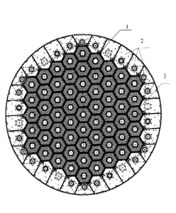
Fig. 1 ¨ layout of the reactor core elements for triangular arrangement of
fuel rods;
Fig. 2 ¨ reflector block (longitudinal section);
3
The fast neutron reactor with the elements layout shown in Figure 1 comprises
a
core (1) consisting of fuel rods (2), with a heavy liquid metal coolant,
primarily lead or
an eutectic of lead and bismuth. The core (1) has a lower boundary H1 (core
inlet) and
an upper boundary H2 (core outlet). The neutron reflector blocks (3) are
disposed
around the core (1). They are designed to reduce neutron leakage and return
the same
to the core (1).
The neutron reflector block shown on Figure 2 comprises a steel casing (4)
with
at least one inlet opening (5) in the side walls thereof, intended for
diverting part of the
coolant flow (6) from the space between the blocks into the casing and into
the return
header (51), at least one vertical pipe (7), through which the diverted
coolant flow (6)
enters the bottom part of the casing (4), the said pipe being connected
thereto through
the header (51) by means of welding. Vertical pipes (7) may be installed along
the
longitudinal axis of the reflector block or may be twisted against its
longitudinal axis. A
throttling device (8) is mounted on the outer side of the casing (4): at its
top, in the
section from inlet opening (5) to the reflector block outlet. Its design shall
provide for
an increase in the coolant flow from the space between the blocks into the
casing (4)
by creating hydraulic resistance substantial for the diverted coolant flow in
the vertical
section of the space between blocks, wherein the coolant rate in the
throttling
device (8) shall not exceed 2+2.5 m/s in order to reduce erosion/corrosion on
the
washed casing (4) walls. In a preferred embodiment, the throttling device (8)
comprises an overlay steel plate with one side welded to the casing (4) wall,
the said
plate being graded or corrugated from the casing wall surface to improve the
coolant
flow thereunder. The overlay plate is slotted in order to adjust the flow rate
of the
coolant flowing under the overlay plate by setting the width and length of
cuts. The
.. outer side of the overlay plate of one reflector block shall be in contact
with or gapped
apart from the outer side of the overlay plate of the adjacent reflector
block. To
increase the performance of the throttling device (8), overlay plates shall be
placed
upon each casing (4) wall of the reflector block above the upper core boundary
(H2) to
cover all gaps between the reflector blocks. The reflector block casing (4)
wall under
the overlay plate of the throttling device (8) may be tapered to increase the
coolant
flow under the plate. The reflector block further includes a shank (9) to be
mounted to
the reactor base. The preferred embodiment may have the reflector block casing
(4)
made of
4
Date Recue/Date Received 2021-06-07
CA 02932602 2016-06-02
PCT/RU2014/000916 ¨ English Translation
of martensite-ferrite structural steel, as this class of steel is resistant to
corrosion when used
in a heavy liquid metal coolant medium, and maintains good plastic properties
under the
condition of high neutron irradiation. It is preferred to mount vertical pipes
(7) in the
casing (4) above the upper boundary (H2) of the core (1) instead of mounting
between the
lower (H1) and upper (H2) boundaries of the core (1), in order to reduce
irradiation
embrittlement of welded joints at the pipe (7) connection points, as higher
neutron fluxes
pass between H1 and H2 of the core (1), and as the coolant flow path increases
with the
openings upward offset along the casing of the reflector block. The reflector
block casing (4)
may have a triangular, square, hexagonal or other optional form in the cross
section,
depending on the arrangement of fuel rods (2) used.
Mode of Operation
Fuel assemblies with fuel rods (2) are loaded into the fast neutron reactor
core (1). The
neutron reflector blocks (3) are disposed around the core (1) so that the
inlet openings (5) in
the side walls of the casing (4) are located above the upper boundary (H2) of
the core (1).
Thus, the coolant flow (6) part passing through the upper boundary (H2) of the
core (1)
enters the reflector block casing (4) from the space between the blocks
through the
openings (5) and the header (51), i.e. it turns 900 from the concurrent
coolant flow between
the blocks from bottom to the top. Then, by turning another 90 the diverted
flow (6) flows
downstream to the bottom part of the casing (4) through the vertical pipes
(7), passing
through the upper boundary (H2) of the core (1). Then, the coolant flow (6)
turns 180 and
flows upstream in the casing (4), again passing through the lower (H1) and
upper (H2) of the
core (1) until it leaves the reflector block casing (4).
Thus, the proposed hydraulic circuit of the diverted coolant flow (6) in the
reflector
block casing (4) allows to increase heating of the coolant passing through the
reflector block
and equalization of the coolant heating temperature along the core (1) radius
in the mixing
zone: i. e. where coolant flows to have passed through fuel rods and the
reflector block are
mixed as a part of the coolant flow to have passed between the reflectors
passes between
the upper (H2) and lower (H1) boundaries of the core (1) three times and,
thus, it is heated
5
CA 02932602 2016-06-02
PCT/RU2014/000916 ¨ English Translation
three times more by absorbing radiation in the coolant and by mans of
consistent heating
when releasing energy from the reflector block (3) steel structures. When
equalizing the
temperature profile along the core (1) radius, the medium mixing temperature
of the coolant
above the upper core (1) boundary (H2) is also increased. Medium mixing
temperature is the
.. temperature reached when mixing coolant flows to have passed fuel rods of
the core (1) and
those to have passed through the reflector block (3). Such equalization occurs
due to the
increasing temperature of the coolant to have passed through the reflector
block (3). By
increasing the coolant medium mixing temperature at the upper boundary (H2) of
the
core (1), the reactor plant performance is increased, i. e. power output
through the
secondary circuit coolant in the turbine (omitted for clarity) may be
increased at the same
thermal power output in the core (1). The enthalpy of water increases at the
same flow rate
of the secondary circuit. By increasing the medium mixing temperature at the
core (1) outlet,
the heat exchange surface in steam generators may be reduced at the same
secondary
circuit power output (omitted for clarity).
6