Note: Descriptions are shown in the official language in which they were submitted.
CA 02932656 2016-06-02
WO 2015/084162
PCT/NL2014/050782
TITLE
TORREFACTION/GASSIFICATION SYSTEM
FIELD OF THE INVENTION
This invention relates to torrefaction systems and more particularly to an
environmentally safe fire and explosion resistant system in which a standard
commercial
vibratory dryer is modified to provide a reactor.
BACKGROUND OF THE INVENTION
Torrefaction, or the roasting of a biomass such as wood chips and the like,
has
been used in the past to produce biocoal, which is packaged as a briquette or
pellet that
can be utilized to replace fossil fuel. The biocoal is characterized by high
energy density,
homogeneity, is hydrophobic, exhibits no biologic activity and offers improved
grindability, making the torrefied product not only coming from a sustainable
source such
as renewable wood supplies but also is environmentally sound, oftentimes when
directly
replacing natural coal eliminating CO2 emissions.
In replacing fossil fuels biocoal may be used as a wood power fuel, in steel
production, in centralized heating and as a clean stock for production of
transportation
fuels such as methanol.
As exemplified by the present plant at Stamproy Green, biocoal is produced
utilizing a standard commercial dryer that has been modified into a
torrefaction reactor.
It is noted that the original Carrier dryer was designed to recirculate air
for a number of
drying applications in order to remove moisture from product. The modification
of the
1
CA 02932656 2016-06-02
WO 2015/084162
PCT/NL2014/050782
Stamproy Green reactor involves modifying the dryer with a perforated plate
onto which
biomass in the form of wood chips are deposited at one end, and through which
hot
synthetic wood gas or syngas is passed to roast or torrefy the wood in a
convective
heating operation. The reactor, fed by an inlet airlock device such as a
screw, is vibrated
causing the roasted or torrefied wood chips to move down the perforated plate
to the exit
port where the torrefied material is collected by an outlet airlock device
such as a screw.
In this manner the reactor remains air tight and the torrefied biomass while
roasting
produces syngas which is subsequently recirculated through the dryer.
It is noted that in this prior modification of the Carrier dryer there are no
moving
parts within the reactor and there were very few changes needed to the dryer
itself, other
than external air locks, to make it suitable for use as a convective
torrefaction reactor.
The changes in the commercial Carrier dryer to accommodate torrefaction
include
modifying the above-mentioned perforated plate and to provide an external
burner to
combust a small amount of excess evolving syngas and an external heat
exchanger to
then heat the larger volume of recirculated syngas so it can be injected into
the bottom of
the reactor. The external piping of hot syngas poses a severe fire hazard,
especially
outside the reactor. Because the reactor is vibratory and the piping in the
facility is fixed,
numerous flexible connections are used and each poses a safety concern.
It is noted that syngas is extremely flammable and in the presence of oxygen
rapidly combusts or could potentially explode. The hotter the syngas the
higher the
likelihood of explosion. Because the existing oxidizer burner output is at
about 800
degrees C, an extremely hazardous situation exists outside the reactor due to
the
2
CA 02932656 2016-06-02
WO 2015/084162
PCT/NL2014/050782
superheated flue gas from this burner. This superheated fluegas is heat
exchanged with
recirculated syngas from the reactor to ideally produce injected recirculated
syngas at
300-400 degrees C, but as high as 500 C, requiring a special heat exchanger
that can
cope with high differential temperatures of 800 C on one side and 300 C on the
other
side. The control of the energy balance between the two sources is problematic
and non
linear in nature. This heat exchanger also poses a safety risk and is located
outside of the
reactor.
It is noted that torrefaction ideally takes place at between 250 C and 300 C,
and
is to take place in an oxygen-free environment. Aside from the situation of
potential
leaks outside the reactor, if there is oxygen leakage into the reactor, the
syngas that
normally evolves during the torrefaction process can explode causing rupture
of the
reactor or at the very least a significant thermal runaway event that would
damage the
equipment. When operating at 300 C the evolving syngas creates a massive
safety risk,
with any leak involving flammable hot gas looking for oxygen. Also leakage can
cause
the release of deadly carbon monoxide. Add to this the risks associated with
external
burners and 500 C heated syngas ported to the bottom of the reactor through
ductwork,
present torrefaction installations are exceedingly dangerous.
The leakage danger in vibrating torrefaction reactors is due to the inherent
vibration conveying design that loosens the couplings or deforms the coupling
material
itself between the reaction chamber which is vibrating and the conduits or
duct work
which are fixed to pipe the syngas which is evolved in the torrefaction
process. The
present modified Carrier dryers have as many as 15 ducting conduits coupled to
the sides
3
CA 02932656 2016-06-02
WO 2015/084162
PCT/NL2014/050782
of the reactor. At each of these large pipes or conduits is a gland which is a
flexible
coupling to be able to absorb the vibration of the reactor, with the flexible
joints between
the fixed conduits and the vibrating reactor designed to prevent the leakage
of oxygen
into the reactor and to prevent outflow of gases developed in the reactor.
However it has
been found that there are frequent failures of these glands making such
torrefaction
systems unsafe as air/syngas leaks are not only difficult to prevent, but also
difficult to
detect in this process environment.
The Stamproy Green modification of the standard Carrier dryer for torrefaction
thus results in numerous ports of entry for oxygen due to the failure of
glands around the
conduits utilized to duct the waste products from the torrefaction process
either to outside
the plant or to be used in a heat recapture process to recycle heated gas to
the bottom of
the reaction chamber.
As will be appreciated it is important to provide a reaction chamber in which
oxygen cannot inadvertently leak in and cause fires or explosions. It has been
the
experience of torrefaction plants in the past that fire is the major cause of
failure of the
plant and there is therefore an urgent requirement that such reactors be
constructed in a
different manner to minimize the possibility of the influx of oxygen that can
cause
explosion or the venting of dangerous gas components or the exhaust of
dangerous gases
at these glands. Also there is a requirement to increase the efficiency of the
system to be
able to better utilize the energy associated with evolved syngas to provide a
source of
electricity to run the process and to capture useful waste heat.
4
CA 02932656 2016-06-02
WO 2015/084162
PCT/NL2014/050782
In addition to the leakage problem noted above, an even further problem with
the
Stamproy Green plant is thermal runaway. Thermal runaway occurs when reactor
temperatures cannot be controlled. This is the result of the inability to
sufficiently
remove energy from the evolving process. Currently aside from slowing down the
biomass feed stock supply which can take as long as 30 minutes to be
effective, to kill
thermal runaway the entire plant has to be shut down. In terms of production
this is
unacceptable. Thus there is an urgent need to be able to control thermal
runaway by
including a process element to remove energy from the system.
More particularly, and as mentioned above, in the Stamproy Green plant syngas
which is the evolved product in torrefaction, is coupled to a burner which
heats the 300 C
syngas by the burning some of the syngas to create 800 C fluegas.
Additionally, syngas
which is not coupled to the burner is collected by utilizing a blower and it
is directed into
a heat exchanger in which the 300 C syngas is heated by the 800 C fluegas
output of the
burner to provide as high as a 500 C syngas that is injected into the bottom
of the reactor.
Thereafter and through convective heating the hot gas passes through the
aforementioned
perforated plate and into the overlying biomass in the form of wood chips at
which point
the wood chips are torrefied or roasted.
As stated above, this process includes a large number of inlet and exhaust
conduits, which can number as many as 15, each having its own flexible gland
at which
air and therefore oxygen can enter into the reactor upon gland rupture.
This process is indeed dangerous due to the many conduits associated with the
reactor as well as for instance the highly heated burner output which is
ducted to the
CA 02932656 2016-06-02
WO 2015/084162
PCT/NL2014/050782
reactor. It will be appreciated that that which is injected into the reactor
is not inert gas
but rather a highly volatile heated syngas which if mixed with oxygen can
result in
explosions, fire or thermal runaway.
SUMMARY OF INVENTION
In order to make the torrefaction process less dangerous, rather than using
all of
the 15 available ventilation ports on the dryer, all but three of these ports
are sealed off,
one for syngas and two for flue gas, to significantly limit potential syngas
leakage due to
gland rupture from the vibrating reactor. In one embodiment, the number of
conduits
associated with the carrier reactor are limited to a single syngas bleed to
power a gas
engine and an inlet conduit to take the engine exhaust from the gas engine and
inject it
into the bottom of the reactor below an unperforated solid waffle plate that
divides the
reactor into an upper and lower compartment or plenum along with a second
outlet
conduit for the flue gas.
This solid plate is heated with non-volatile exhaust gas from the engine such
that
the only volatile and flammable gas in the reactor exists in the upper plenum
or chamber
in the form of syngas. The heated plate conductively transfers heat to the top
chamber
and biomass as opposed to using convective heating which in the past has
involved the
whole reactor chamber, ducts, blower, heat exchanger, all full of flammable
gas. Here
because of the sealing of the solid plate into the reactor to provide the two
plenums or
chambers, only inert gas from the exhaust of the gas engine is injected into
the reactor.
Note, there is only one syngas conduit with significantly less ducting,
thereby
decreasing by orders of magnitude the danger of explosions and fires. Thus, in
one
6
CA 02932656 2016-06-02
WO 2015/084162
PCT/NL2014/050782
embodiment 8 of the original output ports from the Carrier dryer are simply
blocked off,
thereby minimizing the number of leakage points in the modified reactor to
only one, that
being the syngas port to the gas generator.
Secondly, rather than drawing off and mixing syngas with combustion air to a
burner fueled by the syngas, in one embodiment an internal combustion gas
engine is
fueled by the evolving syngas, with the non-volatile exhaust gas of the engine
injected
into the bottom chamber of the reactor. This non-volatile exhaust gas includes
nitrogen,
CO2 and a small amount of oxygen and arrives beneath the solid plate at about
500 C.
As a result an external burner with its associated 800 C flue gas exhaust and
its
associated external heat exchanger, the cause of dangerous operation, is
completely
eliminated.
The use of non-volatile exhaust gas from the gas engine also opens up the
opportunity to control reactor temperature by injecting cold air into the
exhaust gas for
dilution and cooling of the reactor. Such could not be done with the
recirculated hot
syngas used in the Stamproy Green plant. In one embodiment, thermal runaway is
prevented by the injection of cold air into the inert exhaust gas stream from
the gas
engine to cool the non-volatile exhaust gas that fuels the reactor. Cold air
introduction is
controlled by a damper that is in turn controlled by the temperatures sensed
at the exhaust
gas input to the reactor and syngas outlet of the reactor, the pressure of the
syngas
utilized to fuel the gas engine and the current generated by an electrical
generator driven
by the gas engine. As a result, cold air damping provides an even flue gas
temperature at
the underside of the unperforated plate within the reactor, with fires and
explosions
7
CA 02932656 2016-06-02
WO 2015/084162
PCT/NL2014/050782
further minimized by the utilization of a cool air damper. Moreover, and
thermal
runaway can be prevented immediately.
Because the evolving syngas is utilized to fuel a gas engine, in one
embodiment
the gas engine is used to drive the above-mentioned electric generator for
energy
recovery. It is noted that the utilization of the syngas-powered gas engine
with an electric
generator recovers otherwise potentially wasted energy from the process which
may be
utilized elsewhere in the plant, while at the same time providing a current
sensor,
indicative of load, for the control of the process. While temperature and
pressure are
useful control parameters, generator current coupled with voltage gives an
indication of
the energy (kWh) removed from the reactor, which is very useful for process
control.
Further, the sealing of the top chamber or plenum of the reactor from the
bottom
chamber or plenum using a solid plate isolates the potentially dangerous
syngas to only
the top chamber of the reactor where leakage can be more readily controlled.
Furthermore, having only clean inert flue gas in the bottom chamber of the
reactor allows
for thermal insulation to be placed inside the reactor in addition to or in
lieu of external
insulation. Internal insulation, akin to that used in a thermal oxidizer,
allows for higher
500 C flue gas temperatures without adversely affecting the structural
integrity of the
steel reactor.
In summary the modified dryer operates on a different principle from that used
by
the prior torrefaction plants. The subject invention utilizes thermal
conduction to torrefy
the biomass in a vibratory reactor in which a heated solid unperforated plate
is sealed in
the reactor to separate the biomass above from the gas used to heat the plate
below. This
8
CA 02932656 2016-06-02
WO 2015/084162
PCT/NL2014/050782
permits using inert flue gas to heat the reactor which in turn permits the use
of a cool air
damping system to prevent thermal runaway. Also syngas evolved from the
process is
utilized to power a gas engine, the exhaust output of which is recirculated to
heat the
reactor plate. When the gas engine is coupled to an electric generator, waste
energy is
recovered for use in other parts of the plant or exported elsewhere.
BRIEF DESCRIPTION OF THE DRAWINGS
These and other features of the subject invention will be better understood in
connection with the Detailed Description, in conjunction with the Drawings, of
which:
Figure 1 is a diagrammatic illustration of a typical prior art vibratory dryer
which
has been modified for torrefaction showing the vibration of the reactor;
Figure 2 is a diagrammatic illustration of the reactor of Figure 1 showing the
number of the conduits used in the prior art dryer which are attached to the
reactor
through flexible couplings in which the flexible couplings may rupture during
torrefaction;
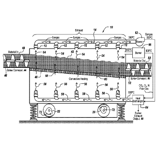
Figure 3 is a diagrammatic illustration of a prior art torrefaction system
utilizing a
vibrating dryer in which the biomass is extruded onto a perforated plate and
in which hot
gas passes up through the plate in a convective heating process whereupon
synthetic gas
or syngas is evolved and is mixed with the output of a burner in a heat
exchanger to
provide heated gas for the torrefaction process;
Figure 4 is a diagrammatic illustration of the operation of the prior art
torrefaction
system of Figure 3 illustrating both convective heating, a perforated plate,
the utilization
9
CA 02932656 2016-06-02
WO 2015/084162
PCT/NL2014/050782
of syngas bled off in the process which is utilized to fuel a burner that in
turn is coupled
to a heat exchanger to heat the syngas from the reactor for providing heated
syngas to the
bottom of the perforated plate;
Figure 5 is a diagrammatic illustration of one embodiment of the subject
invention
in which the standard vibrating dryer is converted to a conductive heating
process
through the use of a solid inclined plate which is heated from below with the
output from
a gas engine fueled by the syngas that is evolving from the torrefaction
process, also
illustrating the injection of cold air through a damper to prevent thermal
runaway;
Figure 6 is a diagrammatic illustration of a portion of the reactor shown in
Figure
to illustrate the utilization of a solid plate that seals the reactor chamber
into a bottom
plenum and a top plenum, with reactor heat provided by the exhaust from a gas
engine;
Figure 7 is a diagrammatic illustration of the system shown in Figure 6 which
includes the utilization of a damper to inject cool air into an inert gas
stream from the gas
engine powered by the syngas evolving from the biomass, with the gas engine
driving a
generator and with the damper controlled by the pressure of the syngas at the
input to the
gas engine, the temperature of the hot gas delivered from the damper to the
bottom
plenum and by detecting removed energy in terms of the current generated by
the
generator, thus to provide stable control of the damper to prevent thermal
runaway; and,
Figure 8 is a diagrammatic illustration of the sealing of the reactor with a
solid yet
undulating plate underneath which is injected 500 C hot gas, with the syngas
evolving
from the torrefaction of the biomass exiting at about 300 C.
CA 02932656 2016-06-02
WO 2015/084162
PCT/NL2014/050782
DETAILED DESCRIPTION
Prior Art
Referring now to Figure 1, a reactor 10 in the form of a modified Carrier
vibratory
dryer includes syngas ducting conduits 12 which are coupled to a manifold 14
for
capturing the syngas generated by the reactor. As illustrated, off center
weights in
modules 16 cause the entire reactor to vibrate as illustrated by the dotted
lines 18, with
reactor mounted on springs 20 to permit the vibrating. Here the biomass is
introduced at
duct work 22 so that it travels down the interior of the reactor to produce
biocoal.
Referring to Figure 2, the other side of reactor 10 is shown in which duct
work 12
is shown coupled to the aforementioned manifold 14, with the joints between
the duct
work and the portions of the conduit 12' joined through the utilization of a
gland 24
which permits movement between conduits 12 and 12' with the motion 18 of
reactor 10
and manifold 14. Also shown are inlet conduits 30 which have glands 24
interposed
between conduits 30 and the exterior portions 30', with the input to the
reactor being
supplied by a manifold 32 into which hot gas is to be introduced.
Here it can be seen that the vibration of reactor 10 is accommodated through
glands or flexible joints 24 which, inter alia, must be capable of porting the
hot syngas at
300 C out of the reactor and be able to port heated syngas into the bottom of
the reactor.
It is noted that the vibratory dryer is modified in this prior art
installation in which
the commercial dryer is used to migrate material through the dryer with no
moving parts.
In essence for this prior art installation there were very few changes
necessary to convert
the vibratory dryer to a torrefaction reactor. The first physical change made
is that a
11
CA 02932656 2016-06-02
WO 2015/084162
PCT/NL2014/050782
modified perforated plate is used within the dryer to support the biomass
which
incorporates wood chips that for instance tend to turn to dust. The dust as it
will be
appreciated will fall through the holes in the perforated plate as originally
supplied.
How this prior art reactor works is shown in Figure 3 in which reactor 10 is
provided with a perforated plate 40 that heats the wood chip biomass 42 that
has been
injected into the reactor through a screw conveyor 44, with the biomass
completely filling
the void between the screw conveyer impellers 46 and the exterior conduit 48
of the
conveyer. It will be appreciated that this screw conveyer does not allow
ingress of
oxygen into reactor 10, with the reactor being sealed by the biomass itself.
At the distal
end of the perforated plate is a cooling screw conveyer 50 also having a screw
52 in
which biomass 42 completely fills the space between the screw conveyer and its
outer
conduit 54, again sealing the reactor against the influx of oxygen. As will be
discussed if
the reactor is unsealed there is a possibility for fire or explosion of the
syngas 54 which
evolves from biomass 42 during the torrefaction process.
The torrefaction process starts with providing heated gas 56 beneath
perforated
plate 40 such that it passes through orifices 58 in plate 40 and then passes
as illustrated at
60 through the wood chip biomass to roast or torrefy the wood chips such that
what exits
screw conveyor 50 in one embodiment is biocoal or briquettes due to the
roasting or
torrefaction process. The efficiency of the torrefaction process is defined by
the energy
output from the process in the form of biocoal divided by the energy input to
the process
in the form of biomass, typically wood. The net energy lost in the process is
in the form
12
CA 02932656 2016-06-02
WO 2015/084162
PCT/NL2014/050782
of syngas evolved which functionally is lost from the process as radiated or
exhausted
heat.
In order to capture and utilize waste heat from the process, syngas 54 is
piped
through the aforementioned conduits 12 and manifold 14 to a blower 62 such
that the
evolving 300 C syngas is forced out of the blower and into a heat exchanger
64. The
ideal heat for the convective heating shown in Figure 3 is on the order of 400
C to
500 C, with torrefaction resulting in 300 C syngas. Heat exchanger 64 is fed
by an
800 C burner 66 output which transfers thermal energy to the 300 C syngas to
provide
the heated syngas 56 in manifold 32. It is noted that in one embodiment in the
heat
exchanger is provided with cylindrical tubing which transfers the heat from
the burner
output to the syngas, with the burner exhaust output being as illustrated at
68.
Here it can be seen that off center weights 70 rotating as illustrated by
arrows 72
cause reactor 10 to vibrate so as to move the biomass from screw conveyor 44
to screw
conveyor 50.
Referring now to Figure 4, schematically syngas 54 is bled out of reactor 10
to
burner 66 whereupon an 800 C burner output as illustrated at 74 is mixed with
a high
volume syngas output at conduit 76 provided by blower fan 62.
Here it can be seen through the thickness of arrows 74 and 76 that the flow
rate
from the burner is significantly less than the massive flow rate output of 62
which may be
for instance as low as 250 C. As illustrated at manifold 32 a heated low
volume syngas
output at 500 C is mixed with the high volume output from fan 62 such that the
13
CA 02932656 2016-06-02
WO 2015/084162
PCT/NL2014/050782
temperature of the syngas from the blower is heat augmented using the output
of burner
66.
As mentioned above, the physical change to the commercial carrier vibratory
dryer includes the utilization of a modified perforated plate in which the
apertures in the
plate are sized to minimize the amount of dust that can fall through the holes
when hot
gases are moving upwardly through the apertures in the plate. In one
embodiment, not
shown, small covers are placed over the holes such that the dust is not
allowed to fall
back down through the holes.
The second change for the commercial vibratory dryer is that the dryer is no
longer drying materials, i.e. removing moisture, other than wood but is now
heated to a
temperature which will roast the wood chips and is much like putting wood into
a frying
pan, with the wood giving off flammable gases such as methane, hydrogen,
acetic acid
and carbon monoxide.
The end result is that instead of using a unit which circulates air in a
drying
process, in a torrefaction application what is actually generated is
recirculated syngas. It
will be appreciated that synthetic gas or syngas is a low BTU gas that can be
generated
for instance from landfill gas and more particularly from wood or from coal.
Syngas is
used instead of methane which has a heat value of 1,000 BTU per cubic foot
because of
its ready availability and low cost. Specifically the range for syngas is on
the order of
200 to 400 BTU such that what is utilized in the torrefaction process is a low
BTU
synthetic gas.
14
CA 02932656 2016-06-02
WO 2015/084162
PCT/NL2014/050782
Safety
a) Reducing number of conduits
In the above prior art torrefaction process there is a considerable safety
concern
because syngas has replaced air in the dryer and the temperature of the dryer
in the
torrefaction process is on the order of 300 C as opposed to for instance 60 C
for
commercial drying. At these higher temperatures with syngas one creates a
massive
safety risk such that any leak is going to involve a flammable hot gas that is
looking for
oxygen.
It is noted that the prior art reactor is intended to be a closed system in
which the
leakage of oxygen into the reactor is specifically to be avoided. In practice
upon starting
up of the system a small amount of oxygen is consumed in regular combustion.
For the
first 10 to 15 minutes the wood that is on top of the perforated plate is
actually
combusting. Once all of the oxygen is consumed one is creating more and more
syngas
and this is done in an oxygen-free environment thereafter recirculation of the
syngas is
ultimately used to produce heat to drive the process.
In the prior art reactors of Figures 1 and 2 there is perhaps 200 to 300 feet
of
external duct work which is fixed but must be connected to the violently
vibrating
reactor. . As pointed out above there are physical connections between the
pipe work
which isn't vibrating and the unit which is vibrating. Because of the
vibration the
aforementioned glands have ruptured and many leaks and fires have been caused
at the
facility in which the Carrier dryers have been modified with conventional
flexible
connections.
CA 02932656 2016-06-02
WO 2015/084162
PCT/NL2014/050782
Originally the flexible connections were made out of fabric but the fabric
could
not handle the temperatures and would eventually rupture and result in leaks.
Thereafter
the glands were made in the form of a convoluted stainless steel expansion
bellows
system which partially mitigated the problem and were able to handle the high
temperatures. However, the vibration in and of itself loosened these glands
and with as
many as 15 of these metal connections if any one of them leaks it puts syngas
into the
facility and is an ever present risk. Also because syngas is predominantly
carbon
monoxide, health and safety of the employees in such a plant are also a
significant risk.
Thus, the plugging of most of the holes for the prior art conduits
significantly
reduces the possibility of fire or explosion due to the fact that only one
syngas joint or
flange need be addressed for maintenance purposes. Note also that whatever
syngas is
utilized exists only within the reactor and that the utilization of an
external recirculating
blower and external heat exchanger is eliminated, thereby eliminating the
flammable
syngas recirculation loop of the prior art system shown in Figures 3 and 4.
Significant modifications to the standard vibratory dryer first and foremost
include closing all but one of the ducts that are used to recirculate the
syngas. This can
be seen in Figure 5 in which a single pipe or conduit 80 is utilized to bleed
the evolving
syngas 54 to a cooler 82 to remove tar as illustrated at arrow 84, with the
output 86 of the
cooler coupled to a gas engine 88 to which is attached an electrical generator
in one
embodiment. As will be seen, the output of the gas engine 90 is non-volatile
and
substantially inert, although some oxygen remains. This gas engine output
exits at
16
CA 02932656 2016-06-02
WO 2015/084162
PCT/NL2014/050782
approximately 500 C which is then injected through conduit 92 as illustrated
by arrow 94
into the bottom portion of reactor 10.
b) Conductive heating and the use of a solid torrefaction plate
It will be seen that rather than using convective heating, in the subject
application
a solid plate 100 is utilized to support biomass 42 which comes in from screw
conveyer
44 and exits from that screw conveyer 50. Here the hot inert gas is
illustrated at 102 to
impinge upon the lower surface of plate 100 where it heats the plate to 500 C.
It will be
appreciated that biomass 42 is roasted in very much the same way as using a
frying pan
in which the biomass is cooked on top of plate 100. Note that convective
elements within
the top portion of the reactor itself facilitate internal convention much like
a convection
oven but without the need to remove or recirculate the syngas from the
reactor.
What will also be appreciated is that plate 100 is sealed to the ends 104 and
106
of chamber 10, thereby to divide chamber 10 into a lower chamber or plenum 110
and an
upper chamber or plenum 112. The result is that while inert gas from gas
engine 88 is
utilized to heat plate 100, the only portion of the reactor at which flammable
gas exists is
above plate 100 and with the utilization of only one conduit 80 the leakage
associated
with the vibration is minimized.
It is noted that the feedstock, namely the wood chips input, exist at
approximately
20 C, whereas the torrefied material exits at a relatively hot 300 C due to
the torrefaction
that takes place above plate 100. This material is subsequently cooled back to
20 C by
the outlet screw to stop the torrefaction process.
17
CA 02932656 2016-06-02
WO 2015/084162
PCT/NL2014/050782
c) Thermal runaway
As will be discussed more completely hereinafter, thermal runaway is
controlled
by the ingress of cold air 114 using a cold air blower 116 and a damper and
valve
assembly 118 such that the non-volatile exhaust gas from engine 88 may be
cooled
through the ingestion of cold air from outside. It is noted that since only
the upper
chamber contains flammable gas and since the exhaust output from the gas
engine
includes nitrogen, CO2 and 02, the control of the heat applied to plate 100
can be rapidly
controlled through this cold air damper system.
As will be discussed, a control unit or module 120 controls damper assembly
118
through the output of a thermal couple sensor 122 at conduit 92, a pressure
transducer
124 which measures the pressure in conduit 80, and a current sensor 126 which
senses the
energy removed from the reactor by the gas engine in terms of the current and
the
kilowatt-hours generated. It will be seen that a balancing of the temperature,
pressure and
electric current output can effectively modulate the temperature of the
incoming gas at 94
so as to stabilize the temperature of the gas applied to the bottom of plate
100.
System Details
It will be appreciated that all of the syngas evolving from the subject
process is
leaving the reactor through a single pipe as shown in Figure 6 by the
schematic of plant
operation. Here all of the evolving syngas 54 leaves through pipe 80 and is
applied to
fuel a reciprocating spark ignition gas engine 88 which in this case has a
generator 124
18
CA 02932656 2016-06-02
WO 2015/084162
PCT/NL2014/050782
mechanically coupled to the gas engine to provide electric current as
illustrated at 126.
As seen, the use of plate 100 involves conductive heating as illustrated at
130 as opposed
to convective heating in the prior installations. Moreover, plate 100 may be a
waffle
plate 100' to offer more surface area to transfer energy from plenum or
chamber 110 to
the biomass on plate 100'. Thus it can be seen that the subject reactor
operates on
conductive heating with a solid plate bifurcating the reactor and in which
inert gas from a
gas engine is utilized to fuel the reactor.
While a gas engine has been described other types of syngas fired heating
units
may be utilized such as a gas turbine, burner or a boiler. However because a
gas engine
also provides a rotary output to drive an electric generator as illustrated by
dotted line
128 the electrical energy generated may be used by the plant to power the
vibrating
motors and other plant equipment as well as sell the unused electricity to the
grid.
Referring back to Figure 5 it will be appreciated that cooler 82 cools the
syngas
down to room temperature to be able to remove tars that drop out. What then
happens is
that the syngas is then ducted to a combustion source; gas turbine, burner,
boiler or a gas
engine, with the gas engine preferred since it may be used to generate
electricity
efficiently. It is noted that the cooler is utilized to condense the tars out
so as not to foul
or coke up the gas engine pistons. Tars are very much like creosote and if
they can be
separated out from the system their recovery provides for another reactor
product. The
tars can also be utilized as a binder to glue the torrefied powder together
into biocoal
briquettes or pellets.
19
CA 02932656 2016-06-02
WO 2015/084162
PCT/NL2014/050782
It is noted that the hot flue gas from the gas engine is ducted to the bottom
plenum
110 with one pipe and while there is some oxygen left over in the combustion
flue gas
from the gas engine, the output from the gas engine is predominantly nitrogen
and carbon
dioxide which is non-volatile and basically inert. This inert gas is
completely safe as far
as employees are concerned and as the utilization of this inert flue gas
limits the
possibility of explosion. It will be appreciated that the output gas from the
engine is
around 500 C, whereas the syngas is around 300 to 400 C. It is this
differential
temperature that is utilized in the drive heat transfer. If there is
insufficient heat transfer
from the plate to the biomass one can actually introduce a fan into the upper
plenum or
chamber to stir up the evolving syngas very much like a convection oven to
help with
transfer. However in most instances this is not necessary.
In summary, the subject system utilizes conduction to transfer heat from the
exhaust gas in the lower plenum to the upper plenum and then into the biomass
itself. It
is noted that gas engines are utilized because they can run on low energy
fuels such as
syngas at high efficiency as well as across a wide variety of load. These gas
engines are
readily available especially from engine manufacturers supplying landfill
companies and
are particularly appropriate for use in the subject system because the exit
temperature of
the gas is exactly that which is necessary to heat the reactor. The gas engine
is also very
efficient in producing electricity making it a good additional profit center.
Thermal Efficiency
It is noted that prior torrefaction plants have exhibited an average 50-60%
thermal
efficiency in part because the amount of evolved syngas cannot be adequately
controlled
CA 02932656 2016-06-02
WO 2015/084162
PCT/NL2014/050782
and the excess heat generated is lost. Those that use boilers to extract heat
to make steam
might have a 66-67% thermal efficiency. However using a syngas fueled gas
engine and
electrical generator raises the overall thermal efficiency to as high as 80%.
In operation one does not initially have syngas. To start up the reactor one
first
starts up the engine utilizing natural gas to fire and idle the gas engine.
Very little natural
gas is utilized to initially power the gas engine and in point of fact the gas
engine only
idles when starting on natural gas. Once heated the reactor is actively made
inert with
steam and inert nitrogen so that no combustion happens in the reactor. Biomass
is
introduced slowly at first until syngas is evolved. Then the engine power
increases
allowing for biomass input to increase and the process slowly ramps up.
It will be appreciated that for torrefied wood ideally 20 percent of the input
wood
energy is turned into syngas and subsequently heat and the rest of the energy
comes out
as biocoal. This biocoal is a brown to black product.
The problem with respect to thermal runaway is that when wood is torrefied at
250 C to 300 C about 40 percent of the thermal energy within the wood when
torrefying
wood is volatile at these temperatures and managing the process so that only
20% is
evolved is an exacting control issue requiring razor sharp response time and
also the
ability to both add and remove heat from the process. One wants to utilize
only 20
percent of the heat, because anything more would be wasted. If one cannot soak
up the
remaining 20 percent of the torrefaction heat generated, the process tends to
want to run
away. This is because the process wants everything that is volatile at 340 C
to exit the
wood. This in turn makes most torrefaction processes very inefficient.
21
CA 02932656 2016-06-02
WO 2015/084162
PCT/NL2014/050782
Efficiency and Thermal Runaway
It is also this inability to utilize the heat that is generated in the process
which
causes thermal runaway that leads to high reactor temperatures, fires and a
large number
of other safety concerns. Thus what is required in the torrefaction process is
roasting the
wood such that only 20 percent of the input heat is used to cook the wood. It
will be
appreciated that the increased heat over the 20 percent produces more
volatiles and the
process tends to run away with no safety features built in to prevent thermal
runaway in
the prior torrefaction processes.
Referring now to Figure 7, in one embodiment thermal runaway is prevented
utilizing damper assembly 118 through the introduction of cold air 114 through
conduit
92 into bottom plenum or chamber 110 of reactor 10. As described above the
damper is
controlled by the temperature at pipe 92 as sensed by thermocouple 122, by the
pressure
transducer 124 which measures the pressure in pipe 80 and by the current
generated at
current detector 130 associated with generator 124 to detect energy removed
from the
system.
Thus the air damper system shown in Figure 7 is utilized to stabilize the
amount
of volatiles that are being generated.
It will be noted that combustion in a gas engine is relatively stable from the
exhaust temperature standpoint, known for a given load although the volume of
exhaust
also changes making load indication a valuable control signal. Thus this
design is
inherently more stable than the prior designs, with the advantage of the gas
engine being
that the gas engines are about 40 percent thermally efficient across a wide
variety of
22
CA 02932656 2016-06-02
WO 2015/084162
PCT/NL2014/050782
loads. In short these engines are exceptional thermal conversion machines.
They are
much better for instance than boiler steam power plants which are typically
about 20%
thermally efficient. Thus of the 40 percent volatiles syngas energy available
if one takes
20 percent, or roughly half, for the roasting process and one converts the
other 20
percent, the excess half, that naturally occurs into electrical energy,
instead of
contributing to thermal runaway this system actually produces electrical
energy that
removes this 20 percent heat overage, thus to stabilize the torrefaction
process by pulling
exactly the right amount of energy out.
One simple way to explain this is that 40 percent of the energy in the wood
wants
to become volatile at torrefaction temperatures and the intent is to use the
entire 40
percent by bleeding off 20 percent to run an electric generator. This is in
contrast to the
prior torrefaction processes that are trying to operate on a knife edge to
control the
energies associated with the volatiles component. Thus, by taking out 20
percent of the
energy associated with the volatiles one can stabilize the entire system. Note
that the
amount of energy taken out is adjustable in terms of the load on the generator
and
temperature of the reactor.
It might be thought that thermal control could be exercised simply by running
a
generator from the syngas fueled gas engine. The reason this is a problem is
because the
generator usually has a fixed maximum capacity of, for instance 560 kilowatts,
and one
runs the risk of actually running out of capacity in the generator. If one
wants to run the
generator flat out all the time one can reach the maximum capacity of the
generator
which in turn limits the amount of energy that can be withdrawn from the
system. Thus,
23
CA 02932656 2016-06-02
WO 2015/084162
PCT/NL2014/050782
the maximum capacity of the generator limits the amount of energy that can be
taken out.
This problem is solved by the subject air damping system that permits the
operators to set
the maximum capacity of the generator without having to take into account the
maximum
capacity of the generator.
If the reactor starts producing more gas than the engine can handle one has
two
options. One can start putting in less wood but when wood first comes in and
then leaves
the reactor it takes about 30 minutes to show any change. The alternative is
to inject the
aforementioned cold dilution air.
In one embodiment, the aforementioned pressure transducer 124 is used as a
sensing mechanism to turn on the cold air. That along with the temperature
thermocouple and a current sensor on the electrical generation system
completes the
feedback control for the damper. Of course in the event of a massive thermal
runaway
which is not accommodated by the above, one can utilize a stop button which
simply
turns the entire wood supply process off and immediately cools the reactor
with the
dilution damper blower in short order.
Note that the thermocouple sensor on conduit 92 provides the primarily
feedback
loop to make sure that one actually has not opened the cold air damper too
much. When
the damper first opens it is using a current feedback loop to set for instance
the
temperature target at 500 C. If for instance the output gas from the generator
is 600 C,
in order to control the process wants to inject cool air. However one
certainly does not
want to go to ambient temperature. That would be too far. It is noted that the
current
sensor measures generator capacity such that no damping happens unless the
generator is
24
CA 02932656 2016-06-02
WO 2015/084162
PCT/NL2014/050782
at full capacity. It is noted that if the current sensor is not at maximum,
any more gas
produced will just load up the engine to consume more of the gas. Once the
generator
has hit maximum capacity the pressure transducer reports that the system can
tolerate
some additional pressure to build up as a buffer in this type of system.
However pressure
in pipe 80 has a safety limit and again is utilized for safety purposes to
make sure the
pressure is not exceeded. It is noted that even when using a single pipe one
does not
want to operate that pipe at very high pressure because it will create a leak
which will be
a health and fire safety concern. One can regulate the pressure to a certain
predetermined
maximum utilizing the subject damper which modulates the temperature. This
occurs by
opening up the air which will lower the exhaust temperature a little bit and
will keep the
reactor from producing more syngas, with these two operating back and forth to
naturally
moderate the system.
It is noted that the cool air damper system works because the gas from the
engine
is non-volatile and one can simply cool it or not with direct dilution, as
opposed to a heat
exchanger, and nothing untoward happens. However one cannot mix cold air with
syngas as it would combust or potentially explode.
In summary, syngas is generated from the reactor and is used to produce heat
to
roast the wood in a torrefaction process. The process in one embodiment uses a
gas
engine to extract energy as both electricity and heat from the syngas.
It is noted that one can also remove heat either using a boiler to make steam
or
one can simply combust the syngas in an oxidizer. The problem with the
oxidizer is that
it simply produces far more heat than the process needs. Note that the use of
an oxidizer
CA 02932656 2016-06-02
WO 2015/084162
PCT/NL2014/050782
is generally counter-indicated because it is a low pressure device and
operates on ambient
combustion with the required duct work being on the order of 24 to 30 inches
diameter.
On the other hand a gas engine is essentially an air pump and one can combust
gas at
fairly substantial pressures both on the intake side and the compressed out
exhaust side.
This means that one can utilize 12-18 inch exhaust pipes which are much
smaller.
Referring now to Figure 8, what is shown is a waffle type solid separator in
reactor 10 which separates the reactor into a lower plenum or chamber 110 and
upper
plenum or chamber 112. This plate provides conductive heating which takes the
500 C
hot gas which is injected beneath the plate and roasts the biomass on top of
the plate until
it drives out all of the volatiles such that 300 C syngas evolves.
While the present invention has been described in connection with the
preferred
embodiments of the various figures, it is to be understood that other similar
embodiments
may be used or modifications or additions may be made to the described
embodiment for
performing the same function of the present invention without deviating
therefrom.
Therefore, the present invention should not be limited to any single
embodiment, but
rather construed in breadth and scope in accordance with the recitation of the
appended
claims.
26