Note: Descriptions are shown in the official language in which they were submitted.
CA 02933169 2016-06-08
WO 2015/069946
PCT/US2014/064429
SELECTIVELY AVAILABLE INFORMATION STORAGE AND COMMUNICATIONS
SYSTEM
FIELD
These present application relates generally to the field of personal
electronics, portable
electronics, and more specifically to wirelessly enabled devices that may
wirelessly
communicate with an external device while disposed in near field RF proximity
or direct contact
with the external device upon the occurrence of one or more events indicative
of an emergency,
such as a medical emergency.
BACKGROUND
In some circumstances a user may experience an emergency situation from an
event such
as an accident, trauma, medical emergency, physiological emergency or other
that renders the
user unconscious, unable to communicate, or otherwise able take action to aid
himself or herself
The user may not have on their person the necessary documentation or
information needed by
persons coming to the aid of the user to administer proper care based on the
specific needs of the
user. As one example, the user may have a medical condition, implant, or other
circumstance,
that if not known, could lead to harm coming to the user due to lack of
critical information about
the user. Moreover, emergency responders, such as paramedics or firemen, may
need to know
specific information before attempting to administer aid, such as if the user
has a pacemaker or
other electronic device that may be damaged by use of a defibrillator to
restart the user's heart,
for example. Ideally, there ought to be one reliable source of information
about the user and
his/her medical status that may be accessed by those rendering aid or acting
in the best interest of
the user. Furthermore, the reliable source of information is carried by the
user so that it may
monitor the user's status and report the information when an emergency occurs.
Accordingly, there is a need for a wearable device including a sensor system,
data
storage, central processing, and a communications interface that operatively
work together to
sense a user's wellbeing and report user specific information upon occurrence
of an emergency
event that threatens the user's wellbeing.
BRIEF DESCRIPTION OF THE DRAWINGS
Various embodiments or examples ("examples") of the present application are
disclosed
in the following detailed description and the accompanying drawings. The
drawings are not
necessarily to scale:
FIG. 1A depicts a block diagram of one example of a wearable personal
emergency event
transponder, according to an embodiment of the present application;
1
CA 02933169 2016-06-08
WO 2015/069946
PCT/US2014/064429
FIG. 1B depicts a side profile view of one example of a housing for a wearable
personal
emergency event transponder, according to an embodiment of the present
application;
FIG. 1C depicts a cross-sectional view of one example arrangement of
components for a
wearable personal emergency event transponder, according to an embodiment of
the present
application;
FIG. 1D depicts a profile view of one example arrangement of components for a
wearable personal emergency event transponder, according to an embodiment of
the present
application;
FIG. 2 depicts an exemplary computer system according to an embodiment of the
present
application;
FIGS. 3A ¨ 3H depict views of different example configurations of a wearable
personal
emergency event transponder, according to an embodiment of the present
application;
FIG. 4A depicts a wearable personal emergency event transponder worn by a
user,
according to an embodiment of the present application;
FIGS. 4B ¨ 4G depict examples of a user wearing a wearable personal emergency
event
transponder during various activities, according to an embodiment of the
present application;
FIG. 5A depicts one example of forces, motion, and physiological conditions
that may be
detected as one or more events by a wearable personal emergency event
transponder worn by a
user, according to an embodiment of the present application;
FIG. 5B depicts one example of a motion related emergency event, according to
an
embodiment of the present application;
FIG. 5C depicts one example of a graph of a motion signal over time generated
by the
motion related emergency event of FIG. 5A, according to an embodiment of the
present
application;
FIG. 5D depicts one example of a physiological related emergency event,
according to an
embodiment of the present application;
FIG. 5E depicts one example of a graph of a physiological signal over time
generated by
the physiological related emergency event of FIG. 5D, according to an
embodiment of the
present application;
FIG. 5F depicts another example of sensor signals related to body temperature
over time,
according to an embodiment of the present application;
FIG. 5G depicts another example of sensor signals related to respiratory rate
over time,
according to an embodiment of the present application;
2
CA 02933169 2016-06-08
WO 2015/069946
PCT/US2014/064429
FIG. 6 depicts one example of a method for a wearable personal emergency event
transponder, according to an embodiment of the present application;
FIG. 7 depicts another example of a method for a wearable personal emergency
event
transponder, according to an embodiment of the present application;
FIG. 8 depicts examples of one or more datum that may be transmitted by a
wearable
personal emergency event transponder, according to an embodiment of the
present application;
and
FIG. 9 one example of a communication port, according to an embodiment of the
present
application.
DETAILED DESCRIPTION
Various embodiments or examples may be implemented in numerous ways, including
as
a system, a process, an apparatus, a user interface, or a series of program
instructions on a non-
transitory computer readable medium such as a computer readable storage medium
or a
computer network where the program instructions are sent over optical,
electronic, or wireless
communication links. In general, operations of disclosed processes may be
performed in an
arbitrary order, unless otherwise provided in the claims.
A detailed description of one or more examples is provided below along with
accompanying drawing FIGS. The detailed description is provided in connection
with such
examples, but is not limited to any particular example. The scope is limited
only by the claims
and numerous alternatives, modifications, and equivalents are encompassed.
Numerous specific
details are set forth in the following description in order to provide a
thorough understanding.
These details are provided for the purpose of example and the described
techniques may be
practiced according to the claims without some or all of these specific
details. For clarity,
technical material that is known in the technical fields related to the
examples has not been
described in detail to avoid unnecessarily obscuring the description.
FIG. lA depicts a block diagram of one example of a wearable personal
emergency event
transponder 100 (transponder 100 hereinafter). Transponder 100 may include one
or more
processors 110 (e.g., [LP, [LC, DSP, ASIC, FPGA), data storage 120 (e.g.,
Flash, RAM, ROM,
volatile memory, non-volatile memory), a communications interface 130, a
sensor system 140, a
power system 150, one or more transducers 160, one or more switches 170, and
one or more
indicators 180. In some applications, some of the elements of transponder 100
may be optional
and transponder 100 may not include all of the elements depicted in FIG. 1A.
For example,
3
CA 02933169 2016-06-08
WO 2015/069946
PCT/US2014/064429
transponder 100 may not include indicators 180, switches 170, or transducers
160, for example.
Components of transponder 100 may be electrically coupled (111, 121, 131, 141,
151, 161, 171,
181) with a bus 101 and may electrically communicate with one another using
bus 101. One or
more of processor(s) 110, power system 150, or communications interface 130
(e.g., RF system
135) may be selected based on low power consumption criteria. Moreover, the RF
system 135
may be configured to transmit Tx 132 at a low RF power so that an external
wireless device may
only reliably receive and decode any user specific emergency medical data,
contact data, or
system data when the external wireless device is in very close proximity
(e.g., 1 meter or less) of
the transponder 100 (e.g., near field proximity) as will be described below.
Transmitting
information about the user at the a low RF power may insure privacy of the
user information that
may otherwise be compromised or intercepted if the transponder 100 transmitted
at higher power
levels associated with non-near field wireless communications that may be
received by any
number of wireless devices within a large distance from the transponder (e.g.,
> 1 meter).
Indicator 180 may be a LED, LCD, or other type of display or indicator light
that shows
status of transponder 100. For example, indicator 180 may be a LED that
flashes, blinks or
otherwise provides a visual signal that the transponder 100 is performing some
function, such as
wirelessly communicating (e.g., Tx 132) user specific emergency information in
response to
some emergency event as will be described below. Indicator 180 may be
deactivated by
activating switch 170 (e.g., pressing a button or the like), after a
predetermined time has elapsed,
or when the events giving rise to emergency event are no longer present (e.g.,
the user is no
longer in danger). Switch 170 may be used to activate several functions
including but not
limited to activating the transponder 100 to transmit the user information,
deactivate the
transponder 100 to terminate transmission of the user information, cycle power
for transponder
100 on or off, indicate status of power system 150 (e.g., battery life
remaining), and indicate
status of transponder 100, just to name a few. A user wearing the transponder
100 may activate
switch 170 upon sensing the onset of some emergency event, such as chest pain
or a seizure, for
example, and the transponder may begin transmitting (e.g., Tx 132) user
specific emergency
medical information, contact information, system information, or other
information.
Transponder 100 may be configured as a wearable device having a housing 199.
As a
wearable device, housing 199 may be configured to be worn at a variety of
locations on a body
of a user that wears transponder 100. Example locations include but are not
limited to: wrist;
arm, leg, neck, head, forehead; ear, torso, chest, thigh, calf, ankle, knee,
elbow, biceps, triceps,
4
CA 02933169 2016-06-08
WO 2015/069946
PCT/US2014/064429
abdomen; back, waist, and stomach, just to name a few. Switch 170 and/or
indicator 180 may be
positioned on the housing 199.
Sensor system 140 may contain one or more sensors and those sensors may be
configured
to sense different types of data including but not limited to motion,
acceleration, deceleration,
vibration, rotation, translation, temperature, activity, sleep, rest, skin
conductivity or resistance,
respiration, cardiac activity, heart rate, biometric data, and physiological
data, just to name a few.
For example, sensor system 140 may include at least one motion sensor
configured to generate at
least one motion signal in response to motion of a body of a user, and at
least one physiological
sensor configured to generate at least one physiological signal in response to
physiological
activity in the body of the user. Sensor system 140 may sense 145 events that
occur external to
housing 199 of transponder 100. Sensor system 140 may sense 145 events caused
by contact
146 between housing 199 and/or sensor(s) with a portion of the user's body.
For example,
sensor electrodes positioned on housing 199 may measure skin conductivity (SC)
of a portion of
user's skin that comes into contact with the sensor electrodes. Skin
conductivity may be
measured by a galvanic skin response (GSR) sensor and/or a bioimpedance
sensor, for example.
The bioimpedance sensor may be used to measure other biometric data including
but not limited
to galvanic skin reflex, respiration activity, blood oxygen level, and cardiac
output, for example.
As another example, a thermally conductive sensor structure (e.g., temperature
probe) on
housing 199 may thermally conduct heat from a portion of the user's body or an
ambient in
which the user is present to measure temperature (e.g., body temperature,
ambient temperature or
both).
Transducers 160 may include one or more transducers including but not limited
to a
microphone, a speaker, and a vibration engine, just to name a few. For
example, a microphone
may be used to capture sound emitted by a body of the user or by an
environment the user is in.
A speaker may be used to provide audible alerts, alarms, generate voice
messages, generate
reminders, generate voice messages or/and sounds to attempt to awaken or
stimulate the user to
an alert state, just to name a few. A vibration engine may be used to generate
vibrations for a
variety of purposes including but not limited to haptic feedback, alerts,
stimulate the user,
generate reminders, signal status, just to name a few.
Power system 150 may include a rechargeable power source such as a
rechargeable
battery (e.g., Lithium Ion, Nickel Metal Hydride, or the like). Power system
150 may provide
the same or different power supplies (e.g., different supply voltages) for the
various blocks in
transponder 100. Power system 150 may be electrically coupled 152 to an
external source of
5
CA 02933169 2016-06-08
WO 2015/069946
PCT/US2014/064429
power via port 138 (e.g., a USB connector, TRS or TRRS connector, or other
type of electrical
connector. The external source of power may be used to power transponder 100
and/or recharge
the rechargeable power source. Connection 139 may be electrically coupled with
the external
source of power and/or an external device, and electrical power, data
communication or both
may be carried by connector 139.
Data storage 120 may include a non-transitory computer readable medium (e.g.,
Flash
memory, SD Card, micro SD card, etc.) for storing data and algorithms used by
processor 110
and other components of transponder 100. Data storage may include a plurality
of different
types of data and algorithms 122 ¨ 126. There may be more or fewer types of
data and
algorithms as denoted by 129. Data storage 120 may include other forms of data
such as an
operating system (OS), boot code, firmware, encryption code, decryption code,
applications, etc.
for use by processor 110 or other components of transponder 100. Data storage
120 may include
storage space used by processor 110 and/or other components of transponder 100
for general
data storage space, scratch pads, buffers, cache memory, registers, or the
like. Data storage 120
may include volatile memory, non-volatile memory or both. In some
applications, data storage
120 may be removable from transponder 100 (e.g., a SD, micro SD card or
similar memory
technology). In other applications, data storage 120 may be updated or
otherwise re-written to
alter the data stored in data storage 120, such as software/firmware
updates/revisions, changes to
the data described below in reference to FIG. 8, just to name a few. Updates
or other
changes/alterations to data storage 120 may be accomplished using the
aforementioned
removable memory card. The memory card may be removed and either re-written in
whole or
part, or be swapped out for another compatible removable memory card. Hard
wired and/or
wireless communications links as described in reference to FIGS. 1A and 9 may
be used to
access data storage 120 for memory operations, such as read, write, erase, for
example. An
external resource such as the Internet, Cloud, wireless user device or other
may be used to access
(e.g., hard wired or wirelessly) data storage 120 for memory operations such
as updates to
algorithms or to the user data described in FIG. 8, for example.
Communications interface 130 may include a RF system 135 and associated
antenna 134
operative as a wireless communications link between the transponder 100 and an
external
wirelessly enabled device (e.g., a smartphone, a tablet, or pad). RF system
135 may be
configured to transmit only Tx 132 or to both Tx 132 and receive Rx 133. Port
138 may be used
to electrically couple 139 the communications interface 130 with an external
device and/or
external communications network. Port 138 may also be used to supply
electrical power to
6
CA 02933169 2016-06-08
WO 2015/069946
PCT/US2014/064429
power system 150. Communications interface 130 may also include a display 137
operative to
communicate information to a user. Display 137 may be a LCD, OLED, LED, or
touch screen
type of display, for example.
Reference is now made to FIG. 1B were a side profile view of one example of a
housing
199 for transponder 100 is depicted. Housing 199 may include ornamentation or
esthetic
structures denoted as 195. Structures 195 may also serve a functional purpose
such as providing
traction or a gripping surface for a user. Portions of housing 199 may include
contact points 146
between the housing 199 and portions of a body of a user (not shown). Sensors
from sensor
system 140 may be positioned proximate the contact points 146 to sense 145
motion and/or
physiological activity. For example, a physiological sensor configured to
measure heart rate of a
user may be positioned at a specific contact point 146 where a user's pulse
may detected (e.g.,
proximate an artery on the wrist). A structure 197 may be operative as the
antenna 134.
Alternatively, some other location 194 in housing 199 may be used to house the
antenna 134.
Furthermore, the antenna 134 may be concealed by the housing 199. A portion
198 of housing
199 may include port 138 (e.g., a TRS or TRRS plug). Housing 199 may be
configured to be
wrapped around a portion of a user's body and to retain its shape after it is
wrapped around the
portion. Housing 199 may include the display 137 positioned at an appropriate
location on the
housing 199.
Moving on to FIGS. 1C and 1D, a cross-sectional view and profile view,
respectively,
depict of one example arrangement of components within the hosing 199 of
transponder 100.
Housing 199 is depicted enclosing (e.g., wrapped around) a portion 190 of a
body of a user.
Here portion 190 may be a position along an arm, leg, neck, torso, etc. of the
user. Some or all
of portion 190 may contact housing 199 along its interior surfaces denoted as
196. The positions
of the components in FIG. 1C is non-limiting and provided only for purposes of
explanation.
Actual shapes for housing 199 and position of components (110, 120, 130, 140,
150, 160, 170,
180) within housing 199 will be application dependent and are not limited to
the examples
depicted and/or described herein.
The components (110, 120, 130, 140, 150, 160, 170, 180) may be electrically
coupled
with one another via bus 101. Bus 101 may be one or more electrically
conductive structures,
such as electrical traces on a PC board, flexible PC board, or other
substrate, for example. At
least some of the components (110, 120, 130, 140, 150, 160, 170, 180) may be
positioned at
more than one location within housing 199, such as sensor system 140 and power
system 150,
for example. Sensor system 140 may be positioned in housing to sense 145
activity (e.g.,
7
CA 02933169 2016-06-08
WO 2015/069946
PCT/US2014/064429
physiological activity) from the user body (e.g., via portion 190) as denoted
by 140a and 140b;
whereas, other positions may be configured to sense 145 other types of
activity (e.g., motion or
temperature) as denoted by 140c. Power system 150 may be positioned at
multiple locations
within housing 199. For example 150a and 150b may be power management
circuitry and may
provide different voltages to different components of transducer 100; whereas,
150c may be a
rechargeable power source (e.g., a battery) that supplies electrical power to
150a and 150b.
Power system 150c may be positioned so that it is close to data port 138 for
recharging the
battery from an external source. Transducer 160 may be positioned so that it
may be easily
heard, felt, or otherwise perceived by the user wearing transponder 100. RF
system 130 may be
positioned close to antenna 197 and away from other components that may be
sensitive to RF
signals. Processor 110 and data storage 120 may be positioned in close
proximity of each other
to reduce latency for memory operations to/from processor 110 and data storage
120. In FIG.
1D, a removable cover 192 may be configured to cap the data port 138 and may
server to protect
the data port 138 from moisture, contamination, and electrostatic discharge
(ESD), for example.
A removable cover 192 may also serve an esthetic purpose. One or more
structures 191 may
serve to retain a shape of the housing 199 after it has been wrapped or
otherwise positioned on
the body portion 190.
FIG. 2 depicts an exemplary computer system 200 suitable for use in the
systems,
methods, and apparatus described herein. In some examples, computer system 200
may be used
to implement circuitry, computer programs, applications (e.g., APP's),
configurations (e.g.,
CFG's), methods, processes, or other hardware and/or software to perform the
above-described
techniques. Computer system 200 includes a bus 202 or other communication
mechanism for
communicating information, which interconnects subsystems and devices, such as
one or more
processors 204, system memory 206 (e.g., RAM, SRAM, DRAM, Flash), storage
device 208
(e.g., Flash, ROM), disk drive 210 (e.g., magnetic, optical, solid state),
communication interface
212 (e.g., modem, Ethernet, WiFi, WiMAX, Bluetooth, NFC, Ad Hoc WiFi, HackRF,
USB-
powered software-defined radio (SDR), WAN or other), display 214 (e.g., CRT,
LCD, touch
screen), one or more input devices 216 (e.g., keyboard, stylus, touch screen
display), cursor
control 218 (e.g., mouse, trackball, stylus), one or more peripherals 240.
Some of the elements
depicted in computer system 200 may be optional, such as elements 214 ¨ 218
and 240, for
example and computer system 200 need not include all of the elements depicted.
According to some examples, computer system 200 performs specific operations
by
processor 204 executing one or more sequences of one or more instructions
stored in system
8
CA 02933169 2016-06-08
WO 2015/069946
PCT/US2014/064429
memory 206. Such instructions may be read into system memory 206 from another
non-
transitory computer readable medium, such as storage device 208 or disk drive
210 (e.g., a HD or
SSD). In some examples, circuitry may be used in place of or in combination
with software
instructions for implementation. The term "non-transitory computer readable
medium" refers to
any tangible medium that participates in providing instructions to processor
204 for execution.
Such a medium may take many forms, including but not limited to, non-volatile
media and
volatile media. Non-volatile media includes, for example, optical, magnetic,
or solid state disks,
such as disk drive 210. Volatile media includes dynamic memory, such as system
memory 206.
Common forms of non-transitory computer readable media includes, for example,
floppy disk,
flexible disk, hard disk, SSD, magnetic tape, any other magnetic medium, CD-
ROM, DVD-
ROM, Blu-Ray ROM, USB thumb drive, SD Card, any other optical medium, punch
cards,
paper tape, any other physical medium with patterns of holes, RAM, PROM,
EPROM, FLASH-
EPROM, any other memory chip or cartridge, or any other medium from which a
computer may
read.
Instructions may further be transmitted or received using a transmission
medium. The
term "transmission medium" may include any tangible or intangible medium that
is capable of
storing, encoding or carrying instructions for execution by the machine, and
includes digital or
analog communications signals or other intangible medium to facilitate
communication of such
instructions. Transmission media includes coaxial cables, copper wire, and
fiber optics,
including wires that comprise bus 202 for transmitting a computer data signal.
In some
examples, execution of the sequences of instructions may be performed by a
single computer
system 200. According to some examples, two or more computer systems 200
coupled by
communication link 220 (e.g., LAN, Ethernet, PSTN, wireless network, WiFi,
WiMAX,
Bluetooth (BT), NFC, Ad Hoc WiFi, HackRF, USB-powered software-defined radio
(SDR), or
other) may perform the sequence of instructions in coordination with one
another. Computer
system 200 may transmit and receive messages, data, and instructions,
including programs, (e.g.,
application code), through communication link 220 and communication interface
212. Received
program code may be executed by processor 204 as it is received, and/or stored
in a drive unit
210 (e.g., a SSD or HD) or other non-volatile storage for later execution.
Computer system 200
may optionally include one or more wireless systems 213 in communication with
the
communication interface 212 and coupled (215, 223) with one or more antennas
(217, 225) for
receiving and/or transmitting RF signals (221, 227), such as from a WiFi
network, BT radio, or
other wireless network and/or wireless devices, for example. Examples of
wireless devices
9
CA 02933169 2016-06-08
WO 2015/069946
PCT/US2014/064429
include but are not limited to: a data capable strap band, wristband,
wristwatch, digital watch, or
wireless activity monitoring and reporting device; a smartphone; cellular
phone; tablet; tablet
computer; pad device (e.g., an iPad); touch screen device; touch screen
computer; laptop
computer; personal computer; server; personal digital assistant (PDA);
portable gaming device; a
mobile electronic device; and a wireless media device, just to name a few.
Computer system 200
in part or whole may be used to implement one or more systems, devices, or
methods that
communicate with transponder 100 via RF signals (e.g., RF System 135) or a
hard wired
connection (e.g., data port 138). For example, a radio (e.g., a RF receiver)
in wireless system(s)
213 may receive transmitted RF signals (e.g., Tx 132) from transponder 100
that include one or
more datum (e.g., user emergency information) related to an emergency event
detected by sensor
system 140. Computer system 200 in part or whole may be used to implement a
remote server or
other compute engine in communication with systems, devices, or method for use
with the
transponder 100 as described herein. Computer system 200 in part or whole may
be included in
a portable device such as a smartphone, tablet, or pad. The portable device
may be carried by an
emergency responder or medical professional who may use the datum transmitted
Tx 132 by
transponder 100 and received and presented by the computer system 200 to aid
in treating or
otherwise assisting the user wearing the transponder 100.
FIGS. 3A ¨ 3H depict views of different example configurations of a wearable
personal
emergency event transponder 100. The configurations depicted are non-limiting
examples of
shapes and designs that may be used for transponder 100 and its housing 199.
In FIG. 3A
configuration 300a depicts a housing 199 configured as a band show in folded
or wrap position
and in un-folded position. In the folded position a clasp 303 or the like may
be used to secure
the transponder 100 to the body of the user. A portion of the housing 199 may
include an
opening to provide access to data port 138. The transponder 100 may be
configured to be worn
about the wrist, arm, leg, or other position on the body of the user.
Configuration 300a may not
include the display 137 and in some application the transponder 100 may not
include the display
137.
FIGS. 3B ¨ 3D and 3H depict other example configurations 300b ¨ 300d and 300h
for
transponders 100 having housings 199 that may be worn like a band or
wristwatch on the body
of the user. In FIG. 3C, configuration 300c may include a housing 199 having a
shape similar to
that of a wristband or wristwatch. Housing 199 may include a portion for
positioning one or
more switches 170 that may be actuated by the user to activate one or more
functions (e.g.,
activating display 137) of transponder 100. In FIG. 3C a portion of the
housing 199 may include
CA 02933169 2016-06-08
WO 2015/069946
PCT/US2014/064429
an opening to provide access to data port 138. In FIG. 3D, configuration 300d
for housing 199
may include a portion (e.g., an electrically conductive structure) for antenna
134. In FIGS. 3B
and 3D, configurations 300b and 300d may have housings 199 having a shape
similar to that of a
band, with configuration 300b having a band configured to wrap around a
portion of the user's
body, and configuration 300d having an opening configured to allow the band to
be slipped over
a portion of the user's body (e.g., the wrist or arm). In FIGS. 3B ¨ 3D and
3H, the housing may
include the display 137 in that the configurations 300b, c, d and h may allow
for easy viewing of
the display 137 by the user at the body position the housing is affixed to. In
FIG. 3G,
configuration 300g may comprise a housing 199 adapted to fit on a larger
section of the users
body, such as the chest, torso, head, thigh, or waist, for example.
Configuration 300g may not
include a display on housing 199 in that it may be difficult for the user to
view the display 137 at
the body position the housing is affixed to (e.g., around the chest).
FIGS. 3E ¨ 3F depict configurations 300e and 300f where the transponder 100
when
broadcasting an emergency transmission Tx 132 that includes user specific
emergency
data/information, is configured to transmit one or more datum of the
data/information at a low
RF power level that may be received by an external device (350, 360) that is
in close proximity
(e.g., near field proximity) of the transponder 100. For example, the low RF
power may have an
effective short range wireless distance 305 of approximately 30cm or less.
Distance 305 may be
relative to some position on housing 199, such as a portion of the housing 199
where the antenna
134 is located, for example. Distance 305 may be 0 (e.g., direct contact
between transponder
100 and device 350 or 360) or some distance such as 100cm or less between the
transponder 100
and device 350 or 360, for example. Configurations 300e and 300f depict
different shapes for
housing 199, with configuration 300e adapted to fit on a smaller portion of a
user's body (e.g.,
arm, wrist, or ankle) than configuration 300f which is adapted to fit a larger
portion (e.g., chest,
torso, or thigh).
Attention is now directed to FIG. 4A where a wearable personal emergency event
transponder 100 is depicted worn by a user 400. Transponder 100 is depicted as
being worn
approximate a waist of the user 400; however, the position of the transponder
100 on user 400's
body will be application dependent and is not limited to the configuration
depicted in FIG. 4A.
Moreover, the shape and configuration of housing 199 of the transponder 100 is
not limited to
the configuration depicted in FIG. 4A. Transponder 100 may be positioned at
other locations on
user 400's body including but not limited to: wrist 401; neck 403; leg 405;
ankle 407; head 409;
and arm 411, just to name a few. Sensor system 140 may include one or more
sensors
11
CA 02933169 2016-06-08
WO 2015/069946
PCT/US2014/064429
configured to generate one or more signals responsive to motion of the user
400. The motion
may include but is not limited to rotation (R1, R2, R3) and translation (Ti,
T2, T3) about X, Y,
and Z axes of transponder 100 as positioned on the body of user 400. One or
more signals from
sensors in sensor system 140 may be processed by algorithms (e.g., from data
storage 120)
executing on processor 110. The algorithms may analyze the one or more motion
signals to
determine if the signals are indicative of a motion event that may be harmful
or dangerous to
user 400. Examples of motion events that may be harmful to user 400 include
but are not limited
to a high g-force impact or contact with the body of the user 400, the user
400 falling, the user
400 colliding with another object, an impact such as that caused by an auto
accident or
transportation accident, the user 400 being motionless or nearly motionless
for a predetermined
period of time, motion inconsistent with proper respiratory function of the
user 400, motion
inconsistent with regular heart function of the user 400, just to name a few.
A motion event may be associated with a motion emergency that may negatively
affect
the health or wellbeing of user 400 and may trigger the transmission Tx 132 of
user specific
emergency medical data/information or other information. However, algorithms
executing on
processor 110 may be configured to analyze the one or more motion signals to
determine if the
signals are indicative of a non-emergency. FIGS. 4B ¨ 4G depict examples of
the user 400
wearing the transponder 100 during various activities that may generate motion
signals that are
of a non-emergency nature and those motion signals when analyzed by the
algorithms running on
processor 110 may be distinguished from emergency related motion signals to
prevent or reduce
possible false alarms, that is, triggering transmission Tx 132 of user
specific emergency medical
data/information or other information when there is no emergency that
endangers the user 400.
For example, in FIGS. 4B ¨ 4G, when the user is running 400b, walking 400c,
standing 400d,
sitting 400e, rowing 400f, or lying down/resting/sleeping 400g, the motion
signals generated by
those user activities may be analyzed by the algorithms and distinguished from
emergency
related motion signals (e.g., from a fall, hard impact, or auto accident).
Turning now to FIG. 5A, examples of force, motion, and physiological activity
that may
be detected as one or more motion and/or physiological events by transponder
100 are depicted
acting on user 400. Here, motion event(s) 520 may be one or more of motion,
acceleration,
deceleration, high g-force impact, physical trauma, or the like that may be
indicative of harm to
the user 400. Physiological event(s) 540 may be one or more physiological
activities (e.g., a
drastic or dangerous change in vital signs) in the body of user 400 that are
indicative of harm to
the user 400.
12
CA 02933169 2016-06-08
WO 2015/069946
PCT/US2014/064429
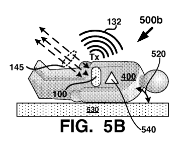
As one example of a motion event 520 that may generate motion signals
indicative of
harm to user 400, in FIG. 5B, the user 400 has fallen an impacted with a
structure 530 (e.g., the
ground) as denoted by arrows for 520 and the sensor system 140 has sensed 145
the motion
signals generated by the fall. The fall may also cause physiological events
540 or be caused by
physiological events 540 in the body of user 400. However, the present
discussion will focus on
motion event 520. Processing of the motion signals by processor 110 and
related algorithms
may determine that the motion signals are indicative of a motion event and
activate transmission
Tx 132 of user specific emergency medical data.
FIG. 5C depicts one example of a graph of a motion signal 500c over time
generated by
the motion related emergency event of FIG. 5A. Here, the one or more motion
signals generated
by sensors in sensor system 140 may be coupled with circuitry that converts
the motion signals
into a format that may be acted on by processor 110, such as converting an
analog motion signal
to a digital representation of the motion signal using an analog-to-digital
converter (ADC), for
example. Algorithms executing on processor 110 may analyze parameters of the
motion
signal(s) over time (e.g., acceleration in units of g-force vs. time in
seconds) to determine if the
signals are indicative of a motion event.
For example, in FIG. 5C, the algorithms may be configured to ignore any g-
force below
a threshold value of 531 as being related to a motion event. However, for
motion signals having
g-forces above the threshold value of 531, the algorithms may analyze the
motion signal 500c
over time to determine if the signal indicates a motion event. For example,
portions of the
motion signal 500c above the threshold value of 531 may include a rising edge
533, peak value
535, and falling edge 537. Parameters such as a time Atl between the rising
533 and falling 537
edges, the peak g-force value 535, and the slope and/or rise time of the
rising 533 and falling 537
edges, may be analyzed by the algorithms to determine if the motion signal
500c indicates a
motion event. Furthermore, the algorithms may analyze the motion signal 500c
for g-forces
below the threshold value, such as below dashed line 539 to determine if post
high g-force
motion signals are consistent with a motion event 520 that may cause harm to
user 400. As one
example, at a time At2 after the falling edge 537 the motion signal 500c is
below the threshold
value 531 for a longer period of time than Atl. Motion signal magnitudes
during time At2 may
be indicative of the user 400 being unconscious or otherwise immobile due to
injury caused by
the g-forces applied during Atl. Therefore analysis of the motion signal 500c
at time points
other than high g-force time points may be considered by the algorithms in
determining whether
or not a motion event has occurred. Moreover, motion signals generated by the
user activities
13
CA 02933169 2016-06-08
WO 2015/069946
PCT/US2014/064429
depicted in FIGS. 4B ¨ 4G, when analyzed by the algorithms may not result in
triggering a
motion event due to the repetitive motion signals generated (e.g., by running
400b, walking
400c, or rowing 400f) or the lack of or low magnitude of the motion signals
without a preceding
high g-force signal such as during Atl (e.g., standing 400d, sitting 400e, or
sleeping/resting/lying
down 400g).
Referring now to FIGS. 5D and 5E, FIG. 5D depicts one example of a
physiological
event 540 and FIG. 5E depicts one example of a graph of a physiological signal
500e over time
generated by the physiological event 540 of FIG. 5D. Here sensor system 140
may sense 145 a
change in physiological activity in body of user 400. Physiological signal
500e' may represent a
baseline signal 541 for a normal heart rate of user 400 as detected by
physiological and/or
motion sensors in sensor system 140. A time difference At3 between amplitude
peaks 541a and
541b may be larger (e.g., At3 > At4) than a time difference At4 between
amplitude peaks 543a
and 543b of physiological signal 500e' where there are more signal peaks per
unit of time than in
signal 500e'. Algorithms executing on processor 110 may analyze the
physiological signal 500e
and determine that it is indicative of heart and/or respiratory distress in
user 400 and trigger a
physiological event 540. Signal 500e' may be stored in data storage 120 as a
template, baseline,
table, or other data format and be used to compare against physiological
signals from the sensor
system 140. Signal 500e' may be actual captured physiological data from user
400.
In some examples, events 520 and 540 may occur at or near the same time and
one or
more algorithms executing on processor 110 may analyze the motion and
physiological signals
to generate a motion and/or physiological event. In some applications, motion
sensors may be
used to sense physiological activity such as heart beat, pulse, respiratory
rate, or other based on
motion in the body caused by the heart and/or lungs, for example. In other
examples,
physiological sensors may be used to sense and/or confirm a motion event, such
a change in
physiological activity caused by a motion event.
FIGS. 5F and 5G depict example of sensor signals related to body temperature
over time
and respiratory rate over time, respectively. In FIG. 5F, sensor system 140
may include sensors
that sense temperature including but not limited to skin temperature, body
temperature (e.g., core
temperature), ambient temperature, or any combination of the foregoing.
Physiological activity
in the body of user 400 may be caused by adverse temperatures or adverse
temperatures may be
indicative of harmful physiological activity. In either case, a physiological
event may be
triggered by a temperature range that is not healthy for the body. In FIG. 5F,
graph 500f depicts
a nominal range 545 of body temperatures over time (e.g., 30 min) that when
present in a
14
CA 02933169 2016-06-08
WO 2015/069946
PCT/US2014/064429
physiological signal analyzed by processor 110, may not trigger a
physiological event. However,
a higher temperature range such as hyperthermia range 547 (e.g., heat stroke
or fever) or lower
temperature range such as hypothermia range 549 (e.g., frost bite) when
present in a
physiological signal analyzed by processor 110, may trigger a physiological
event. Therefore,
physiological activity in the body of user 400 that may trigger a
physiological event may include
temperature as sensed by sensor system 140.
In FIG. 5G, graph 500g depicts a motion signal 544 over time (e.g., from
movement of
the user's body) and a physiological signal for respiratory rate 546. The two
signals (544, 546)
may be analyzed by processor 110 to determine if a discrepancy between the
signals (e.g., in
their respective waveforms over time) is indicative of a motion event,
physiological event, or
both. Therefore, an event may be triggered by different combinations of
signals from sensor
system 140, such as motion, temperature, physiological, or other signals
generated by sensor
system 140.
FIG. 6 depicts one example of a method 600 for a wearable personal emergency
event
transponder 100 as described herein. At a stage 601 signals (e.g., motion,
temperature,
physiological) from sensor system 140 may be analyzed (e.g., by processor 110
and algorithms
executing on the processor 110). At a stage 603 a determination may be made as
to whether or
not the analysis indicates an emergency. If an emergency is indicated, then a
YES branch may
be taken to a stage 605 where one or more events may be generated (e.g.,
motion event and/or
physiological event). If an emergency is not indicated, then a NO branch may
be taken and the
flow may return to another stage, such as the stage 601, for example. At a
stage 607, one or
more datum from user specific emergency medical data are selected based on the
one or more
events. For example, datum selected for a motion event may be different than
datum selected for
a physiological event. As another example, datum selected for a combination of
motion
physiological events may be different that datum selected for a motion only
event or a
physiological only event. At a stage 609 the selected datum are transmitted by
the transponder
100 (e.g., by communication interface 130 using RF system 135 and/or data port
138). At a
stage 611 a determination may be made as to whether or not the method 600 is
done (e.g., no
more events or signals to be analyzed). If done, then a YES branch may be
taken and the flow
may terminate. If not done, then a NO branch may be taken and the flow may
return to some
other stage, such as the stage 601, for example.
FIG. 7 depicts another example of a method 700 for a wearable personal
emergency
event transponder 100 as described herein. Method 700 is similar to method 600
with the
CA 02933169 2016-06-08
WO 2015/069946
PCT/US2014/064429
exception that at the stage 707, one or more datum from user contact data
and/or system data
(e.g., components of transponder 100) are selected based on the one or more
events. In some
applications, any combination of datum from user specific emergency medical
data, user contact
data, or system data may be selected based on the one or more events and
transmitted by the
transponder 100. Processor 110 may include multiple cores or compute engines
that may be
configure to process in parallel signals from sensor system 140. Motion
signals and
physiological signals may be processed by different algorithms executing on
different ones of the
multiple cores and may allow for parallel processing and/or simultaneous or
nearly simultaneous
processing of sensor signals. Methods 600 and 700, or sub-stages of those
methods may be
executed on different ones of the multiple cores. In some examples, the stage
607, 707, or both
may be implemented by a dispatch algorithm that is operative, based on the
type of event(s)
generated (e.g., at stages 605, 705, or both) to select one or more datum from
one or more of the
user specific emergency medical data, the contact data, the system data or for
the processor to
transmit (e.g., via RF system 135 and/or data port 138). The dispatch
algorithm may be included
in data storage 120. Dispatch algorithm may analyze the events generated and
determine which
datum are the most critical or pertinent to transmit based on the events. For
example, if the
emergency responders come to the aid of user 400, only a subset of the data
(e.g., see FIG. 8)
may be pertinent to the emergency responders to administer aid to the user
400. As another
example, if the user 400 is at a health care facility (e.g., a hospital), then
another subset of the
data may be useful, such as medical insurance information, date of birth,
name, social security
number, just to name a few. An application running on a device (e.g., a
smartphone) that
receives the transmission (e.g., Tx 132) may decide based on the
circumstances, which data to
harvest or parse out of the datum transmitted by transponder 100. Algorithms
that implement
methods 600 and/or 700 may be stored in data storage 120 and may comprise a
non-transitory
computer readable medium configured for execution on processor 110. Algorithms
that
implement methods 600 and/or 700 may be configured for execution on a DSP.
FIG. 8 depicts examples of one or more datum that may be transmitted by a
wearable
personal emergency event transponder 100 as described herein. Diagram 800
depicts a non-
limiting example of the data that may comprise user specific emergency medical
data 810, user
contact data 820, and system data 830. There may be multiple instances of data
810, 820, and
830 as denoted by 811, 821, and 831. The multiple instances may comprise the
data being
expressed in different languages (e.g., English, Mandarin, Spanish, French,
etc.), data being
expressed in different types of encryption, data being expressed in different
data structures or
16
CA 02933169 2016-06-08
WO 2015/069946
PCT/US2014/064429
formats (e.g., look up table, hash table, etc.), data being expressed in
formats or packets for
different communications protocols (e.g., Bluetooth, Bluetooth Low Energy,
Near Field
Communication (NFC), HackRF, USB-powered software-defined radio (SDR), etc.),
just to
name a few, for example. Data 810, 820, 830 and the multiple instances (811,
821, 831) may be
stored in data storage 120 (e.g., in Flash memory). Data not particularly
pertinent to user
specific emergency medical data 810 may be stored in the user contact data
820.
FIG. 9 depicts one example of a data port 138. Here, data port 138 may be a
USB port,
such as a micro or mini USB port, for example. An electrical connection 139
may be made with
the port 138 and another port 938 connected 963 with an external device 960
(e.g., a pad, tablet,
PC, or smartphone). A USB cable or the like may be used for the connection
139. The present
application is not limited to using a USB cable and USB connectors for port
138 and other
connectors and communication ports may be used. The datum transmitted by
communications
interface 130 may be communicated using the data port 138, the RF system 135,
or both.
Connection 139 and ports 138 and 938 may be used for data communication
between
transponder 100 and external device 960 and/or for supplying electrical power
to power system
150. External device 960 may detect (e.g., receive Rx 933) RF transmission Tx
132 from
transponder 100 when the two devices are at least within distance 970 of each
other or in direct
contact with each other. Distance 970 may represent a near field distance that
enables near field
communication between devices 100 and 960 and/or a distance sufficient for the
low power RF
signal transmitted Tx 132 by transponder 100 to be detected and reliably
received by a RF
system of external device 960.
External device 960 may be in data communication 991 with an external resource
990
(e.g., the Cloud or the Internet) via wireless communication (e.g., WiFi,
WiMAX, Bluetooth,
NFC, Ad Hoc WiFi, HackRF, USB-powered software-defined radio (SDR), Cellular,
2G, 3G,
4G, 5G) or wired communications link (e.g., Ethernet, LAN, etc.). External
resource 990 may be
in data communications 993 with other systems, such as data storage, servers,
and
communication networks, for example. External device 960 may include a display
970 that
presents a GUI 990 or other interface for communicating information to a user
of the external
device 960. An application (APP) 961 executing on a processor of device 960
may interpret and
display the datum transmitted by transponder 100. External device 960 may
communicate some
or all of datum received (e.g., Rx 933) to another system, such as resource
990 or other. For
example, device 960 may be carried and operated by an emergency responder and
at least a
portion of the datum may be passed on to a hospital or medical professional
via external resource
17
CA 02933169 2016-06-08
WO 2015/069946
PCT/US2014/064429
990. Data port 138 may be used to perform diagnostics on transponder 100, to
update or replace
data in data storage 120, to update or replace an operating system (OS) or
algorithms in
transponder 100, just to name a few. In some examples, RF system 135 may be
configured to
receive Rx 133 RF signals from the external device 960 or other RF source.
A radio in RF system 135 may be configured to transmit Tx 132 the one or more
datum
(see FIG. 8) using Near Field Communication (NFC) or other close range (e.g.,
typically lm or
less) RF communications protocol. The one or more datum may be wirelessly
transmitted Tx
132 using as at least one NFC format including but not limited to: a Record
Type Definition
(RTD); a NFC Tag; a Smart Poster Record Type Definition; a NFC Data Exchange
Format
(NDEF); just to name a few. Algorithms in data storage 120 and/or associated
with methods 600
and/or 700 may be configured to implement one or more NFC formats. The NFC
format may
include one or more of a Uniform Resource Name (URN), a Uniform Resource
Indicator (URI)
or a Uniform Resource Locator (URL).
The radio may configured for Bluetooth Low Energy (BTLE) and the one or more
datum
may be wirelessly transmitted Tx 132 using BTLE. The one or more datum may be
encoded as a
message in one or more advertising channels per the BTLE specification or an
adaptation of the
BTLE specification, for example. As one example, the one or more datum may be
encoded in a
device ID or device ID profile. As another example, the one or more datum may
be encoded in a
custom defined Bluetooth (BT) profile configured to be decoded by an
application (e.g., APP
961) executing on another device (e.g., device 960) or on another BTLE device.
On the other hand, the radio may be configured for wireless communication
using
Bluetooth (BT) and the one or more datum may be wirelessly transmitted Tx 132
using one or
more BT protocols, for example. As one example, the one or more datum may be
encoded as an
object in a BT Object Exchange (OBEX). As another example, the one or more
datum may be
encoded in a device ID or device ID profile. Other BT profiles that may be
used transponder 100
include but are not limited to: proximity profile (PXP) ; health device
profile (HDP) ; file
transfer profile (FTP) ; generic access profile (GAP) ; device ID profile
(DIP) ; basic imaging
profile (BIP) ; message access profile (MAP) ; and phone book access profile
(PBA , PBAP),
just to name a few. Wireless communication using BT may include BT SMART for
wireless
synching, and BT 4.0 for low power consumption and/or automatically synching
with external
wireless devices. The foregoing are non-limiting examples of wireless
communication protocols
that may be used by transponder 100 and other protocols, standard, customized,
or proprietary
may be used.
18
CA 02933169 2016-06-08
WO 2015/069946
PCT/US2014/064429
The systems, devices, apparatus and methods of the foregoing examples may be
embodied and/or implemented at least in part as a machine configured to
receive a non-transitory
computer-readable medium storing computer-readable instructions. The
instructions may be
executed by computer-executable components preferably integrated with the
application, server,
network, website, web browser, hardware/firmware/software elements of a user
computer or
electronic device, or any suitable combination thereof. Other systems and
methods of the
embodiment may be embodied and/or implemented at least in part as a machine
configured to
receive a non-transitory computer-readable medium storing computer-readable
instructions. The
instructions are preferably executed by computer-executable components
preferably integrated
by computer-executable components preferably integrated with apparatuses and
networks of the
type described above. The non-transitory computer-readable medium may be
stored on any
suitable computer readable media such as RAMs, ROMs, Flash memory, EEPROMs,
optical
devices (CD, DVD or Blu-Ray), hard drives (HD), solid state drives (SSD),
floppy drives, or any
suitable device. The computer-executable component may preferably be a
processor but any
suitable dedicated hardware device may (alternatively or additionally) execute
the instructions.
As a person skilled in the art will recognize from the previous detailed
description and
from the drawing FIGS. and claims set forth below, modifications and changes
may be made to
the embodiments of the present application without departing from the scope of
this present
application as defined in the following claims.
Although the foregoing examples have been described in some detail for
purposes of
clarity of understanding, the above-described inventive techniques are not
limited to the details
provided. There are many alternative ways of implementing the above-described
techniques or
the present application. The disclosed examples are illustrative and not
restrictive.
19