Note: Descriptions are shown in the official language in which they were submitted.
CA 02933450 2016-06-10
WO 2015/106352
PCT/CA2015/050023
1
OPTICALLY VARIABLE PRINTED FEATURE
FOR SECURITY DOCUMENTS
FIELD OF THE INVENTION
[0001] The invention relates generally to a security feature for printed
products. In
particular, the present invention provides a printed product and method of
image
layering to produce an optically variable, i.e. kinetic, "moving image"
effect, for use in
printed security documents including but not limited to driver's licenses,
passports,
and banknotes.
SUMMARY OF THE INVENTION
[0002] The present invention provides an optically variable printed feature
for
security documents providing a kinetic appearance of a moving image,
optionally
with colour shifting, as one views the feature from different angles.
[0003] According to one aspect of the invention, a security document comprises
a
substrate of which at least a part comprises an optically variable printed
feature and
is at least semi-transparent over a thickness from a front surface to a back
surface of
the substrate. The optically variable printed feature comprises a plurality of
substantially parallel lines and/or line segments printed on the front surface
and a
corresponding plurality of substantially parallel lines and/or line segments
printed on
the back surface. The lines and/or line segments on the back surface relative
to the
lines and/or line segments on the front surface are located in at least near
perfect
registration to form sets of lines and/or line segments, each set comprising a
predetermined pattern of at least one of the front surface printed lines
and/or line
segments and at least one of the back surface printed lines and/or line
segments.
The thickness of the substrate relative to the line widths is selected such
that the
optically variable printed feature becomes visible upon viewing the substrate
part
from one angle to a different angle above the front surface.
[0004] According to another aspect of the invention a method of making a
security
document having an optically variable security feature is provided. A
plurality of
CA 02933450 2016-06-10
WO 2015/106352
PCT/CA2015/050023
2
substantially parallel lines and/or line segments are printed on a front
surface of at
least a part of a substrate which is at least semi-transparent over a
thickness
extending from the front surface to a back surface of the substrate part. A
corresponding plurality of substantially parallel lines and/or line segments
are printed
on the back surface of the substrate part. The lines and/or line segments on
the
back surface are located in at least near perfect registration relative to the
lines
and/or line segments on the front surface to form sets of lines and/or line
segments,
wherein each set comprises a predetermined pattern of at least one of the
front
surface printed lines and/or line segments and at least one of the back
surface
printed lines and/or line segments. The line widths and the thickness of the
substrate part relative to the line widths are selected so that the optically
variable
printed feature becomes visible when the substrate part is viewed from one
angle to
a different angle above the front surface.
[0005] The optically variable printed feature of the security document
comprises an
image defined by a plurality of image pixels. Each image pixel comprises a
predetermined area of the substrate extending from the front surface to the
back
surface of the substrate, and one the set of the predetermined pattern of
lines and/or
line segments.
[0006] The line(s) and/or line segments of the predetermined pattern may
comprise
different colours whereby the optically variable feature comprises colour
shifting.
[0007] In an exemplary embodiment the predetermined pattern of printed lines
and/or
line segments comprise at least a 2 x 2 pattern comprising two of the front
surface
printed lines and/or line segments and two of the back surface printed lines
and/or
line segments, each the printed line comprising a different colour, the
optically
variable feature comprising colour shifting.
[0008] Preferably, the front surface printed lines and/or line segments are at
least
semi-transparent. The front surface and back surface printed lines and/or line
segments may be angled up to 2 degrees relative to each other. The lines
and/or
line segments have a width of between 30-90 pm and the thickness of the
substrate
is between 25-850 pm.
CA 02933450 2016-06-10
WO 2015/106352
PCT/CA2015/050023
3
[0009] The substrate comprising the front surface and back surface printed
lines
and/or line segments may be provided as an intermediary layer located in a
composite substrate comprising multiple layers.
[00010] A layer of lenticular lenses configured and arranged for enhancing the
optically variable printed feature may be provided.
[00011] Preferably, the front surface and the back surface printed lines
and/or line
segments are printed simultaneously using a Giori Simultan press.
[00012] Further features and advantages of the invention will be apparent from
the
detailed description which follows together with the accompanying drawings.
BRIEF DESCRIPTION OF THE DRAWINGS
[00013] A better understanding of the invention will be obtained by
considering the
detailed description below, with reference to the following drawings.
[00014] Figure 1 is a side angle, enlarged perspective view of a part of an
exemplary security document substrate comprising an optically variable printed
feature depicting a maple leaf image in accordance with the invention and a
lens
layer there over for enhancing and magnifying the optical effect.
[00015] Figure 2 is a side angle, enlarged perspective view of a part of a
different
exemplary security document substrate comprising an optically variable printed
feature which includes a phase shifted image of a maple leaf in accordance
with the
invention (a lens layer is not included in this embodiment).
[00016] Figure 3 is a side view of an expanded part of another exemplary
security
document substrate comprising an optically variable printed feature,
illustrating a
visual effect when viewed from different side angles above the substrate when
light
impinges upon a substrate surface.
[00017] Figure 4 is an exploded view of an exemplary security document
substrate
comprising multiple substrate layers that are combined to form the security
CA 02933450 2016-06-10
WO 2015/106352
PCT/CA2015/050023
4
document substrate, wherein the second substrate layer from the front
comprises an
optically variable printed feature in accordance with the invention.
[00018] Figure 5 is an enlarged side view of a part of a further exemplary
security
document substrate comprising an optically variable printed feature in
accordance
with the invention and a front lens layer there over, showing sets of four
print lines of
different colours below each lens of the lens layer, each set having two lines
of
different colours printed on the front surface and two lines of different
colours printed
between them on the back surface.
[00019] Figure 6 is a side angle perspective view of an exemplary banknote in
a
folded over configuration, the lower part of the banknote comprising an
optically
variable printed feature in accordance with the invention and the upper folded
over
part of the banknote comprising a lens for use to improve the visibility of
the optically
variable feature, and an exploded view "A" of the part of the substrate
comprising the
optically variable printed feature.
DESCRIPTION OF EMBODIMENTS OF THE INVENTION
[00020] The invention provides a product in the form of a security document,
including but not limited to driver's licenses, passports, banknotes and other
secure
instruments, comprising an optically variable feature 10 printed on a
transparent or
semi-transparent substrate 20 of the product, and a method for making the
product.
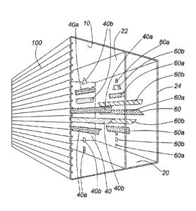
[00021] Exemplary embodiments of the product are illustrated by the drawings
of
which Figure 1 shows a part of an exemplary security document substrate 20
having
an optically variable printed feature 10 comprising printed front surface
lines 40 and
printed back surface lines 60 each set of lines 40, 60 forming a part of a
visible
image, being a maple leaf in this example, and having a lens layer 100 there
over for
magnifying the variable optical effect of feature 10. As shown, the lines 60
printed
on the back surface 24 of the substrate 20 are located directly below the
spaces
between the lines 40 on the front surface 22 such that, if combined together
in a
single plane, there would be no spaces (or smaller spaces) between the lines
40, 60
and, together, the lines 40, 60 would form the whole of the distinct image.
The
CA 02933450 2016-06-10
WO 2015/106352
PCT/CA2015/050023
distance between the front and back surface lines 40, 60 corresponding to the
thickness of the substrate 20, relative to the widths of those lines 40, 60,
produces a
parallax effect which causes the optically variable printed feature 10, being
an
appearance of movement of the visible image, to become visible to a viewer
upon
viewing the substrate from different angles above the front surface 22.
[00022] The printed lines 40 and 60 include a very large number of very thin,
precisely printed lines, arranged according any one of different predetermined
patterns on a pixel-by-pixel basis. Due to their thinness, in the order of
tens of
microns, the discrete lines are not apparent when one views the feature 10
and,
instead, the viewer sees a macro-image formed by the combination of the front
and
back printed line patterns 40, 60 (the lines shown in the drawing are depicted
in an
exaggerated large form for purposes of illustration only). The printed lines
40 and 60
may be of different colours as shown in this example of which lines 40a are
blue,
lines 40b are red, lines 60a are green and lines 60b are yellow, in which case
the
optical variable feature 10 includes a visible colour shifting effect when
viewed from
different angles. For example, when one views the printed feature 10 at an
angle of
-45 degrees from the vertical the image of the maple leaf appears to the
viewer to be
blue, but then when the viewing angle is moved to +45 degrees from the
vertical the
apparent colour of the maple leaf image, to the viewer, changes from blue to
red.
[00023] As will be understood by the skilled reader, while continuous printed
lines
are depicted in the drawings of the exemplary embodiments herein to illustrate
the
optically variable feature of the invention, it is not necessary that
continuous lines be
used. Rather, line segments, including dashes, dots and other elements
providing in
combination an appearance of a line, may be printed on the substrate as
described
instead of continuous lines. Throughout this description the term "lines" is
intended
to refer to both continuous lines and such line segments.
[00024] Figure 2 shows a part of another exemplary security document substrate
20
having a different optically variable printed feature 10 comprising printed
front 40 and
back 60 surface lines, coloured as in the example of Figure 1, of which the
front lines
40 (only) form a distinct embedded image (viz, in this example a maple leaf)
and
excluding the lens layer 100 which, though preferred to enhance the visual
effect of
CA 02933450 2016-06-10
WO 2015/106352
PCT/CA2015/050023
6
the optical variable feature 10, is not required in order for the optical
effect of the
feature 10 to be visible.
[00025] To produce the optically variable feature 10 each pixel of the image
of the
feature must include a set of front and back printed lines 40 and 60. The
front and
back printed lines must be printed in perfect or near perfect registration in
order to
ensure they fall within the area of one image pixel and thereby define the
pixel
image. Within each pixel, the printed lines are parallel or substantially
(i.e. near)
parallel, with parallel lines producing a greater optical effect (e.g. if
different coloured
lines are use, the strongest colour shift effect). If non-parallel and too
much tilt is
present, an undesirable Moir_ effect will be produced. Non-parallel lines,
tilting
relative to each other up to 1 or 2 degrees may produce an acceptable
optically
variable feature depending upon the application.
[00026] The part of the substrate 20 comprising the optically variable feature
10 is
transparent or at least semi-transparent over the thickness of the substrate
from the
front surface 22 to the back surface 24 so that light impinging on those
surfaces
produces varying levels of absorbed and reflected light depending on the
impinged
surface whereby, in the area of the printed optically variable feature 10,
these levels
are determined by the grey scale level or colour of the printed lines 40, 60.
Figure 3
illustrates a reflected light effect of light (L) passing through the front
surface spaces
(i.e. between print lines 40) onto the back print lines 60, impinging on the
printed
substrate surfaces, to appear as lines 1 and 3 when viewed from different side
angles ( e from the vertical) above the substrate and produce the optically
variable
visual effect.
[00027] In these embodiments, the inks used to print at least the front
surface lines
40 are semi-transparent so light will pass from at least the front of the
printed feature
though both the ink of the printed lines 40 and the spaces between them, the
light
passing though the ink being filtered in a manner which depends on the color
of the
ink. The filtered light interacts with the printed lines 60 on the back
surface 22 and
some gets absorbed, some reflects back and gets transmitted. Where the feature
10
is incorporated into a window portion of a product, being substantially
transparent
throughout, light will also from the back of the printed feature 10. The
differing
CA 02933450 2016-06-10
WO 2015/106352
PCT/CA2015/050023
7
degrees of absorption/reflection/transmission, depending on the grey scale
level or
colour of the printed lines 40, 60 and the angle from which the printed
feature 10 is
viewed, produces a visible optically variable (i.e. kinetic or moving image)
effect
when the substrate is viewed from one angle to another, and this which
includes a
color shifting effect where the lines 40, 60 are of different colours.
[00028] The substrate 20 is comprised of a material that is either transparent
or
semi-transparent and is capable of accepting printing such as polycarbonate,
polyester, polypropylene, and other similar materials. It may be formed as a
single
layer or as multiple layers, as illustrated by Figure 4 which shows an
exploded view
of an exemplary security document substrate 20 comprising multiple substrate
layers
that are combined to form the security document substrate 20. In this example,
the
second substrate layer 20a from the front comprises an optically variable
printed
feature 10, comprising back and front print lines 40, 60, in accordance with
the
invention. Substrate layer 20a is a non-laser-engravable (nLE) material of 250
pm
thickness, while the other substrate layers vary in thickness from 100 ¨ 150
pm and
each of the outer layers is laser-engravable (LE). In at least the area of the
optically
variable feature 10 all of the layers making up the substrate 20, must be
substantially
transparent (i.e. transparent or semi-transparent).
[00029] The visual effect of the optically variable feature 10 may be enhanced
through the addition of a lenticular lens layer 100 above the substrate layer
20 on
which the lines 40, 60 of the optically variable feature 10 are printed, as
illustrated by
Figures 1 and 5. Such a lens layer 100 is comprised of lenticular lenses or
equipped
with lenticular lenses on its upper surface. As shown in Figure 5, each of the
lenses
110 is oriented parallel to the printed lines 40, 60. To obtain an optimal
visual effect,
the distance between the upper surface of the lens layer 100 and the center of
the
substrate layer 20 should be approximately equal to the focal length of the
lenticular
lenses.
[00030] The embodiment of Figure 5 uses a preferred 2x2 line pattern whereby
each image pixel comprises 2 front lines 40a,b and 2 back lines 60a,b. Four
different colours are used for each set of pixel lines, namely, line 40a is
blue, line
40b is red, line 60a is green and line 60b is yellow. The width of each line
40a,b,
CA 02933450 2016-06-10
WO 2015/106352
PCT/CA2015/050023
8
60a,b is 90 pm so the pixel size is 360 pm (i.e. 4 x 90 pm) and all four lines
must be
printed, including any desired adjustment to thickness such as to incorporate
a
phase shifted image (e.g. the maple leaf in Figure 2) and/or angle, within
that pixel
size on the substrate. As illustrated, each lens 100 has a diameter
corresponding to
the width of each set of 4 lines i.e. to each image pixel.
[00031] As stated, the optically variable feature 10 depicted in each of
Figures 1, 2,
and 6 comprises a number of sets of four lines of different colours, each
arranged
in a predetermined pattern whereby two of the line colours are printed on the
front
surface 22 of the substrate 20 with the other two line colours are printed on
the back
surface 24 of the substrate 20. For each set of four print lines, the lines
printed on
the front surface must be parallel to each other and the lines printed on the
back
surface must also be parallel to each other. The lines printed on the front
surface
are not required to be parallel to the sets of lines printed on the back
surface and
may be angled at 1 or 2 degrees, or they may be parallel. The two front
surface
lines and the two back surface lines of each set of four coloured lines must
be
printed in perfect or near perfect registration so that they are perfectly
spaced
relative to each other. As such these line sets of four lines there may be
printed
according to either of two predetermined patterns, namely, either the 2 sets
of lines
are butted side by side or they are evenly spaced. That is, on the front
surface a
pattern of line, line, space, space is printed, or a pattern of line, space,
line, space
and, on the back surface a pattern of space, space, line, line is printed, or
a pattern
of space, line, space, line, respectively.
[00032] The transparent or semi-transparent substrate layer 20 has a thickness
in
the range of 25 to 850 pm. To obtain an optimal visual effect, the width of
the lines
40, 60 printed on both the upper and the lower surfaces should be the same.
However, while not optimal some kinetic visual effect will be obtained using
lines of
different widths, the back lines 60 of the embodiment shown by Figure 3
illustrating
an example of such different widths, the back lines 60 having a smaller width
than
the front lines 40. While the width of the lines is limited only by the size
of the
medium, it has been found that using a line width between 30 to 90 pm produces
a
high quality visual effect, with a strong flip effect (colour shift) where
different front
and back line colours are used, while at the same time keeping the visibility
of the
CA 02933450 2016-06-10
WO 2015/106352
PCT/CA2015/050023
9
line arrangement (as opposed to the macro image created by the line
combination as
a whole). If desired, lines with angles of 1 or 2 degrees, preferably between
0 ¨
1.124 may be used to increase the rainbow, or sweeping, effect of the feature
10.
To do so, either of the front surface lines, or back surface lines, may be
printed at
such an angle relative to the other line.
[00033] Various technologies may be utilized in the printing of the lines 40,
60. For
the illustrated embodiments a Giori Simultan press was used to print the front
surface and back surface lines simultaneously with very high resolution and
having a
width as small as 20 pm. This type of press, provided by the manufacturers
KOMORI Corporation (i.e. its LT-83211A product) and KBA-NotaSys SA (i.e. its
Simultan product), is able to print as many as four different colours of lines
with
perfect registration of the front and back printing on a pixel-by-pixel basis.
Referring
to the embodiment of Figure 5, having a 2 x 2 print pattern of four print
lines per
pixel, this means that for each image pixel the two back surface lines 60
is/are
precisely located directly below the space between the two front surface lines
40.
[00034] Any type of ink may be utilized for the printing of the lines 40, 60
including
invisible fluorescent inks. However, an optimal kinetic effect results when
visible,
semi-transparent ink is used whereby the transparency of the printed lines
acts as
filter for light. The best results are typically achieved through the use of
visible inks
mostly made up of organic pigments. Inks made up of organic pigments usually
have better transparency (lower optical density) and produce a better color
shifting
effect. However, metallic pigment having a high optical density may also
produce an
acceptable kinetic effect depending upon the image design and application.
[00035] As a result of many tests run by the applicant to test embodiments of
the
printed optical variable feature of the invention a Giori Simultan Press was
chosen
for printing the feature lines because it enables the back surface lines 60 to
be
printed in perfect registration with the front surface lines 40. Due to the
mechanical
nature of a normal offset press, if such a press is used to print the front
surface and
back surface lines over two passes an undesirable pixel migration may occur
whereby the printing on the second pass migrates towards the next pixel. Since
the
CA 02933450 2016-06-10
WO 2015/106352
PCT/CA2015/050023
Giori Simultan type, common blanket, presses are only available for security
printers,
counterfeiting will be difficult.
[00036] Various implementations of the invention included the following
specifications:
Press: Giori Simultan offset press
Plates: (Dry plates)
P1SD1 ¨ Mounted at the front of the press
P2SD1 ¨ Mounted at the front of the press
P1SD2 ¨ Mounted at the back of the press
P2SD2 ¨ Mounted at the back of the press
Line work: (Thicker and thinner background/ Regular and thicker relief)
1 front surface line/1 back surface line (1 x 1)
1 front surface line/2 back surface lines (1 x 2)
2 front surface lines/2 back surface line (2 x 2)
2/2 Even /Odd
2/2 Line Pair
2/2 Criss Cross
Concentric Circles
Substrates:
Bayer Clear 100um LE (14179)
Bayer Clear 150um LE (14180)
Sabic Clear 250um nLE (15711)
Sabic Clear 375um nLE (15254)
Inks:
Metallic Inks Invisible Fluorescent Inks
Silver 877 Invisible Blue 9455
Gold 871 Invisible Red 9025
Invisible Yellow 9960
CA 02933450 2016-06-10
WO 2015/106352
PCT/CA2015/050023
11
Invisible Green 9475
Standard Inks Standard Inks with 10% TiO2
5853 Blue 5853 Blue + 10% TiO2
Red 1853 Red 1853 + 10% TiO2
Yellow 3853 Yellow 3853 + 10% TiO2
Green 4853 Green 4853 + 10% TiO2
[00037] Tests conducted by the applicant using standard lithographic inks,
with and
without Ti02, printed over 250 pm polycarbonate substrate sheets showed strong
kinetic effects. The tests also demonstrated that the greater the distance
between
the front and back surface lines (i.e. the greater the thickness of the
substrate layer
upon which they are printed) the stronger the parallax effect and, in turn,
the greater
the kinetic effect and, where different colours are used for the lines of the
two print
levels, the better the colour shifting effect. While many combinations of line
arrangements achieve the desired result, arrangements of at least 2 x 2
parallel lines
and odd/even lines were found to provide an optimal color shift. Lines of 30
to 90
pm width provide a strong flip effect while at the same time keeping the
visibility of
the lines minimal. The kinetic color shifting effect can also be further
enhanced by
utilizing lighter back surface lines, as compared to the use of a darker
lines.
[00038] The optically variable feature 10 of the invention can also be
utilized to
enhance the security of banknotes as illustrated by the embodiment shown in
Figure
6. In this embodiment, a banknote 200 includes a transparent and/or semi-
transparent window, shown by the exploded view "A" included in Figure 6
comprising
a transparent or semi-transparent substrate 20. The front 40 and back 60
surface
print lines of the feature 10 are applied to the substrate 10 by either the
banknote
printer or the substrate manufacturer. The registration between the front set
of lines
40 to the back set of lines 60 should be perfect or near perfect to avoid an
undesirable Moir_ effect. For this banknote application, applying a lens layer
100
directly over the printed line pattern of the feature 10, although possible,
may be too
costly so, instead, a lenticular lens layer 100 is provided on a second
transparent or
semi-transparent window by the substrate manufacturer during the process of
manufacturing the substrate. In use, to authenticate the feature, the user
folds over
CA 02933450 2016-06-10
WO 2015/106352
PCT/CA2015/050023
12
the banknote as shown by Figure 6 so that the lenses of the lens layer 100 are
placed over and in front of the printed optically variable feature 10, to
verify the
genuineness of the banknote 200 by determining a kinetic effect, and colour
shifting
effect if the feature 10 uses colour, upon viewing the feature 10 from
different angles.
[00039] As will be recognized by persons skilled in the art, many other
combinations and materials will yield similar results and are within the scope
of this
invention, and the invention is not limited to any particular substrate (which
may be
of various thicknesses an appropriately selected by the skilled person for a
given
application), combination or arrangement of print lines (which may include
embedded images of any form) or type of ink and/or ink colours.
[00040] Although various exemplary embodiments of the invention have been
disclosed, it is to be understood that various changes and modifications can
be
made to achieve the invention without departing from the scope thereof, which
is
defined by the appended claims.