Note: Descriptions are shown in the official language in which they were submitted.
CA 02933675 2016-06-13
1
Description
Leakage monitoring system for space-enclosing objects
and coupling regions located therebetween and related method
The invention relates to a leakage monitoring system for space-enclosing
objects, in
particular made of plastics material, such as pipes, hoses or containers,
comprising an
exterior wall which separates a medium guided therein from the external
environment,
the system having at least one electrically conductive element acting as a
leakage
sensor, which is mounted on the exterior wall or integrated therein. In a
specific
embodiment, coupling regions or transition regions between such media-guiding
enclosures, in particular pipes or hoses, which can be combined in any desired
manner
and sequence, are monitored in a targeted manner. The invention further
relates to a
corresponding method for preventative and/or direct leakage monitoring.
In many pipelines, hoses or containers of industrial facilities, in particular
in nuclear
power facilities, liquids or gases (generally referred to as fluids) are
guided which are
harmful or hazardous to the environment. This makes it necessary to monitor
such fluid-
guiding or media-enclosing objects for leakages.
For this purpose, different types of sensors and monitoring methods have been
developed. For example, it is known to monitor the integrity of a pipe wall
using
electrical conductors embedded therein. In this context, EP 2 287 587 A2
discloses a
system in which a monitoring problem is solved based on the action of an
electrical
short circuit between two conductors incorporated in a pipe.
However, a system of this type is neither specifically designed nor sensitive
enough to
reliably determine even the smallest leakages of fluids, for instance at
joints of a pipe
wall or container wall, or through micropores.
The problem addressed by the present invention is that of providing a leakage
monitoring system of the type mentioned at the outset which makes simple and
reliable
monitoring of the smallest leakages possible, even for extensive wall regions,
and
specifically in as universal a manner as possible for different types of
fluids or media. In
particular, the aim is for preventative monitoring which responds even before
an actual
CA 02933675 2016-06-13
2
incipient leakage, i.e. when a leakage is imminent. A corresponding method
will also be
provided.
In relation to the device, the problem is solved according to the invention by
the features
of claim 1 and, in relation the method, by the features of claim 9.
Accordingly, the electrically conductive element which is mounted on the
exterior wall or
integrated therein is a component of a measuring bridge, which has a device
for
evaluating the bridge voltage and which is powered by means of a voltage
source
having an operating voltage, which contains both AC voltage components and DC
voltage components. In this case, the electrically conductive or generally
electrically
active element can have any spatial shape and structure appropriate for the
monitoring
task, in particular can form a sensor layer, and is also described in short as
a conductor
in the following for reasons of simplification.
The invention is based on at least one electrically active sensor (e.g. a
conductive
network system or grid or an arrangement of wires, but also elements made of
conductive or semi-conductive material in another form) being incorporated in
the wall
material or shell material between the external face facing away from the
medium and
the medium-guiding internal face. The arrangement of the sensor material is
assumed
as given. Any material which provides a sufficiently large change in one of
their
electrical parameters - in particular electrical resistance, capacitance
and/or inductance
- in the event of a leakage can be used as the sensor material.
In addition, it is not an actual leakage that is detected, but preferably
preventative or
prognostic monitoring is possible in the sense that even a change to the
material or
structure of the wall material prior to a leakage, for instance owing to
damage, wear,
erosion and the like, leads to a change in electrical parameters, which change
is
measured and optionally used to trigger an alarm, even before a leakage
actually takes
place. Within the context of this description, where leakage monitoring is
referred to for
reasons of simplification, it always relates to preventative monitoring of
this kind of an
impending or directly imminent leakage. Terms such as "leakage sensor" and the
like
are to be understood similarly.
CA 02933675 2016-06-13
3
The invention is based on the concept that the sensor implemented in this
manner is
intended to be included in the measurements in an AC voltage measuring bridge.
The
complex electrical resistance (impedance) is thus assessed by measuring and
evaluating the bridge voltage, in particular with regard to frequency,
magnitude and
phase position. This takes into consideration both ohmic and capacitive and/or
inductive
changes in the arrangement caused by a material change resulting from the
leakage or
preceding it.
The actual sensor is thus an element of the measuring bridge that is
integrated in the
object to be monitored, for instance in a pipe wall / hose wall / container
wall. The other
electrical/electronic components which complete the arrangement to form a
complete
measuring bridge are implemented in a separate measurement circuit. The
measurement arrangement can be attached to the test object in its immediate
proximity
or remotely.
It is essential that the measuring bridge is powered both by DC voltage and by
AC
voltage of a specific, known frequency. The design of the circuit makes it
possible for
the smallest changes in electrical parameters (caused by the material change
or shape
change leading to a leakage) to lead to both a large change in amplitude and a
change
in signal shape resulting from the superimposition of DC voltage components
and AC
voltage components. This increases the evaluation and assessment reliability
of the
generated signal with respect to interference and to the signal in the
operating state.
The evaluation unit preferably comprises an electronic processing unit for the
measurement signal. In a simple case, said unit can be merely an indicator
device for
the measurement signal but can naturally also have even more and/or
alternative
components. For example, an electronic memory unit for the measurement signal
can
be provided, for instance in the form of a ring memory and/or non-volatile
memory.
Furthermore, a diagnostic module is advantageous, which, for example by means
of
threshold values and/or relevant evaluation algorithms, automatically detects
sudden
and/or long-term changes in the measurement signal, which indicate an
impending/imminent/currently incipient or already occurring leakage, and/or
classifies
said changes into different groups of features and in particular uses said
changes to
trigger an alarm.
CA 02933675 2016-06-13
4
The frequency of the AC voltage is preferably switchable or covers a specific
frequency
range. The switching of the frequency is used in particular when, during a
plausibility
check of the bridge detuning, specific criteria do not lead to any conclusive
assessment
of the signal.
The measuring circuit is preferably band-limited, i.e. it functions only in a
low frequency
range around the base frequency. This design is also retained if the frequency
is
switched as described above.
In accordance with the measuring principle, the wall material or shell
material of the
object to be monitored, for instance of the pipe/hose/container, is preferably
non-
electrically conductive, in particular non-metallic. Instead, the method is
suitable in
particular for preventative and direct leakage monitoring of medium-adjoining
plastics
components (plastics plates, pipes, hoses, containers). However, it is also
possible to
monitor, in the manner described, objects which have a metal exterior wall or
objects
which have an existent metal-non-metal composite structure, the metal
components or
parts thereof forming the elements acting as sensors, which are coupled into
the
measuring bridge.
In monitoring a plurality of objects using a plurality of sensors and
associated measuring
bridges, each monitored object (this can be e.g. a pipe section or a sub-
surface of a
larger wall surface) can advantageously be assigned a distinct individual
identifier by
means of which it can be identified. The measurement results and assessment
thereof
can thus be assigned to this identifier. It is thereby possible to pinpoint
the location of
the change in or damage to the wall material, put simply the leakage location,
which
causes leakage at a later stage.
In general terms, the described monitoring device can be included in a system
which is
able to provide location information with regard to the damage. This is
possible in
particular if the sensor element or the electrode of the measurement circuit
are assigned
one-to-one to a signal-processing unit, which in turn links the measured
signal to a
system-wide one-to-one identification.
It is also possible to divide an arrangement of the monitoring locations into
individual
sections, which are connected to a central processing apparatus. The original
and the
CA 02933675 2016-06-13
assessed measurement signal can be transmitted via a bus system to the central
processing apparatus (e.g. host computer).
By means of the measuring arrangement according to the invention, vibrations
or shock
in space-enclosing objects such as pipes, hoses or containers and/or coupling
regions
located therebetween can also be monitored. This monitoring can take place in
the
described manner by impedance measurement in the region of the exterior wall
of the
monitored object and by evaluation of the temporal changes. In other words, in
evaluating temporal impedance changes, conclusions are drawn on movements or
accelerations of pipe segments or other segments causing such changes.
Alternatively
or additionally, determined acceleration sensors, in particular in chip form,
can be
arranged in/on the object, which sensors directly provide corresponding
acceleration
measurement values.
Vibration or shock monitoring of this kind can have in particular one or more
of the
following objectives, exemplified here using the example of a pipeline:
a) Intrusion detection: monitoring a pipeline for mechanical manipulations,
e.g.
targeted tapping or by vandalism, but also detecting building work in the
vicinity which
would threaten the safety or integrity of the pipeline.
b) Seismic monitoring: seismic activities can be detected in the entire
pipeline. The
epicentre can be located by locating the measuring point. The measurement data
are
stored and evaluated for the aging management.
c) Operating vibrations: vibrations which result during operation are
detected and
recorded. Short-term events such as cavitation are detected. The detected
measurement data are likewise centrally stored and evaluated for the aging
management.
In order to be able to check the condition of the measuring arrangement,
reference
circuits are provided which can generate a known signal and which input this
signal into
the measuring bridge instead of the sensor signal when in the test or checking
mode,
and optionally for the purposes of calibration.
CA 02933675 2016-06-13
6
The arrangement can also be provided with moisture sensors and/or temperature
sensors and/or other sensors (for instance acceleration sensors) for detecting
the
environmental conditions or specific material properties. Further statistical
or
measurement assessments can thus then be carried out.
In this context, the temperature measurement is of particular interest.
Similarly to the
vibration monitoring, preferably at least one temperature sensor is
implemented/installed on each monitoring module or pipe segment in question.
The
temperature sensor can be integrated on/at the inner face or the outer face of
the fluid-
guiding enclosure or also in the wall.
Temperature measurement values are preferably read cyclically and stored
centrally in
a database. There are two advantageous basic types of evaluation:
A posteriori: For the pre-leakage alarm, the stored temperature data are
investigated
and it is identified whether material fatigue caused by temperature has
occurred.
A priori: By
considering the temperature data, a reliable prognosis can be made
for discrete pipe segments with respect to the maximum service life /
operational life expectation. A recommendation for replacement to the
operator is derived therefrom.
Generally, preferably all the measurement data from pre-leakage monitoring,
vibration
monitoring and temperature monitoring are stored in a database. All the data
can be
interlinked. By suitable weighting of the individual influencing factors, a
trend can be
calculated for each monitoring module or pipe segment in question (aging
management).
The measurement arrangement can be networked and exchange information with
other
locations via a data network, for example in order to stabilise the sensor
signals with
respect to climatic influences. It is also possible to externally check the
measurement
arrangement, adjust the parameters thereof or retrieve information therefrom.
CA 02933675 2016-06-13
7
The arrangement and method preferably lead to the generation of warnings or
alarms or
of information which can be used to trigger an alarm. It is possible to
monitor the object
in question continuously or cyclically.
So far, the focus of the description has been on the monitoring of planar
regions, in
particular the leakage monitoring of pipe bodies. Similarly, coupling regions
and
transition regions in pipe/hose/container connections and similar object
connections can
also be monitored in a targeted manner for a change in or damage to the
coupling gap
between the two interconnected components leading to or encouraging leakage.
In this
case too, a mainly electrically non-conductive characteristic of the pipe wall
material, at
least in the coupling region, is preferred.
In this case, the preferred arrangement of the electrical conductor forming
the leakage
sensor substantially comprises one or more conductive rings which completely
enclose
the connection location and form the electrodes of an electrical measurement
circuit.
The rings can be in particular electrically conductive 0-rings or other
annular or hollow-
cylinder-shaped objects in specific applications which can also undertake
sealing
functions. The measurement circuit is designed such that the leakage-
encouraging
changes in this region lead to an essential detuning of the electrical
operating point. A
change of this kind can thus be clearly detected, in particular after a medium-
based
assessment of the change, e.g. of the conductivity. In other words, a
significant change
in electrical parameters, generally the (complex) impedance, of the enclosing
arrangement of electrically conductive rings can also be ascertained here,
which change
can be measured in particular using the above-described bridge circuit.
For the general application "pipe leakage monitoring", it is obviously
possible to couple
or to combine the monitoring of the pipe body (surface monitoring) and the
coupling
between pipe segments. Generally, this also applies to non-tubular objects.
The advantages achieved by the invention are particular in that, as a result
of the
careful combination of a measurement method and suitable signal-processing
methods,
it is possible to reliably detect and pinpoint even minor leakages "in statu
nascendi" or
even sooner (in the sense of preventative monitoring) in media-guiding
pipelines, hoses,
flow paths, tanks, containers and the like. Targeted monitoring of pipe
couplings and
similar connection points of medium-guiding enclosures is also possible.
Essential
CA 02933675 2016-06-13
8
aspects with regard to the sensitivity achieved lie in the selection of the
measuring
bridge power supply, in the evaluation of the resulting measuring bridge
signal and in
the manner in which a small change in the sensor signal can generate a large
signal
deviation. The integrated and permanently available method is thus robust and
leads to
a sufficient signal distance between the normal state and the leakage-
encouraging fault
state. In addition, the sensor arrangement can be easily manufactured using
materials
that are available on the market and is capable of a long service life.
An embodiment of the invention is described in more detail in the following
with
reference to the drawings, in which:
Fig. 1 is a highly simplified and schematic basic circuit diagram of a
leakage
monitoring system for space-enclosing objects such as pipes, hoses or
containers,
Fig. 2 is an example of the course over time of a measuring signal
recorded
using a leakage monitoring system according to Fig. 1,
Fig. 3 is a longitudinal section through a pipe coupling having an
arrangement
of electrodes for leakage detection in this region (only half of a pipe is
shown),
Fig. 4 is an enlarged portion of Fig. 3, and
Fig. 5 is a detail from Fig. 4.
In all the figures, like parts are provided with the same reference signs.
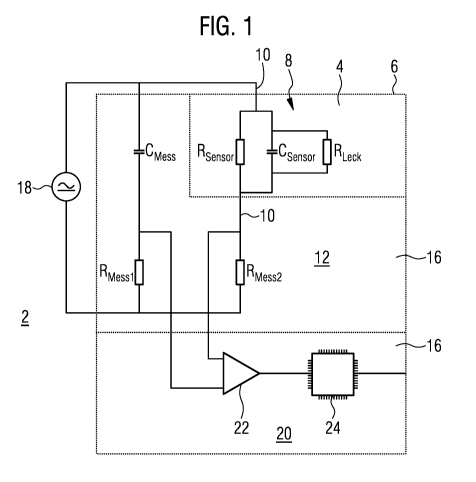
The leakage monitoring system 2 shown in Fig. 1 in a very abstract form serves
to
detect even the smallest changes which, over time, could lead to fluid or
medium guided
in a pipe 4 leaking through the pipe wall or exterior wall 6 to the outside.
The exterior
wall 6 thus forms the (as impermeable as possible) geometric limit of a flow
channel or
receiving volume for the enclosed medium or fluid.
CA 02933675 2016-06-13
9
A further example is the monitoring of planar plastics components, as used in
container
construction.
For this purpose, a sensor 8 in the form of an electrically conductive
material, here for
example in the form of a wire mesh or woven fabric, is integrated in the
electrically non-
conductive shell material of the exterior wall 6, which consists of a plastics
material.
Specifically, the embodiment uses a GRP pipe, in the wall of which at least
one metal
fibre or carbon fibre or CFRP woven fabric has been incorporated as an
electrically
conductive sensor. GRP stands for glass fibre reinforced plastics material and
CFRP
stands for carbon fibre reinforced plastics material. The extent of the
conductive woven
fabric preferably covers the whole of the wall surface to be monitored.
The electrically conductive woven fabric is connected at two points, which are
as far
away from one another as possible, for instance at either end of the pipe, to
one
electrical supply line 10 in each case, which is guided out of the exterior
wall 6 of the
pipe 4. The bipolar sensor 8 implemented thereby can be generally
characterised in the
equivalent circuit diagram shown as a parallel circuit of an ohmic resistor
RSensor and a
capacitor C5e501. The equivalent circuit diagram is only to be understood by
way of
example; more complicated cases may occur in practice which have alternatively
or
additionally available inductors in a parallel circuit and/or series circuit.
In the case of an impending leakage of fluid or medium guided in the pipe 4
through the
exterior wall 6 to the outside, caused for example by mechanical wear or
damage, at
least one of the electrical parameters of resistance, capacitance and/or
inductance of
the sensor 8 changes. Reasons for this could be, for example, a local change
in the
dielectricity and/or mechanical deformation of the conductive woven fabric at
breaking
points. This is shown in the equivalent circuit diagram (again only by way of
example) by
the ohmic additional resistor Reck, here in a parallel circuit with the
resistor Rsen501. In
general, the capacitance and the inductance of the sensor 8 can change as a
result of
the change in the pipe wall and/or the leakage flow. Very generally, it can be
said that
the complex AC resistance (impedance) of the sensor 8 changes when there is a
leakage-encouraging structural change.
In order to detect impedance changes of this kind, which can turn out
comparatively
small for minor changes, the sensor 8 integrated in the pipe 4 is coupled via
its supply
CA 02933675 2016-06-13
lines 10 into an AC voltage measuring bridge (measuring bridge 12 for short),
which is
constructed according to the basic principle of a Wheatstone measuring bridge
and is
implemented specifically for example as a Wien bridge or Maxwell-Wien bridge.
The
electronic components required for the completion of the bridge circuit and
for the
evaluation, which are shown here purely schematically and by way of example by
means of a measuring resistor RMessl, a measuring resistor RMess2 and a
measuring
capacitor CMess, are transferred into a measurement circuit 16 arranged
outside the pipe
4. In general, the measurement circuit 16 can comprise three complex measuring
resistors instead of the idealised electrical components RMessl, RMess2 and
CMess, which
resistors form, together with the complex sensor resistor of the sensor 8, the
measuring
bridge 12, on the bridge branch of which a voltage signal VMess (diagonal
voltage or
bridge transverse voltage) is sensed.
In the embodiment, the voltage signal Vmess sensed in the analogue part of the
measurement circuit 16 is supplied to a digital evaluation device 20 via
corresponding
connections and wires, which device comprises, for example, an operational
amplifier
22 or other signal amplifier and a microcontroller 24. A display device (not
shown) is
expediently provided for the purpose of visualising the measurement results
which are
processed in the evaluation device 20 and optionally assessed with respect to
a
possible leakage.
In contrast to the DC voltage-powered Wheatstone bridge, the measuring bridge
12 is
powered by a voltage source 18 having an operating voltage UG, which contains
both
AC voltage components, preferably having a single fixed base frequency w, and
DC
voltage components, specifically in the form of a superimposition or
superposition, thus
for example U(t) = U0 + U1 cos(wt). The bridge transverse voltage Vmess sensed
in the
bridge branch therefore usually changes drastically, even if the impedance of
the sensor
8 only changes slightly as a result of a leakage or a structural change
leading to a
leakage.
This is illustrated in Fig. 2, which shows the voltage signal VMess applied in
the bridge
branch as a function of time t. We see that a change to the monitored pipe
section that
encourages or is associated with a leakage and is applied at a time to has a
drastic
impact on the signal shape, in particular increases the signal-to-noise ratio,
and this can
be used to trigger an alarm manually or in an automated manner. In addition,
further
CA 02933675 2016-06-13
11
functional modules (not shown here) can be integrated in the measurement
circuit 16
according to Fig. 1 or can be coupled thereto.
Fig. 3 illustrates a specific case of the monitoring apparatus in a GRP
pipeline,
specifically in the region of the coupling 30 between two pipe segments 32,
34. A first
pipe segment 32, here the left-hand segment, comprises at its end a portion
having a
tapering external diameter and is inserted with a perfect fit into a second
pipe segment
34, here the right-hand segment, which comprises at its end a portion having a
correspondingly widening internal diameter. Two peripheral 0-ring seals 36
seal the
annular/hollow cylindrical gap 38 between the two pipe segments 32, 34. In
addition, a
peripheral clip 40 functions as a mechanical catch and lock for the coupling
30. For
example, a bayonet lock or the like can be provided.
For (preventative) detection of imminent or occurring leakage of flow medium
from the
inside of the pipe through the gap 38 into the surroundings, as can
particularly occur
when there is damage to the two 0-ring seals 36, a leakage sensor 42 is
integrated in
the coupling region. Here, the leakage sensor 42 substantially comprises two
(generally
at least one) electrically conductive rings 44 which are attached to the inner
pipe
segment 32 and protrude into the gap 38 and which form the electrodes of an
associated measurement circuit, which can consist of a bridge circuit powered
simultaneously by AC voltage and DC voltage, similarly to the embodiment
according to
Fig. 1. The explanations there with regard to the measuring principle and to
the
evaluation and alarm triggering also apply similarly here.
Fig. 4 enlarges some of the details from Fig. 3, specifically the detailed
shape and the
electrical contacting of the electrodes 46. We see that the metal-braid rings
44 which
protrude into the gap 38 between the two pipe segments 32, 34 and form the
electrodes
46 are contacted by metal sleeves 50 which are arranged radially in
corresponding
recesses in the pipe wall 48 of the inner pipe segment 32. At the opposite
end, the
metal sleeves 50 are each connected by an electrically/mechanically stable
connection,
here by means of spot welding using a contact clip 52 embedded in the pipe
wall 48, to
which clip an electrical supply line 54 is clamped using a connecting element
56.
One of the metal sleeves 50 is shown enlarged in cross section in Fig. 5. Said
sleeve
comprises a cylindrical anchor part 58 which is securely inserted into the
pipe wall 48,
CA 02933675 2016-06-13
12
and an attachment part 62 in the form of a spike which can be screwed into the
anchor
part 58 by means of a threaded extension 60. In the final assembled state, the
tip of the
spike protrudes from the pipe wall 48 and into the gap 38. At the end
protruding into the
pipe wall 48, the anchor part 58 is welded at its end face to the contact clip
52, which is
shown by the brazing solder weld seam 64.
The attachment part 62 can be removed after production for the purpose of
electrical
contacting. An electrical connection is then possible at the threaded
extension 60, which
connection is part of the measurement circuit shown in Fig. 1.
CA 02933675 2016-06-13
13
List of reference signs C Capacitor
R Resistor
2 Leakage monitoring system U, V Voltage
4 Pipe
6 Exterior wall t Time
8 Sensor
Supply line
12 Measuring bridge
16 Measurement circuit
18 Voltage source
Evaluation device
22 Operational amplifier
24 Microcontroller
Coupling
32 Pipe segment
34 Pipe segment
36 0-ring seal
38 Gap
Clip
42 Leakage sensor
44 Ring
46 Electrode
48 Pipe wall
Metal sleeve
52 Contact clip
54 Supply line
56 Connecting element
58 Anchor part
Threaded extension
62 Top part
64 Weld seam
Contact sleeve