Note: Descriptions are shown in the official language in which they were submitted.
1
APPARATUS FOR HANDLING MATERIAL, AND WASTE
CONTAINER/SEPARATING DEVICE
Background of the invention
The invention relates generally to material conveying systems, such as to
partial-
vacuum conveying systems, more particularly to the collection and conveying of
wastes, such as to the conveying of household wastes.
Systems wherein wastes are moved in piping by means of a pressure difference
or
suction are known in the art. In these, wastes are conveyed long distances in
the
piping by sucking. It is typical to these systems that a partial-vacuum
apparatus is
used to bring about a pressure difference, in which apparatus a partial vacuum
is
brought about in the conveying pipe with partial-vacuum generators, such as
with
vacuum pumps or with an ejector apparatus. A conveying pipe typically
comprises
at least one valve means, by opening and closing which the replacement air
coming into the conveying pipe is regulated. Input points, such as refuse
chutes,
are used in the systems at the material input end, into which input points
material,
such as waste material, is fed and from which the material to be conveyed is
conveyed into a conveying pipe by opening a discharge valve means. The
conveying of wastes occurs mainly by the aid of a pressure difference produced
by
an air flow. The air flow is generally brought about by sucking air through
the
piping. Waste material, such as e.g. waste material packed into bags, is
conveyed
from an input point into a conveying pipe and onwards into a separating
device,
where the wastes are separated from the transporting air. In connection with
the
separating device can be a transfer means, such as a transfer means arranged
on
a cylinder-piston combination, with which transfer means the wastes are
displaced
from the separating device into a waste container, e.g. into a freight
container.
These types of solutions comprising a separate separating device, e.g. a
cyclone
separator, and a waste container separate to it, are well suited to extensive
systems in which the space requirements of the waste station do not set
limitations. Also known in the art are solutions wherein waste material is
conducted in a conveying pipe directly into a waste container, which
simultaneously functions as a separating device. These are mainly intended for
rather small systems. This type of waste container/separating device is often
arranged to be a kind of freight container. In the art they are called
horizontal
separator containers. A problem in prior-art combinations of a waste container
and
6712012
Date Recue/Date Received 2021-07-26
2
separating device, more particularly in horizontal separator containers, is
that in
them a part of the material, or certain types of materials, remain in the
container
space loosely packed and thus take up space. On the other hand the waste
material or recyclable material is in many embodiments packed into bags or
sacks,
which can in many cases break when it is conducted along with the transporting
air into a waste container. This increases, inter alia, hygiene problems, as
wastes
are able to spread freely in the waste container.
The aim of the present invention is to achieve an entirely new type of
solution in
connection with a waste container/separating device of a pneumatic wastes
conveying system. One aim of the invention is to achieve a waste
container/separating device, by the aid of which the problems of prior art are
avoided. Another aim is to achieve a combination of a waste
container/separating
device and a press device, by means of which material can be efficiently
condensed into the container space of the waste container/separating device.
Brief description of the invention
The solution according to the invention has a number of important advantages.
One advantage, among others, achieved with the solution according to the
invention is that a separate separating device is not needed, but instead the
waste
container functions as an effective separator device and at the same time
material
can be efficiently compacted in it. In the solution of the invention,
therefore,
material can be conducted directly into, and material can be compacted in, the
waste container, which is preferably formed to be a container of the mobile
freight
container type. By arranging a wall in the container space of the waste
container/separating device, in which wall is an aperture, the feeding of
material
into the container space through the aperture of the wall is enabled at least
in the
starting phase of filling the container. When the container space has filled
to the
wall up to the height of the aperture, it prevents the return or displacement
of
material being fed in and/or being compacted in the container space. When the
material being fed in no longer passes through the aperture, the material
being fed
in is guided into the operating area of the press. When the waste material
conducted through the aperture collides in the container space with the
material
already fed in there, its speed effectively stops, but more softly than if it
had
collided with a hard wall. In this case the material being fed into the
container at a
fairly high speed (e.g. in the region of 80 km/h) stays intact better. In
addition, the
6712012
Date Recue/Date Received 2021-07-26
3
solution affects a possible noise problem by producing a noise that is lower
in
volume and softer. When the wall and the infeed via the aperture into the
container
space "behind" the wall are combined, an effective solution is achieved for
compressing material and compacting it, i.e. condensing it, in the container
space.
When the container space behind the wall fills, the compacting of the material
with
the press is started. In this case in the filling stage the compacting
occurring by
means of the press can be started only according to need, and the press does
not
need to be used in the starting phase of the filling of the container. This,
inter alia,
saves energy. The wall also prevents the return or displacement of compressed
material in the container space backwards past the press. The wall part is
thus
adapted to prevent the passage of compressed material in the opposite
direction
to the compression direction, in which case material can be condensed into the
container space efficiently with the press. By using a movable part that has a
support surface, the wall part can be supported when the press is used. In
this
case material can be efficiently compacted into the container part better than
before. The movable part can be a part of the press device, e.g. a moving
frame of
the press. The press device can have different embodiments, in which case the
effective compression distance and other properties of it can be adapted
according
to the application site. The movable part can have an aperture on the side
from
which material is conducted via the input aperture into the container, in
which case
it can be used for the effective conducting of material into the operating
range of
the compression means. When the compression pressure of the press rises to a
regulated value, the press part can be pulled out of the container space of
the
waste container/separating device, in which case material can be fed in and
can fill
the volume of the container space reserved by the press. In this case abundant
material can be made to fit and be compacted in the container space. The
solution
according to the invention enables well e.g. waste material packed into bags
or
sacks or the storing of recyclable material in bags regardless of their high
speed of
arrival into the container space. This enables the effective sorting of
material,
packed into bags or sacks, fed into the container space e.g. in a sorting
center to
which the container is taken for emptying. The sorting can be performed e.g.
by
means of an RFID identifier arranged in the bags or in the closing means of
the
bags or on the basis of some other radio-frequency identifier or optical
identifier.
The waste container/separating device can be emptied easily, because the wall
in
the container space is arranged to be turnable away from the front, e.g. by
hinging,
in which case it does not hinder the emptying.
6712012
Date Recue/Date Received 2021-07-26
4
Brief description of the figures
In the following, the invention will be described in more detail by the aid of
an
embodiment with reference to the attached drawings, wherein
Fig. 1 presents a simplified and partially cross-sectioned view of an
embodiment of
the invention in connection with a pneumatic conveying system for wastes,
Fig. 2 presents an embodiment of the waste container/separating device
according
to the invention, cross-sectioned along the line II-II of Fig. 4,
Fig. 3 presents an embodiment of the waste container/separating device
according
to the invention, cross-sectioned along the line III-Ill of Fig. 2,
Fig. 4 presents an embodiment of the waste container/separating device
according
to the invention, cross-sectioned along the line IV-IV of Fig. 2,
Fig. 5 presents an embodiment of the waste container/separating device
according
to the invention, in the emptying position
Fig. 6 presents an embodiment of the apparatus according to the invention,
cross-
sectioned along the line VI-VI of Fig. 7, in a first position,
Fig. 7 presents an embodiment of the apparatus according to the invention,
cross-
sectioned along the line VII-VII of Fig. 6,
Fig. 8 presents a cross-section of an embodiment of the apparatus according to
the invention, in a second position, cross-sectioned along the line VIII-VIII
of Fig.
9,
Fig. 9 presents an embodiment of the apparatus according to the invention,
cross-
sectioned along the line IX-IX of Fig. 8,
Fig. 10 presents a cross-section of an embodiment of the apparatus according
to
the invention, in a first operating phase,
6712012
Date Recue/Date Received 2021-07-26
5
Fig. 11 presents an embodiment of the apparatus according to the invention in
a
second operating phase, sectioned along the line XI-XI of Fig. 12,
Fig. 12 presents an embodiment of the apparatus according to the invention in
a
second operating phase, sectioned along the line XII-XII of Fig. 11,
Fig. 13 presents an embodiment of an apparatus according to the invention,
Fig. 14 presents an embodiment of an apparatus according to the invention in a
fourth operating phase, and
Fig. 15 presents an embodiment of an apparatus according to the invention,
cross-
sectioned along the line XV-XV of Fig. 14.
Detailed description of the invention
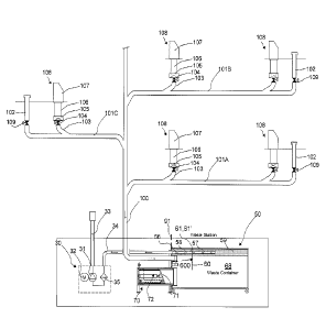
Fig. 1 presents a diagram of a part of a pneumatic material conveying system,
which part comprises a material conveying pipe 100, along the side of which at
least one, typically many, input points 108 are arranged. An input point 108
is a
feed-in station of material, more particularly of waste material, intended for
transporting, from which station the material, more particularly waste
material,
such as household waste, or recyclable material intended for transporting is
fed
into the conveying system. An input point 108 can also be a refuse chute, into
which material is fed from input apertures on different floors of a building.
The
system can comprise a number of input points 108, from which the material
intended for transporting is fed into conveying piping 100, 101A, 101B, 101C.
By
opening and closing a shut-off means, such as a valve means 104, that is
possibly
in connection with the feed-in station, material can be conveyed from an input
point 108 into the conveying pipe 100. The input point 108 is connected on the
valve side to the conveying pipe 100 or to an inlet pipe 103 in connection
with it.
Typically conveying piping comprises a main conveying pipe 100, to which it
has
been possible to connect a number of branch conveying pipes 101A, 101B, and in
turn to which branch conveying pipes it has been possible to connect a number
of
feed-in stations 108. In the embodiment of Fig. 1 the input point 108 is an
input
point 107 of waste material, said input point 107 being disposed on the
surface of
the ground. The input point 108 is connected via a feed-in channel 106 to a
6712012
Date Recue/Date Received 2021-07-26
6
material shaper 105, which shapes and condenses the material to fit into
conveying piping 103, 101A, 101B, 101C, 100 smaller in diameter than the feed-
in
channel. The solution according to the invention is also suited to those types
of
material conveying systems in which material shapers are not used, but instead
the material is conveyed from input points directly into the conveying piping.
The
conveying piping can be arranged to travel underground. In the embodiment of
the
figure the conveying piping comprises replacement air ducts 102, in which a
replacement air valve 109 is arranged.
An essential device in the invention is the waste container/separating device
50,
which is according to the invention a combination of a material collection
container, which is formed from a container, and of means arranged in it
separating the transporting air and the material being conveyed from each
other.
According to one embodiment the waste container/separating device 50 is a
movable container/separating device, for example a so-called horizontal
separator
container. The conveying pipe 100 can be connected to the waste
container/separating device 50, in which the material being transported is
separated from the transporting air. An input aperture 55, into which a
conveying
pipe 100 can be fitted, is formed in the wall of the waste
container/separating
device 50, which wall is an end wall 54 in the figure and which in the
embodiment
of the figure is also an openable and closable door. In Fig. 2 the end of the
conveying pipe 100 is fitted into the input aperture 55, inside the wall 55'
of it. A
joint means can also be formed in the conveying pipe 100 and a counterpart in
the
wall of the container, in the input aperture 55, such as a collar formed from
the wall
.. 55'. The joint means and the counterpart can in this case together form a
joint
means, e.g. a snap-on coupling. A connection 56 is formed in the waste
container/separating device 50, to which connection a pipe or hose 34 coming
from a partial-vacuum generator 31, from the suction side of it, of a partial-
vacuum
source can be connected with a counterpart.
In the embodiment of Fig. 1 the partial-vacuum source 30 of the pneumatic
waste
conveying system comprises a partial-vacuum generator 31, which is driven with
a
drive device 32. The partial-vacuum generator 31 can be e.g. a vacuum pump,
fan
or some other means bringing about negative pressure. The suction side of the
partial-vacuum generator 31 is connected to a waste container/separating
device
50 via a medium pathway 34. In this case the suction/pressure difference
needed
in the conveying of material can be brought about in the waste
6712012
Date Recue/Date Received 2021-07-26
7
container/separating device 50, in its container part 68, and via the input
aperture
55 in the conveying piping 100, 101A, 101B, 101C. Between the partial-vacuum
generator 31 and the waste container/separating device 50 is a filtering
device 35.
On the blowing side of the partial-vacuum generator 31 is an exhaust duct 33.
The
partial-vacuum source 30, the partial-vacuum generator 31 of it, can be
connected
from the suction side via the medium pathway 34 to the waste
container/separating device 50 with a counterpart arranged in the connection
56.
The waste container/separating device 50 according to an embodiment of the
invention is presented in more detail in Figs. 2-4. In the solution according
to Figs.
2 ¨ 4 the waste container/separating device 50 comprises a base 52, an end
wall
51, a top wall 53, side walls 66, 67 and a second end wall, which in the
embodiment of the figure is an openable and closable door 54. The walls 51,
52,
53, 54, 66, 67 bound the container space 68. A wall 60 is arranged in the
container
space 68, which wall extends from the top part of the container a distance
towards
the bottom part of the container when the wall 60 is in a vertical position.
In the
embodiment of Figs. 2-4 the wall 60 is arranged to be hinged at its top part
61
around the axis 61' to the top wall 53 of the container. The wall 60 is
therefore
turnable in relation to the transverse axis 61'. The wall 60 is arranged to a
part of
the height of the container space 68, in which case a free space is between
the
bottom part 62 of the wall 60 and the base 52 of the container. The wall 60 is
arranged at the point of the input aperture 55 in the height direction of the
container, and at a distance from it in the longitudinal direction of the
container. An
aperture 600 is arranged in the wall 60, which aperture extends from the first
side
of the wall 60 to the other side of the wall, i.e. through the wall. The
aperture 600 is
arranged in the wall 60 at a point to which the material w being fed into the
waste
container/separating device via the input aperture 55 is carried. In Figs. 8
and 10
one path of travel P of material in the container space 68 is presented with a
dashed line. In this case the material w being fed in is thrown when fed in
from the
input aperture 55 through the aperture 600 of the wall 60 into the part of the
container space 68 situated after the wall 60 in the travel direction. It is
possible to
bring about the throwing of the material through the aperture 600 up until, as
the
container space 68 fills, the material w that has been fed into the container
space
68 and accumulated in it extends to the point of the aperture 600. In the
embodiments of Figs. 4, 7, 9 the aperture 600 is round, but it can also be of
another shape. For example, in Fig. 13 the width of the aperture is greater
than its
height. Of course, the height can be greater than the width, depending on the
6712012
Date Recue/Date Received 2021-07-26
8
application site. It can also be conceived that the wall 60 is formed from a
number
of wall parts side-by-side or one above another, between which at least one
aperture 600 is formed or arranged. In Fig. 4, a gap remains between the side
edges of the wall 60 and the side walls 66, 67 of the waste
container/separating
device. According to one preferred embodiment the wall is a flap that is
hinged at
its top edge. The wall 60 in Figs. 2 ¨ 4 is planar, but it can also be another
shape,
e.g. concave, convex or corrugated. The wall can be e.g. of metal such as
steel, or
of a plastic material, rubber material or combinations of these. Other
suitable
materials can be considered, depending on the application site.
In the embodiment of the figure, the waste container/separating device 50 has
at
least one suction pipe 57, which extends from the connection 56 into the
inside
space of the waste container/separating device. In the embodiment of Figs. 2 -
4 a
suction pipe 57 is arranged in the top part of the container space 68 of the
waste
container/separating device in the orthogonal cross-section (Fig. 4) of the
container with respect to the longitudinal direction in the corner area, or in
the
proximity of same, between the top wall 53 and the side wall 66 and/or 67. In
the
embodiment of Figs. 2-4 the waste container comprises two suction pipes 57. Of
these, the first is arranged in the orthogonal cross-section (Fig. 4) of the
container,
with respect to the longitudinal direction of the container, in the corner
area, or in
the proximity of same, between the top wall 53 and the side wall 66 and the
second suction pipe is arranged in the corner area, or in the proximity of
same,
between the top wall and the second side wall 67. A connection to the suction
side
of the partial-vacuum generator, i.e. suction, can be arranged via either one
of the
suction pipes or via both suction pipes. By varying the suction, e.g. the
strength of
the suction, between different suction pipes 57 the placement of material
evenly in
the container space 68 can be made more efficient. In this case by altering
the
point at which the suction acts or the strength of its action in the container
space of
the material container, the input direction and path of travel in the
container space
of material being conducted from the input aperture 55 into the container
space 68
can be influenced.
At least one suction aperture 58 is arranged in the suction pipe 57 for the
length of
it. In the embodiment of Figs. 2-4 there are a number of suction apertures 58
for
the length of the suction pipe 57 and possibly also arranged on the rim of the
wall
of the suction pipe 57. A wall part 59, such as dense netting, that allows air
to pass
through is also arranged in the container space 68, which wall part allows air
6712012
Date Recue/Date Received 2021-07-26
9
through but prevents the passage of at least large-sized waste material
particles
into the suction pipe 57 from the suction apertures 58. The wall part 59 that
allows
air to pass through and the top wall 66 of the container and one of the two
side
walls 66 or 67 form the longitudinal chamber space of the container, into
which
chamber space the suction pipe 57 is arranged. When the suction side of the
partial-vacuum generator 31 is connected to act via the medium channel 34 and
the connection 56 in the suction pipe 57, the suction acts via the suction
apertures
58, and through the wall 59 that allows air to pass, into the container space
68 of
the waste container/separating device and onwards via the input aperture 55
into
the conveying piping 100, 101A, 101B, 101C.
An aperture 69 is arranged in the waste container/separating device 50 for
bringing at least the press part 71 of the press device 70 into the container
space
68. In Figs. 2-4, the aperture 69 has a collar 69', which extends into the
container
space. In the embodiment of Figs. 2-4 the aperture 69 for the press device is
arranged in the same wall 54 as that in which the input aperture 55 is
arranged,
and below the input aperture 55 in the height direction.
According to one embodiment a hatch 91 is arranged to cover the aperture 69,
which hatch is displaced from in front of the aperture 69 when the press
device 70
is connected into connection with the waste container/separating device 50. In
the
embodiment of Figs. 2-4, the door of the wall 54 is hinged to turn around a
vertical
axis 98, which is illustrated in Fig. 3. The door 54 can be turned in the open
position against the outer side of the side wall 67 of the waste
container/separating
device, as is illustrated in Fig. 3 with dashed lines. This is a preferred
position for
the door when the container is emptied.
Fig. 5 presents a situation in which the waste container/separating device 50
is in
the typical emptying position. It can be seen from the figure that the wall 60
in the
container space 68 turns, preferably around the axis 61' owing to the hinging
of its
top edge 61, when emptying the container of material from the front, in which
case
emptying can be performed quickly and efficiently. Friction-reducing means,
e.g.
roller means according to the figure, which facilitate the moving of the waste
container/separating device, can be arranged on the bottom part of the waste
container/separating device 50.
6712012
Date Recue/Date Received 2021-07-26
10
Figs 6-9 present an embodiment of the device according to the invention,
wherein
a press device/compactor device 70, comprising a compression means 71 and its
drive device 72, is arranged in connection with the waste container/separating
device 50. The compression means 71 in the press device/compactor device 70 in
the embodiment of the figure is arranged to be movable between at least two
positions. The compression means 71 is arranged to displace and condense the
waste material in the container part 68. The compression means displaces and
simultaneously also compresses the material w to be denser, i.e. it compacts
the
waste into the container space 68. In the embodiment of Figs. 6-9 the press
device/compactor device 70 comprises a frame 77, in which the compression
means 71 and its moving apparatus are arranged in a first position, i.e. the
standby position. The frame 77 comprises a joint part 80, which is adapted in
such
a way that the counterpart, typically a collar 69', of the aperture 69 of the
waste
container/separating device 50 forms a joint with the joint part 80. In the
embodiment of Figs. 6-9 the collar 69' is arranged around the joint part 80 of
the
frame 77 of the press device/compactor device 70. The frame 77 is arranged in
the embodiment of the figure on a machine bed resting on support legs 78. A
pathway for medium is arranged in the frame 77 from the space in which the
compression means is moved to the outside and to a valve means 79 there, which
is a so-called blow valve.
Figs. 6-14 present one embodiment of the invention. Likewise, Figs. 6-9
present
the bringing of a waste container/separating device 50 and connection of it
into
connection with a press device/compactor device 70 as well as with a conveying
pipe 100 and with a channel 34 of a partial-vacuum generator. In Fig. 6 the
waste
container/separating device 50 is moved towards the press/compactor. The joint
part 80 of the press/compactor device 70 and the end of the conveying pipe 100
as well as the end of the suction channel 34 are arranged, for example, in a
supported manner in such a way that the necessary joints form, or are formed,
when the waste container/separating device 50, the counterparts on it, the
press
aperture 69, input aperture 55 and connection 56 are brought against the joint
part
80 and the end of the conveying pipe 100 and the end of the suction channel
34.
According to one embodiment the hatch 91 is arranged to cover the aperture 69,
which hatch is displaced from the position of Figs. 6 and 7 upwards into the
position of Figs. 8 and 9, away from the front of the aperture 69, when the
press
device 70 is connected into connection with the waste container/separating
device
50.
6712012
Date Recue/Date Received 2021-07-26
11
In the embodiment of Figs. 6-9 a movable part 89 functioning as a moving frame
of
the press is arranged into connection with the press device/compactor device
70,
which movable part when extended settles in the proximity of the bottom part
62 of
the wall 60 arranged in the container space 68 of the waste
container/separating
device 50 and if necessary supports the wall 60 preventing its essential
movement, such as a rotary movement around the axis 61', towards the wall 54
on
the side of the input aperture 55. The movable part 89 has a support surface
90,
against which the bottom part 62 of the wall 60 can rest. The movable part 89
has
an aperture 92, which opens in the container space on the side of the input
aperture 55 when the movable part 89 is taken into the second position (Fig.
10).
From the aperture 92 material can pass to in front of the compression means 71
when the compression means is in the position according to Figs. 10 and 13.
The
actual compressing movement of the compression means 71 and compacting of
material w is performed according to Fig. 13, from the position of Fig. 13
into the
position of Fig. 11.
In the embodiment of Figs. 6-14 the drive apparatus 72 of the press
device/compactor device 70 comprises a two-phase arrangement, in which a first
drive device 82, 83 is arranged to move the movable part 89, which is now the
moving frame of the press, as well as a second drive device 87, 88 and the
compression means 71 connected to it into a second position (Fig. 10 and Fig.
13).
From the second position the compression means 71 is moved with the second
drive device 87, 88 into a third position, which is presented in Fig. 11.
The first drive device 82, 83 is arranged at its first end 73, in the figure
on the side
of the cylinder 82, on the structures of the frame 77. At its second end 84,
in the
figure on the side of the rod 83 of the piston, the first drive device 82, 83
is
arranged on a coupling part 85, on which the movable part 89 is arranged or
which
is a part of the movable part 89. The first end 86, in the figure the cylinder
part 87,
of the second drive device 87, 88 is in turn connected to the coupling part
85. The
second end 76, in the figure on the side of the rod 88 of the piston, of the
second
drive device 87, 88 is connected to the compression means 71.
6712012
Date Recue/Date Received 2021-07-26
12
In the embodiment of Figs. 6-14 the material can be efficiently guided via the
aperture 92 of the movable part 89 to in front of the compression means for
displacing and compressing into the container space, when the material is no
longer able to go into the actual container space via the aperture 600 of the
wall
60. In addition, a long compression stroke and an effective compacting of the
material w into the container space 68 are achieved. In addition, the support
surface 90 of the movable part 89 effectively prevents the undesired movement
of
the wall 60 towards the input aperture 55, and thus also for its part enhances
the
compaction of wastes in the container space 68. The wall 81 of the compression
means 71 prevents passage of the material via the aperture 92 when the
compression means is in the position of Fig. 11, i.e. in the compression
position. In
the embodiment of the figure the movable part 89 is tubular and can also
function
as a part of the bottom wall for the separating space 68' when the movable
part 89
is in the second position, i.e. extended into the container 68.
Material w, such as household waste, is fed in from an input point 108 into
the
piping 101A, 101B, 101C, 100, where it is conveyed by the aid of suction/a
pressure difference and/or transporting air flowing in the piping into the
waste
container/separating device 50 from the input aperture 55. When the container
space of the waste container/separating device is empty or there is only a
small
amount of material in the container space 68 of the waste container/separating
device, the movement path P of the material typically follows the trajectory
presented with a dashed line in Figs. 8 and 10. In this case the material is
thrown
a distance from the input aperture 55 through the aperture 600 of the
transverse
wall 60 and collides with the material w that is already in the container
space 68 or
with the wall 51 of the container and drops into the container space 68.
The material is thus separated from the transporting air, e.g. by the aid of
collision
and gravity, in such a way that heavier material W travels to the bottom part
of the
container. A suction pipe 57 is arranged in the top part of the waste
container/separating device 50, which pipe is connected to the suction side of
the
partial-vacuum generator 31. The transporting air leaves the container part 68
of
the waste container/separating device into the suction pipe 57. The wall 59
allowing air to pass through prevents the passage of at least the larger
material
particles into the suction pipe. The smaller particles are filtered in the
filtering
device 35 (Fig. 1).
6712012
Date Recue/Date Received 2021-07-26
13
The material is conducted into the container space 68 according to Figs. 10
and
11. When the rear part that is after the wall 60 of the container space 68
starts to
be full, so that the material is no longer able to go into the actual
container space
through the aperture 600 of the wall 60 but instead drops, e.g. guided by the
material w blocked by the wall 60 or aperture 600, via the aperture 92 to in
front of
the compression means 71 of the press, the compression means starts to be
moved between the second position presented by Fig. 13 and the third position
(compression position) presented by Fig. 11. In this case the material
displaces
farther in the container space 68, pushed by the compression means of the
press.
With the compression means the material is displaced farther in the container
space 68 from below the wall 60. The compression means 71 is moved
reciprocally with the drive apparatus 72 between the second position of Fig.
13
and the third position of Fig. 11. It is also possible that the compression
means 71
is moved only a part of the distance between the aforementioned extreme
positions. When sufficient material collects in the container space 68, the
compression means 71 compresses it, e.g. against the end wall 51, to be
denser.
The wall 60 arranged in the container space for its part prevents the
compressed
material w from returning in the container space 68 in an undesired manner to
the
input aperture 55 side with respect to the wall 60 in the container space 68.
This
part of the container space 68 is marked in the figure with the marking 68'.
It can
be called the separating part of the container. This space is bounded above by
the
top wall 53 of the container and the wall 59 that allows air through, the end
wall 54
(i.e. the door) and the wall 60 arranged in the space, and below by at least
one
wall of the press device/compactor device 70 when it is pushed into the
container
space at least partly. In the embodiment of Fig. lithe wall bounding the space
68'
of the press device is the top wall 81 of the compression means.
When the compression pressure rises up to a set limit the compacting is ended
and the press is pulled into the position of Fig. 14 out of the container
space, after
which the container space reserved from the container space by the press, as
well
as the space 68' between the input aperture 55 of the container and the wall
60
can, still be filled. By means of the embodiments of the invention the
container
space of a waste container/separating device can be efficiently filled with an
arrangement in which the press is only needed in the end phase of filling the
container.
6712012
Date Recue/Date Received 2021-07-26
14
The filling can be made even more efficient by arranging the aperture 600 of
the
wall to be large in the width direction, e.g. according to the embodiment of
Fig. 14,
in such a way that the path of travel of material can be varied by varying the
suction, e.g. the strength of the suction, between the different suction pipes
57. In
this case the placement of material evenly in the container space 68 in the
transverse direction of the container can be made more efficient. In this case
by
altering the point at which the suction of the partial-vacuum source acts or
the
strength of its action in the container space of the material container, the
input
direction and path of travel in the container space of material being
conducted
from the input aperture 55 into the container space 68 also via the aperture
600
can be influenced.
The invention thus relates to an apparatus for handling material in connection
with
a pneumatic material conveying system, which apparatus comprises a waste
container/separating device 50, into which material is adapted to be conducted
from a conveying pipe 100 of the pneumatic material conveying system via an
input aperture 55 and which is adapted to be connected to means for achieving
a
partial vacuum. The apparatus further comprises a press device/compactor
device
70, which is arranged to act on the material w conducted into the waste
container/separating device 50, via at least one aperture 69 formed in the
container, and that at least one wall 60 that is transverse with respect to
the input
direction of the material is arranged in the container space 68 of the waste
container/separating device 50, and that at least one aperture 600 is arranged
or
formed in the wall 60, which aperture is fitted in the wall 60 on the path of
travel P
of the material w to be fed in via the input aperture 55, which wall 60 is
adapted to
control or limit the movement of material in the container space 68.
According to one embodiment the compression means 71 of the press
device/compactor device is arranged to move in the container space with a
drive
apparatus 72 between a first position and a second position.
According to one embodiment the compression means 71 of the press
device/compactor device 70 is adapted to move in the container space from the
first position, in which the compression means 71 is not essentially in the
container
space 68, into a second position, in which the compression means extends to at
least the point of the wall 60 in the container space 68.
6712012
Date Recue/Date Received 2021-07-26
15
According to one embodiment the apparatus comprises a movable part 89, which
comprises a support surface 90, which is adapted in the support position to
support the wall 60.
According to one embodiment the wall 60 is arranged to be turnable or bendable
at its top part 61 around a transverse axis 61'.
According to one embodiment the wall 60 is adapted to receive the load exerted
by the material w at least when it is supported with the support surface 90.
According to one embodiment an aperture 69 for the press device/compactor
device 70 is formed in the wall 54 of the waste container/separating device 50
essentially in the proximity of the input aperture 55, most suitably below it.
According to one embodiment the press device/compactor device 70 comprises a
movable part 89, which comprises a support surface 90 for the wall 60, which
movable part is arranged to be moved with a drive apparatus 72.
According to one embodiment an aperture 92 is formed in the movable part 89,
via
which aperture the material is guided into the operating range of the
compression
means 71.
According to one embodiment the wall 60 is adapted to limit the passage of
material w from the container space 68 in the opposite direction with respect
to the
compression direction.
The invention also relates to a waste container/separating device for
pneumatic
pipe transporting systems for material, which device comprises at least one
input
aperture for connecting it to a material conveying pipe, means for connecting
a
partial-vacuum generator to the container and means for connecting a press
device/compactor device. At least one wall 60 that is transverse with respect
to the
input direction of the material is arranged in the container space 68 of the
waste
container/separating device, and that at least one aperture 600 is arranged or
formed in the wall 60 from the first side to the second side of the wall,
which
aperture 600 is fitted in the wall on the path of travel P of the material to
be fed in
via the input aperture 55, which wall is adapted to control or limit the
movement of
material in the container space 68.
6712012
Date Recue/Date Received 2021-07-26
16
According to one embodiment the wall 60 extends to a part of the height of the
container space 68.
According to one embodiment the wall 60 is arranged to be turnable or bendable
at its top part 61 around a transverse axis 61'.
According to one embodiment the wall 60 is arranged at its top part 61 on the
upper wall 53 of the waste container/separating device or in the proximity of
said
upper wall.
According to one embodiment the wall 60 is adapted to rest, preferably at its
bottom part 62, on the support surface 90 of the press or on another support
surface.
According to one embodiment the wall 60 is arranged to turn away from the
front
when the waste container/separating device 50 is emptied of material w.
According to one embodiment the wall 60 is adapted to receive the load exerted
by the material w at least when it is supported with the support surface 90.
According to one embodiment the waste container/separating device 50 comprises
a suction pipe 57 arranged in the top part of the container space 68.
According to one embodiment the aperture 69 of the press arranged in the waste
container/separating device 50 and the input aperture 55 are in the proximity
of
each other, preferably in the same wall 54.
According to one embodiment the wall 60 is adapted to limit the passage of
material w from the container space 68 in the opposite direction with respect
to the
compression direction.
According to one embodiment the wall 60 is formed from a number of wall parts.
According to one embodiment the aperture 600 is adapted to allow different
paths
of travel P of the material w. In this case the input direction of the
material into the
6712012
Date Recue/Date Received 2021-07-26
17
container space can be controlled e.g. by varying the suction or the strength
of the
suction between the different suction pipes.
According to one embodiment the waste container/separating device is container
of the freight container type.
Typically the material is waste material, such as waste material arranged in
bags.
The refuse chute can be fitted to be a part of a pneumatic waste conveying
system
or it can be a separate part, in which waste material is conducted into the
waste
room, waste container or corresponding.
It is obvious to the person skilled in the art that the invention is not
limited to the
embodiments presented above, but that it can be varied within the scope of the
claims presented below. The characteristic features possibly presented in the
description in conjunction with other characteristic features can also, if
necessary,
be used separately to each other.
6712012
Date Recue/Date Received 2021-07-26