Note: Descriptions are shown in the official language in which they were submitted.
- 1 -
Process for producing ammonia synthesis gas
DESCRIPTION
Field of the invention
The invention relates to reforming of hydrocarbons for the preparation of a
synthesis gas, also named syngas, for the production of ammonia.
Prior art
The synthesis of ammonia (NH3) requires a synthesis gas comprising
hydrogen (H2) and nitrogen (N2) in a suitable ratio of about 3:1. The term
ammonia syngas will be used with reference to a synthesis gas with the
above composition.
It is known to produce said syngas from the reforming of a hydrocarbon (HC)
feedstock containing methane. Reforming takes place in a primary reformer
and then in a secondary reformer. Usually, the feedstock and a suitable
amount of steam are admitted into a primary reformer, where methane is
converted in a mixture of carbon monoxide, carbon dioxide and hydrogen by
passage over a suitable catalyst; the secondary reformer receives the gas
product delivered by the primary reformer, and an air flow. The reformed gas
leaving the secondary reformer is then purified in a shift conversion section,
a
CO2 removal section and a methanation section.
US 4 296 085 discloses a process for producing ammonia from a desulfurized
hydrocarbon containing feedstock available at a pressure of at least 30 bars,
comprising: dividing said feedstock into two fractions; subjecting only the
first
Date Recue/Date Received 2021-03-02
- 2 -
fraction from to a primary steam reforming reaction; combining the gaseous
effluent from said primary steam reforming with the second fraction of the
feedstock; reacting the mixture in a secondary reforming reactor. Purification
takes place in a high-temperature shift converter with iron-based catalyst and
then in a low-temperature shift converter.
Further background art of production of ammonia synthesis gas can be found
in EP 2 065 337.
A relevant parameter of the reforming process in the molar steam to carbon
ratio, that is the ratio between the moles of carbon introduced with the
hydrocarbon feedstock and the moles of steam.
The most common prior art is to operate the primary reformer with a high
steam to carbon ratio, that is greater than 2.6 and usually in the range 2.8 ¨
3.5, to avoid damage of the iron-based catalyst of the HTS converter.
EP 2 404 869 discloses: a process for producing ammonia synthesis gas from
a hydrocarbon-containing feedstock, the process comprising the steps of
primary reforming said feedstock with steam, secondary reforming with an
oxidant stream, and further treatment of the synthesis gas involving at least
shift, removal of carbon dioxide and methanation, wherein the synthesis gas
produced by said secondary reforming is subject to a medium-temperature
shift at a temperature between 200 and 350 C, and said primary reforming is
operated with a steam-to-carbon ratio lower than 2.
By lowering the steam to carbon ratio, the amount of gas processed in the
primary reformer can be increased. However, the need to compensate by
introduction of enriched air or oxygen in the secondary reformer may
negatively balance the above advantage, due to the higher investment cost of
the relevant air separation unit. More generally, there is a continuous
incentive to reduce the size and cost of expensive equipment like the
Date Recue/Date Received 2021-03-02
- 3 -
secondary reformer and the air separation unit.
Summary of the invention
The purpose of the invention is to overcome the above drawbacks.
Said purpose is reached with a process comprising the steps of primary
reforming said feedstock with steam, secondary reforming with an oxidant
stream, and further treatment of the synthesis gas involving at least shift
and
removal of carbon dioxide, and is characterized in that the synthesis gas
produced by said secondary reforming, optionally added with steam, is
subject to a medium-temperature shift over a copper-based catalyst, and the
global steam to carbon ratio of the process is not greater than 2.
The global steam to carbon ratio is determined by the total amount of the
moles of steam over the moles of carbon introduced with the feedstock.
According to a preferred embodiment of the invention, steam is added in
multiple stages of the process. A first amount of steam is added before the
primary reforming (possibly including a pre-reforming step), and a second
amount of steam is added before the medium-temperature shift conversion.
The medium-temperature shift conversion is preferably isothermal, which
means that heat is removed by a suitable heat exchanger immersed in the
catalyst. The catalyst is preferably a copper-zinc catalyst. The temperature
of
the shift conversion is preferably in the range 200 to 300 C and more
preferably around 250 C.
Oxydant stream for the secondary reforming may include air, oxygen-
enriched air or substantially pure oxygen. The substantially pure oxygen is
understood as oxygen as obtainable from an air separation unity, and has
preferably a purity equal to or greater than 95%.
In some embodiments, the primary reforming section is operated with a low
Date Recue/Date Received 2021-03-02
- 4 -
steam to carbon ration of 0.5 to 1.5. A low ratio, that is less than 1 and
possibly around 0.5, can be adopted especially in embodiments with a pre-
reformer. Then, the subsequent introduction of steam before the shift
conversion helps to convert the carbon monoxide and produce hydrogen as
desired.
In some embodiments, a portion of the hydrocarbon feedstock is made to by-
pass the primary reforming stage or (when provided) the pre-reforming stage.
Said bypass provides an additional degree of freedom in determining the local
steam to carbon ratio, for example a primary reforming stage by-passed by
some of the feedstock is brought to operate under a high ratio such as 2.5 to
3, while the global ratio is kept at a value of 2 or lower.
In another aspect, there is provided a process for producing ammonia
synthesis gas from a hydrocarbon-containing feedstock, the process
comprising the steps of: primary reforming with steam, secondary reforming
with an oxidant stream, and purification of the effluent of said secondary
reforming, said purification comprising a step of shift conversion of carbon
monoxide, wherein: the synthesis gas produced by said secondary reforming
is subject to a medium-temperature shift over a copper-based catalyst, and a
fraction of the feedstock bypasses the primary reforming, the steam to carbon
ratio in the primary reforming being 2.5 to 3, and/or steam is added in
multiple
stages of the process, wherein the global steam to carbon ratio of the process
that is the total amount of the moles of steam over the moles of carbon
introduced with the feedstock is not greater than 2.
The invention provides embodiments with or without a pre-reforming.
According to some embodiments, a fraction of the feedstock bypasses the
primary reforming section, either with or without a pre-reforming.
In some embodiments including a pre-reforming, the feedstock is divided into
two fractions. A first fraction is directed to the pre-reforming and primary
Date Recue/Date Received 2021-03-02
- 5 -
reforming, and a second fraction by-passes both the pre-reforming and
primary reforming and is fed to the secondary reforming together with the
effluent of primary reforming. In some other embodiments, the effluent of the
pre-reforming stage is divided into two fractions, a first fraction is
directed to
the primary reforming step and a second fraction bypasses said pre-reforming
step and is rejoined with the effluent thereof. A further amount of steam can
be optionally added to said first fraction.
The primary reforming stage is preferably operated with a steam to carbon
ratio of 1 to 1.5. In embodiments with a pre-reformer, said pre-reformer can
be operated at a lower steam to carbon ratio, as low as 0.5.
More in detail, some preferred embodiments are as follows.
In a first embodiment, a pre-reformer and a primary reformer are operated at
low S/C ratio of 1 to 1.5. Steam is added upstream the MTS to reach an
overall S/C of about 2 and improve the conversion of CO on the MTS catalyst.
In a second embodiment, some of the feedstock by-passes around the pre-
reformer and reformer. The feedstock from the by-pass is added at the inlet of
a secondary reformer or autothermal reformer with little or no steam, to
reduce the S/C ratio in the reforming area. Additional steam is introduced
upstream MTS but to a low overall S/C of about 2, to improve the conversion
of CO. The amount of additional steam depends on the amount of natural gas
bypassed around the reformer.
In a third embodiment, some of the feedstock, preferably at least 40-50%, by-
passes around a primary steam reformer, operated at S/C ratio of about 2.7-
3, which can be done without a pre-reformer. Steam is added upstream the
MTS but to a low overall S/C ratio of about 2.
In a fourth embodiment, all the incoming feedstock is pre-reformed at low S/C
ratio of 0.5 to 1.5, then some of pre-reformed gas by-passes the primary
Date Recue/Date Received 2021-03-02
- 6 -
reformer. Steam is added upstream the primary reformer and upstream the
MTS, but to a low overall SIC ratio of less than 2.
All the embodiments of the invention may include steps of carbon dioxide
removal and optionally of methanation.
Further process steps may be provided to purify the synthesis gas, in
particular to remove methane, unreacted hydrocarbons or inert gases. Said
further steps may include any of: cryogenic separation, pressure-swing
adsorption, or equivalent. In some embodiments, Inert gases and methane
can be removed from the purge gas taken from the synthesis loop, with a
known treatment such as for example a cryogenic process.
The advantages of the invention include a reduced size of cost-intensive
equipment including the reformers, the related piping which operates under
high temperature and pressure, and the air separation unit which provides
oxygen-enriched air or pure oxygen. The invention provides a better and
optimized exploitation of the various sections, thanks to the fact that the
steam to carbon ratio can be locally modified, e.g. featuring a pre-reformer
with a low ratio or a primary reformer with a higher ratio, while the global
ratio
is kept at a desired value by means of the addition of steam before the
medium-temperature shift stage.
The invention also includes a plant for the production of ammonia syngas and
a procedure for revamping an ammonia plant, according to the attached
claims.
An aspect of the invention is a procedure for revamping of an ammonia plant
comprising a front-end for production of a ammonia synthesis gas, and a
synthesis loop for reaction of said synthesis gas into ammonia, said front-end
comprising at least a primary steam reformer, a secondary reformer, a high-
temperature shift converter, said procedure comprising at least the steps of:
Date Recue/Date Received 2021-03-02
- 7 -
replacing said shift converter with a medium-temperature shift converter with
copper-based catalyst, or modifying the existing high-temperature shift
converter for operation at medium temperature and with a copper-based
catalyst; regulation of said steam line and other steam lines of the plant, if
any, in such a way that the revamped plant operates with a global steam to
carbon ratio which is not greater than 2.
Preferably, said procedure comprises also: the provision of at least one steam
line arranged to feed steam to the effluent of the secondary reformer, before
admission to the shift converter.
In some embodiments, the procedure comprises also the provision of a
bypass line around the primary reforming section, for a portion of feedstock.
In some other embodiments, the procedure comprises the provision of a
bypass line around a primary reformer, for a portion of the effluent of a pre-
reformer upstream the primary reformer.
The procedure of revamping according to the invention involves passing from
high-temperature shift (HTS) to medium-temperature shift (MTS). This can be
done by replacing an existing HTS reactor with a medium-temperature shift
reactor, or modifying the HTS reactor for operation at medium temperature
and with the appropriate catalyst.
The medium-temperature shift reactor is preferably isothermal. Then, the
revamping may involve for example one of the following alternatives:
i) keeping the existing vessel of the HTS reactor, replacing the high
temperature catalyst with a medium temperature catalyst, such as Cu-
Zn catalyst, and providing the vessel with an internal heat exchanger,
immersed in the catalyst, or
ii) installing a new MTS reactor with a suitable catalyst and internal heat
exchanger.
Date Recue/Date Received 2021-03-02
- 8 -
In both the above options, the heat exchanger is preferably a plate heat
exchanger.
In some embodiments, a pre-reforming section is also added upstream an
existing primary steam reformer.
According to preferred embodiments, the procedure may further comprise the
increasing of the amount of oxygen directed to a secondary reformer, by any
of the following measures: a) feeding excess air to said secondary reformer;
b) providing enrichment of air fed to the secondary reformer; c) feeding
substantially pure oxygen to the secondary reformer. To achieve the
aforesaid measures the revamping of the plant may provide that: a) the
existing air feed to the secondary reformer is modified to provide a larger
air
input, or b) a suitable equipment for air enrichment is installed, or c) a
suitable
source of substantially pure oxygen is installed, if not available. Said steps
may involve the modification or replacement of piping, valves, auxiliary
equipments, etc... according to known art.
According to still further embodiments, further equipments for syngas
purification may be installed, to provide any of the following: cryogenic
separation of excess methane and/or nitrogen in the ammonia syngas;
separation of excess nitrogen, if any, by an adsorption process such as PSA;
increasing the purge loop form the synthesis loop, to provide removal of inert
gases and residual methane.
An increase of capacity may be obtained without modifying the internals of
the primary reformer if, further to provision of MTS reactor instead of the
original HTS reactor, one or more of the following measures are taken:
- providing more oxygen to the primary reformer, by feeding excess air or
enriched air or pure oxygen to said primary reformer,
- improving the purification of the syngas by one or more of the techniques
Date Recue/Date Received 2021-03-02
- 9 -
listed above, i.e. cryogenic separation of excess methane and/or nitrogen in
the ammonia syngas; separation of excess nitrogen by means of adsorption;
increasing the purge of the synthesis loop.
Hence, the revamping procedure may include, when necessary, the
installation of the related equipments, such as air separation unit for air
enrichment or oxygen feed, cryogenic separator, PSA separation section. The
method may include also the revamping of the syngas main compressor,
synthesis reactor, and other equipments, to process the augmented flow rate
of syngas delivered by the front-end.
It should also be noted that the syngas flow delivered by the revamped front
end may contain less nitrogen than required to react the stoichiometric ratio
3:1 for synthesis of NH3. In this case, the missing nitrogen may be furnished
as a separate stream, which is added to the syngas preferably at suction side
or delivery side of the main syngas compressor. Said nitrogen stream could
be generated by an air separation unit.
Brief description of the figures
Fig. 1 is a scheme of a first embodiment of the invention.
Fig. 2 is a scheme of a second embodiment of the invention.
Fig. 3 is a scheme of a third embodiment of the invention.
Fig. 4 is a scheme of a fourth embodiment of the invention.
Fig. 5 is a scheme of a fifth embodiment.
Detailed description of a preferred embodiment
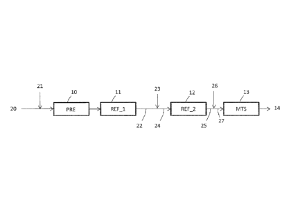
Fig. 1 discloses a scheme of a front-end for generation of ammonia synthesis
Date Recue/Date Received 2021-03-02
- 10 -
gas, comprising: a primary reforming section which includes a pre-reformer
and a primary reformer 11; a secondary reformer 12; a medium-
temperature shift (MIS) converter 13. The pre-reformer, primary reformer and
secondary reformer are also denoted by symbols PRE, REF_1 and REF_2.
5 The synthesis gas 14 leaving said MIS converter 13 is normally treated in
a
carbon dioxide removal section. In some embodiments, said gas 14 can be
further treated in an optional low-temperature shift (LTS) section, before the
step of carbon dioxide removal, to maximize the conversion of the carbon
monoxide into 002. After carbon dioxide removal, the synthesis gas can be
10 further purified by methanation or a cryogenic process. These steps are
not
described since they can be carried out with known techniques.
A feed 20 of a gaseous hydrocarbon feedstock such as desulphurized natural
gas is mixed with a first amount of steam 21 and admitted to the pre-reformer
10. The effluent of said pre-reformer 10 passes to the primary reformer 11
and then the effluent 22 of said primary reformer 11 is added with oxygen-
containing stream 23 to form the input stream 24 of the secondary reformer
12.
The effluent 25 of said secondary reformer 12 is added with a second amount
of steam 26 to form the input stream 27 of the MIS converter 13.
The oxygen-containing stream 23 may be air, enriched air or substantially
pure oxygen, according to various embodiments of the invention. In a
preferred embodiment said stream 23 is oxygen with a purity of 95% or
greater.
The effluent from the secondary reformer 12, which is usually at a
temperature around 1000 C, is cooled in a recuperative heat exchanger (not
shown) before admission to the MIS converter 13.
Date Recue/Date Received 2021-03-02
- 11 -
The MTS converter 13 may comprise one or more isothermal catalytic
reactors, comprising a copper-based catalytic bed and a plate heat exchanger
immersed in the catalytic bed.
In a preferred embodiment according to Fig. 1, the amount of feedstock 20
and of the first steam 21 is such to operate the pre-reformer 10 and the
primary reformer 11 at a steam to carbon ratio of 1 to 1.5. The further
addition
of steam 26 brings the global steam to carbon ratio to a higher value which is
however not greater than 2 according to the invention.
Fig. 2 shows an embodiment where the incoming feedstock 20 is divided into
a first portion 28 and a second portion 29. Said second portion 29 by-passes
the primary reforming section, that is the pre-reformer 10 and the primary
reformer 11. Said second portion 29 of the feedstock is then re-joined with
the
effluent 22 of the primary reformer 11, before the admission to the secondary
reformer 12.
The amount of additional steam 26, in this embodiment, depends on the
amount of natural gas 29 bypassed around the primary reforming section: the
larger the bypass stream 29, the larger the amount of steam 26.
Fig. 3 shows another embodiment with pre-reforming where the full amount of
fresh feedstock 20 and steam 21 is fed to a pre-reformer 10; the effluent 30
of
the pre-reforming is divided into two fractions 31 and 32. Only the first
fraction
31 is fed to the primary reformer 11, while the second fraction 32 by-passes
the primary reformer and is re-joined with the effluent thereof.
The first fraction 31 may be optionally added with an amount of steam 33
before admission to the primary reformer 11, to adjust the steam-to-carbon
ratio. Hence, in this embodiment the pre-reformer 10 can run at a very low
steam to carbon ratio. The steam to carbon ratio of the primary reformer 11 is
Date Recue/Date Received 2021-03-02
- 12 -
regulated by the amount of bypass 32 and steam 33, while the global ratio is
further adjusted by the steam 26.
Fig. 4 shows an embodiment without pre-reforming. A portion 29 of feedstock
20 by-passes the primary reformer 11 and is joined with its effluent 22. In
some embodiments, the portion 29 is a relevant portion of the total amount of
feedstock 20, such as 40% or more. Accordingly, the primary reformer 11 is
operated at a high steam to carbon ratio (e.g. around 2.7) while the global
ratio computing also the fraction 29 and the other steam input(s), such as the
steam line 26, is not greater than 2.
Fig. 5 shows an embodiment without additional input of steam 26.
Accordingly, all the steam enters via line 21 mixed with the feedstock 20. A
portion of the feedstock 20 by-passes the primary reformer 11.
It should be noted that steam line 26 is an optional feature also in the
embodiments of Figs. 2, 3 and 4. The global steam-to-carbon ratio is not
greater than 2, whilst the steam-to-carbon ratio in the primary reformer
(possibly with a pre-reformer) may be higher due to the carbon by-pass of line
29 or 32.
Date Recue/Date Received 2021-03-02