Note: Descriptions are shown in the official language in which they were submitted.
1
WASHING DEVICE AND METHOD FOR TUBE SECTIONS
FIELD OF THE INVENTION
The invention relates to a washing device and to a method for cleaning
elongate profile sections
which have been cut to length.
BACKGROUND OF THE INVENTION
Washing machines for cleaning tube sections are known for example from EP 0
638 370 Al, One
disadvantage with said washing machine, however, is that scratches may occur
in the outer wall
of sensitive tubes because tubes of small diameter in particular may
prematurely fall out of the
receiving areas at the time of discharge and may become scratched. In
particular, the washing
machine is not adjustable for tubes of different diameter.
AT 334168 discloses a device for separating a single layer of cut-to-length
wires from a wire
bundle. In said document, wire bundles are fed via a drum, which has blades,
to a shaft of a guide
part and via a feeder route from there are welded onto longitudinal wires by
means of a mesh
welding machine.
Besides increasingly high demands being placed on the precision when cutting
elongate profiles
to length, particularly tubes which may be in the micrometre range and below,
increasingly high
demands arc also being placed on a gentle treatment, in particular of the
outer surfaces of the cut-
to-length elongate profiles. In particular, the cut-to-length elongate
profiles may later be used as
exhaust tubes and the like. In this case, the outer surfaces must have
absolutely no scratches.
The object of the present invention is therefore to provide a washing device
and a method for
washing elongate profile sections which have been cut to length, which device
and method enable
the gentlest possible washing of elongate profile sections, in particular of
different diameter.
CA 2933743 2017-09-18
2
SUMMARY OF THE INVENTION
In one aspect, there is provided a washing device for elongate profile
sections which have been
cut to length, comprising a drum which is rotatable about a horizontally
oriented axis of rotation,
said drum having a plurality of receiving areas which are arranged next to one
another along the
circumference of the drum and into which elongate profile sections oriented
along the
longitudinal direction can be inserted, comprising a receiving opening for the
elongate profile
sections and a discharge opening for the elongate profile sections and an
upper transport path for
the elongate profile sections, said upper transport path running between the
receiving opening
and the discharge opening, wherein the upper transport path passes the axis of
rotation on the side
to thereof facing away from the ground, wherein an opening width of the
discharge opening is
adjustable in the circumferential direction and a radially outer side of the
drum is covered by a
movable cover device which is rotatable about the axis of rotation, and
wherein the position of a
longitudinal edge of the cover device defines the opening width of the
discharge opening.
It is known in principle to insert tube sections individually into receiving
areas of a rotating drum
and to pass water, air or the like through the receiving areas of the drum in
order to clean the
elongate profile sections. During this, the elongate profile section may be
transported along an
upper transport path above the axis of rotation of the drum or along a lower
transport path below
the axis of rotation of the drum.
The axis of rotation of the drum is preferably arranged parallel to the ground
so as to make it
more difficult for the elongate profile sections arranged in the receiving
areas to slide,
The drum is advantageously delimited by a trough on its radially outer side,
in the lower region
facing towards the ground. If the elongate profiles inserted into the washing
machine through a
receiving opening are transported along the lower transport path to the
discharge opening located
opposite the receiving opening, the tubes roll and slide over the radial inner
side of the trough and
may become scratched in the process. If the tubes are transported according to
the invention on
the upper transport path from the receiving opening to the discharge opening,
the tubes lie only
on the radial inner side of the receiving areas during transport arid roll,
once the receiving area
CA 2933743 2017-09-18
=
3
has passed an apex of the rotational movement, from the radially inner
trailing corner to the
radially inner leading corner of the respective receiving area. During a
rolling movement,
however, the tubes are scratched to a much lesser degree or not at all, unlike
in the sliding
procedure.
The receiving areas are preferably quadrangular in a cross-section
perpendicular to the
longitudinal direction. The side walls preferably point radially outwards in
the transport direction
along the upper transport path.
3.0 However, one problem when transporting the elongate profile sections
along the upper transport
path is that the leading side wall of the receiving area, from a particular
rotational position
onwards, slopes radially outwards and downwards and the tube sections in the
receiving area then
roll radially outwards. In order that the tube sections do not roll out of the
receiving area of the
drum, a cover according to the invention is provided, which delimits the drum
in the radially
15 outward direction above the axis of rotation,
According to the invention, an opening width of the discharge opening is
adjustable in the
circumferential direction. This prevents elongate profiles of circular cross-
section from falling
prematurely out of the receiving areas, in order then to be fed for further
processing. By adjusting
20 the opening width of the discharge opening, it is possible largely to
prevent said elongate profiles
from falling out of the receiving areas.
The opening width will preferably be understood to mean a size of the
discharge opening or
receiving opening in the circumferential direction. The opening width is
preferably identical or
25 substantially identical, that is to say rectangular or substantially
rectangular, over the entire
longitudinal extent.
Elongate profile sections will be understood here to mean profiles with a
preferably circular outer
circumference in cross-section over their entire longitudinal extent,
preferably tubes. In
30 particular, the tubes are made of metal, preferably stainless steel.
CA 2933743 2017-09-18
4
In one particularly preferred embodiment of the invention, a radially outer
side of the drum is
covered by a movable cover device which is rotatable about the axis of
rotation, wherein the
position of a longitudinal edge of the cover device defiles the height of the
discharge opening.
The cover device may be configured as a metal sheet of rectangular cross-
section which is
adapted in terms of its curvature to the outer circumference of the washing
drum. However, other
materials and designs are also conceivable.
The cover device is preferably able to pivot back and forth in the
circumferential direction about
the axis of rotation of the drum. The opening width of the discharge opening
is defined by a
position of a longitudinal edge of the cover device and by a position of the
longitudinal edge of
the trough. By pivoting the cover device, it is possible to adjust the opening
width, that is to say
the height of an opening gap in the circumferential direction of the drum.
Preferably, the opening
width corresponds to a diameter of the elongate profile sections plus
preferably 5%, 10%, 15% or
20% of the diameter. The elongate profile sections washed during a washing
operation preferably
all have the same or substantially the same diameter. The diameter of each
elongate profile is
preferably identical over its entire longitudinal extent.
In one preferred embodiment of the invention, the direction of rotation of the
drum is changeable.
An upper and a lower transport path are thereby opened up, both of which run
between the
receiving opening and the discharge opening and pass the axis of rotation on
the side thereof
facing away from, and respectively facing towards, the ground. Preferably,
therefore, it is
possible to change between a conventional washing operation using a lower
transport path and a
washing operation according to the invention using the upper transport path.
Advantageously, cleaning stations for the elongate profile sections
transported in the receiving
areas are arranged along the upper and/or lower transport path. These cleaning
stations are
preferably washing and/or drying stations. The washing stations are preferably
characterized in
that water flows in the longitudinal direction through the receiving area
substantially over the
entire cross-section of the receiving area and in doing so uniformly washes
off the shavings over
the entire longitudinal extent of the elongate profile sections.
=
CA 2933743 2017-09-18
5
In one preferred embodiment of the invention, the receiving areas are
delimited by side walls
which are inclined from radially inwards to radially outwards, wherein the
side walls are inclined
from radially inwards to radially outwards in the direction of rotation when
the direction of
rotation enables the upper transport path. As a result, the cut-to-length
elongate profile sections
can be transferred from one washing device to a subsequent washing device in
that the tube
sections roll out of the receiving area of the first washing device and into a
receiving area of the
second washing device, wherein the axes of rotation of the two washing drums
may be arranged
at the same height with respect to the ground,
. In one aspect, there is provided a method for cleaning elongate profile
sections which have been
cut to length, in which the elongate profile sections are oriented along a
longitudinal direction,
the elongate profile sections are inserted via a receiving opening into
receiving areas which are
arranged next to one another along the circumference of a drum, and the drum
is rotated about the
a horizontally oriented axis of rotation and the elongate profile sections are
removed from the
receiving areas via a discharge opening, the elongate profile sections are
transported between the
receiving opening and the discharge opening along an upper transport path,
wherein the upper
transport path passes the axis of rotation on the side thereof facing away
from the ground,
wherein a diameter of the elongate profile sections is determined prior to the
insertion of the
latter and an opening width of the discharge opening is adjusted in the
circumferential direction
by displacing the cover device along a circumferential direction. The method
is particularly
suitable for being carried out on one of the aforementioned washing devices.
According to the invention, a diameter of the elongate profile sections is
determined prior to the
insertion of the latter and an opening width of the discharge opening is
adjusted in the
circumferential direction on the basis of the measurement, Preferably, the
opening width is
slightly greater than the measured diameter, preferably 5%, 10% or 15% or 20%
greater. =
Advantageously, the diameters of the elongate profile are the same over the
entire longitudinal
extent of the elongate profile and the diameters of different elongate profile
sections of a washing
operation are likewise identical to one another,
=
CA 2933743 2017-09-18
6
Preferably, the elongate profile sections are oriented along the axis of
rotation of a washing drum
of the washing device prior to be inserted into the washing device. The
elongate profile sections
are then inserted via a receiving opening into receiving areas of the washing
drum, whereby they
automatically roll into the receiving areas. The drum is rotated about a
horizontally oriented axis
of rotation, and the elongate profile sections preferably automatically roll
out of the receiving
areas via a discharge opening.
According to the invention, the elongate profile sections are transported
between the receiving
opening and the discharge opening along an upper transport path, wherein the
upper transport
1.0 path passes the axis of rotation on the side thereof facing away from
the ground. As a result, 'it is
ensured according to the invention that the elongate profile sections inserted
in the receiving
chambers bear against the radial inner sides of the receiving chambers and
merely roll forward
within the receiving areas during transport and cannot become scratched in the
process.
Advantageously, the elongate profile sections inserted in the receiving areas
automatically roll
radially inwards in the receiving area along the trailing side wall of the
receiving area and into the
trailing, radially inner corner of the receiving area. In the region of the
discharge opening, the
elongate profile sections automatically roll radially outwards onto the inner
side of the movable
cover device, Once the elongate profile sections, during the transporting
thereof along the
zo transport path, have passed a longitudinal edge of the cover, the
elongate profile sections
automatically roll out of the receiving area. This is preferably the case when
the leading inner
wall of the receiving area is rotated to the height of a lower edge of the
discharge opening.
DESCRIPTION OF THE DRAWINGS
The invention will be described on the basis of an exemplary embodiment in two
figures, in
which:
Fig. 1 shows two washing machines according to the invention, in which in each
case the upper
transport path is being used,
Fig. 2 shows the washing machines of Fig. 1 with a changed direction of
rotation, so that in both
washing machines the lower transport path is being used. =
CA 2933743 2017-09-18
=
7
MTAILED DMIZIPTION
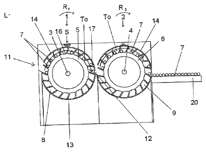
Fig. 1 shows two washing machines 1, 2 according to the invention which are
arranged next to
one another and are connected one behind the other in terms of their function.
Each of the
washing machines 1, 2 has a drum 5, 6 which is rotatable about an axis of
rotation 3, 4 oriented in
the longitudinal direction L. Each of the two drums 5, 6 is rotatable in the
clockwise direction and
also in the anticlockwise direction in Fig. 1. In Fig. 1, the two drums 5, 6
are each rotating in the
clockwise direction. The drums 5, 6 are driven by means of an electric motor
(not shown). The
direction of rotation is changeable.
The two washing machines 1, 2 shown in Fig. 1 are intended as a washing
station for elongate
profile sections which have been cut to length, in particular sawn to length,
from an elongate
profile, preferably an elongate metal profile, particularly preferably a long
metal tube.
After being cut to length, the cut-to-length tube sections 7 are subjected to
an after-treatment; in
particular the tube ends thereof are chamfered, brushed or the like. At the
end of the chain of
machining steps or even in an intermediate step, the tube sections 7 are also
washed by means of
the washing machines 1, 2 according to the invention.
Each of the two drums 1, 2 in Fig. I may have a size of up to a few metres in
the longitudinal
direction L. The two drums 5, 6 are concentric about their respective axis of
rotation 3, 4.
The first drum 5 along the machining path in Fig. I has 20 receiving areas 8
for in each case one
tube section 7 or in each case one bundle of tube sections 7. The second drum
6, which follows
the first drum 5 in the transport direction Ri, likewise has 20 receiving
areas 9.
Hereinbelow, the description of the first washing machine I also relates in a
corresponding
manner to the function of the second washing machine 2. =
The washing machine 1 has a receiving opening 11 and a discharge opening 12
located opposite
said receiving opening in relation to the axis of rotation 3. The receiving
opening 11 is formed
CA 2933743 2017-09-18
8
over substantially the entire longitudinal extent of the drum 5. The discharge
opening 12 is
likewise formed over the entire longitudinal extent of the drum 5.
In Fig. 1, the tube sections 7 are conveyed individually to the washing
machine 1 and are
individually received in the receiving areas 8 via the receiving opening 11.
To this end, the tube
sections 7 are conveyed parallel to the longitudinal direction L, by means of
a conveyor belt (not
shown) for example, to the washing machine 1 and then, upon reaching the
receiving opening 11,
automatically roll via a slope under the effect of gravity into a respective
receiving area 8.
The rotational movement of the washing machine 1 is clocked. Alter a receiving
area 8 has been
newly filled via the receiving opening 11, the drum 5 of the washing machine I
rotates through
one-twentieth of the full circumference, and the next free receiving area 8 is
made available to
receive the next tube section 7. Fig. 1 shows ten tube sections 7 which are
inserted in the first
washing machine 1. In each case one tube section 7 is arranged in a receiving
area 8. The drum 5
of the washing machine 1 is delimited by a trough 13 to approximately half of
its circumference
on its side facing towards the ground. On its side facing away from the
ground, the drum '5 is
covered by a cover 14 which is displaceable or pivotable back and forth along
the transport
direction RI. The displacement movement is illustrated by a double-headed
arrow. Like the
trough 13, the cover 14 extends over the entire longitudinal extent of the
drum 5.
The cover 14 extends along the circumference of the drum 5 by the sum of the
sizes of the
receiving opening 11 and discharge opening 12 in the circumferential direction
less than half of
the total circumferential length. On its two longitudinal sides running in the
longitudinal direction
L, the cover 14 is rectilinear so that the receiving opening 11 is formed as a
rectangular gap and
the discharge opening 12 is likewise formed as a rectangular gap. The heights
of the two gaps,
that is to say the size thereof, are adjustable along the circumferential
direction by displacing the
cover 14 back and forth along the circumferential direction.
The washing machine 1 according to the invention is suitable in particular for
washing stainless
steel tubes or generally tubes having an outer wall that is susceptible to
scratching, or for cleaning
CA 2933743 2017-09-18
9
tubes which most have no scratches on the outer wall, such as for example
exhaust tubes, chair
legs or the like, The transportation through the washing machine 1 is
particularly gentle.
The tube sections 7 conveyed to the first washing machine 1 in Fig. 1 by means
of a feed
conveyor (not shown) are spaced apart from one another and each roll
individually into an
assigned receiving area 8. During the rolling process, no scratching occurs to
the outer surfaces of
the tube, or at least the risk of scratching is considerably lower than when
the tubes are pushed
over a surface for example. Since the drum 5 in Fig. 1 rotates in the
clockwise direction, the tube
sections are conveyed along an upper transport path To from the receiving
opening 11 to the
discharge opening 12. During approximately the first half of the upper
transport path To, the tube
sections 7 lie in the lower, ground-facing, trailing and radially inner corner
of the respective
receiving area 8 until the receiving area 8 has reached an apex S of the upper
transport path To.
At that point, once the radial inner wall 16 of the receiving area 8 has
tilted from a positive into a
negative slope along the circumferential direction, the tube section 7 rolls
from the trailing inner
corner to the leading inner corner of the receiving area 8. During this gentle
rolling movement
along the inner wall 16 of the receiving area 8, no scratches are produced. In
the second section
of the upper transport path To, the tube section 7 remains in the radially
inner leading corner of
the receiving area 8 until the leading side wall 17, which delimits the
receiving areas 8 from one
another, slopes radially outwards and downwards with respect to the ground, so
that the tube
section 7 rolls radially outwards along the leading side wall 17 until the
tube section 7 butts
against the radial inner side of the cover 14, The cover 14 is displaced so
far forward in the
transport direction RI of the tube sections 7 that the discharge gap forming
the discharge opening
12, which is formed by the longitudinal edge of the lower trough 13 and the
longitudinal edge of
the cover 14, has a height which corresponds to the diameter of the tube,
preferably plus 10%,
preferably plus 15%. The tube section 7, which on the last part of the upper
transport path To is
arranged at the radially outer leading corner, formed by the leading side wall
17 and the cover 14,
falls out of the receiving area 8 only once the leading side wall 17 of the
receiving area 8 has
reached the height of the longitudinal edge of the trough 13.
If the cover 14 were not rotated far enough in the transport direction R1, the
tube section 7 would
roll out and fall out of the receiving area 8 too early, which might lead to
damage.
CA 2933743 2017-09-18
10
After the first washing operation in the first washing machine 1, the tube
section 7 is fed to a
second washing machine 2. During the transport along the upper transport path
To, the tube
sections 7 are first washed and then pre-dried. The receiving areas 8 are in
each case open at their
two end sides, so that a flow of water can flow in the longitudinal direction
L through each of the
s receiving areas 8 when the latter have reached a given position during
their rotational movement,
said flow of water freeing the tube section 7 inserted in the receiving area 8
of metal shavings and
the like. The washing means (not shown) is preferably arranged between the
receiving opening
II and the apex S. A first pre-drying device (not shown) is preferably
provided between the apex
S and the discharge opening 12 and blows an air flow through the receiving
area 8 respectively
arranged in front of it.
A corresponding structure applies to the second washing machine 2.
After the tube sections 7 have rolled out of the second washing machine 2,
they are conveyed
away from the second washing machine 2 on a conveyor device 20, Air nozzles
pointing in the
longitudinal direction L at the height of the tube sections 7 may be provided
along the conveyor
device 20, which nozzles blow hot air at a temperature of up to 300e through
the tube sections 7
and along the tube sections 7 in order to carry out final drying of the tube
sections 7.
Fig. 2 shows the double washing machine 1, 2 of Fig, 1 in its second mode of
operation. In this
case, the tube sections 7 are each transported not along an upper transport
path To but rather
along a lower transport path It, which runs between the axis of rotation 3, 4
and the ground. This
corresponds substantially to the conventional washing operation. However, the
washing machine
1, 2 according to the invention makes it possible to switch back and forth
between the washing
operation according to the invention and the conventional washing operation.
In this case, one
washing machine 1, 2 can use the upper transport path To and the other washing
machine 1, 2 can
use the lower transport path Tu. In the conventional washing operation shown
in Fig. 2, however,
it may be disadvantageous for some tube sections 7 that the tube sections
slide and are pushed
along the inner side of the trough 13 and do not roll, so that in this case,
at [east when metal
CA 2933743 2017-09-18
11
shavings are additionally present in the receiving area 8, scratches may occur
on the outer walls
of the tube sections 7.
List of references
washing machine
2 washing machine
3 axis of rotation
4 axis of rotation
5 drum
6 drum
7 tube sections
8 receiving area
9 receiving area
11 receiving opening
12 discharge opening
13 trough
14 cover
16 radial inner wall
17 leading side wall
20 conveyor device
longitudinal direction
apex
CA 2933743 2017-09-18
12
To upper transport path
Tu lower transport path
R1 transport direction
R2 transport direction
CA 2933743 2017-09-18