Note: Descriptions are shown in the official language in which they were submitted.
CA 02933756 2016-06-13
WO 2015/179787 PCT/US2015/032222
Box by Pin Perforating Gun System and Methods
Background
Generally, when completing a subterranean well for the production of fluids,
minerals, or
gases from underground reservoirs, several types of tubulars are placed
downhole as part of the
drilling, exploration, and completions process. These tubulars can include
casing, tubing, pipes,
liners, and devices conveyed downhole by tubulars of various types. Each well
is unique, so
combinations of different tubulars may be lowered into a well for a multitude
of purposes.
A subsurface or subterranean well transits one or more formations. The
formation is a
body of rock or strata that contains one or more compositions. The formation
is treated as a
continuous body. Within the formation hydrocarbon deposits may exist.
Typically a wellbore
will be drilled from a surface location, placing a hole into a formation of
interest. Completion
equipment will be put into place, including casing, tubing, and other downhole
equipment as
needed. Perforating the casing and the formation with a perforating gun is a
well known method
in the art for accessing hydrocarbon deposits within a formation from a
wellbore.
Explosively perforating the formation using a shaped charge is a widely known
method
for completing an oil well. A shaped charge is a term of art for a device that
when detonated
generates a focused explosive output. This is achieved in part by the geometry
of the explosive in
conjunction with an adjacent liner. Generally, a shaped charge includes a
metal case that contains
an explosive material with a concave shape, which has a thin metal liner on
the inner surface.
Many materials arc used for the liner; some of the more common metals include
brass, copper,
tungsten, and lead. When the explosive detonates the liner metal is compressed
into a super-
heated, super pressurized jet that can penetrate metal, concrete, and rock.
Perforating charges are
typically used in groups. These groups of perforating charges are typically
held together in an
assembly called a perforating gun. Perforating guns come in many styles, such
as strip guns,
capsule guns, port plug guns, and expendable hollow carrier guns.
Perforating charges are typically detonated by detonating cord in proximity to
a priming
hole at the apex of each charge case. Typically, the detonating cord
terminates proximate to the
ends of the perforating gun. In this arrangement, a detonator at one end of
the perforating gun
can detonate all of the perforating charges in the gun and continue a
ballistic transfer to the
CA 02933756 2016-06-13
WO 2015/179787 PCT/US2015/032222
opposite end of the gun. In this fashion, numerous perforating guns can be
connected end to end
with a single detonator detonating all of them.
The detonating cord is typically detonated by a detonator triggered by a
firing head. The
firing head can be actuated in many ways, including but not limited to
electronically,
hydraulically, and mechanically.
Expendable hollow carrier perforating guns are typically manufactured from
standard
sizes of steel pipe with a box end having internaUfemale threads at each end.
Pin ended adapters,
or subs, having male/external threads are threaded one or both ends of the
gun. These subs can
connect perforating guns together, connect perforating guns to other tools
such as setting tools
and collar locators, and connect firing heads to perforating guns. Subs often
house electronic,
mechanical, or ballistic components used to activate or otherwise control
perforating guns and
other components.
Perforating guns typically have a cylindrical gun body and a charge tube, or
loading tube
that holds the perforating charges. The gun body typically is composed of
metal and is
cylindrical in shape. Within a typical gun tube is a charge holder designed to
hold the shaped
charges. Charge holders can be formed as tubes, strips, or chains. The charge
holder will contain
cutouts called charge holes to house the shaped charges.
It is generally preferable to reduce the total length of any tools to be
introduced into a
wellbore. Among other potential benefits, reduced tool length reduces the
length of the
lubricator necessary to introduce the tools into a wellbore under pressure.
Additionally, reduced
tool length is also desirable to accommodate turns in a highly deviated or
horizontal well. It is
also generally preferable to reduce the tool assembly that must be performed
at the well site
because the well site is often a harsh environment with numerous distractions
and demands on
the workers on site.
Currently, perforating guns are often assembled and loaded at a service
company shop,
transported to the well site, and then armed before they are deployed into a
well. Sometimes
perforating guns are assembled and armed at the well site. Because the service
company shop
often employs a single gun loader, maintaining close control on the gun
assembly/loading
procedures can become difficult. Accordingly, quality control on the
assembled/loaded guns
may be improved by reducing the amount of assembly necessary at the service
company shop.
2
CA 02933756 2016-06-13
WO 2015/179787 PCT/US2015/032222
Many perforating guns are electrically activated. This requires electrical
wiring to at
least the firing head for the perforating gun. In many cases, perforating guns
are run into the
well in strings where guns are activated either singly or in groups, often
separate from the
activation of other tools in the string, such as setting tools. In these
cases, electrical
communication must be able to pass through one perforating gun to other tools
in the string.
Typically, this involves threading at least one wire through the interior of
the perforating gun and
using the gun body as a ground wire.
When typical a perforating gun is assembled/loaded either at the well site or
at a service
company shop, there is risk of incorrect assembly or damage to electrical
wiring or other
components that may cause the perforating gun or other tools to fail to fire
or fail to function
appropriately. For example, the threading of a pass-through wire through the
gun body or charge
holder presents numerous opportunities for the insulation of the wire to be
stripped on sharp
metal edges resulting in shorts in the communications circuit. Accordingly,
there is a need for a
system that eliminates the need to run a wire through a perforating gun body.
Typically, perforating guns and other tools are connected to each other
electrically at the
well site. This requires that a worker bring the guns or tools close together
and then manually
make a connection with one or more wires. This requires time and manpower at
the well site and
introduces the possibility of injury or assembly error. Accordingly, there is
a need for a system
that eliminates the requirement for workers to make wire connections between
perforating guns
or tools at the well site.
As discussed above, perforating guns and other tools arc often connected with
subs that
also house related electronic and/or ballistic components. In order to
eliminate these subs, a
system is needed to house these electrical and ballistic components inside of
perforating guns or
other tools in an interchangeable and modular way. Additionally, current
perforating guns
typically have the same diameter and female threads on both ends. In order to
eliminate the
subs, a perforating gun system that provides male threads on one end of the
gun and female
threads on the other is needed.
3
CA 02933756 2016-06-13
WO 2015/179787 PCT/US2015/032222
Summary of examples of the invention
One embodiment to enable thin-walled perforating guns to be threaded directly
together
is a gun body that is swaged down to a smaller diameter on one end than the
other. The smaller
diameter end of the gun has male threads that are adapted to engage
corresponding female
threads on the larger end of a second perforating gun that has substantially
the same outer
diameter.
Another embodiment to enable thin-walled perforating guns to be threaded
directly
together is to use certain premium thread configurations that provide
sufficient tensile strength in
the joint despite relatively shallow thread depth. In this embodiment, both
ends of the gun body
have substantially the same outer diameter before machining to cut the
threads. Male threads are
placed on one end of the gun that are adapted to engage corresponding female
threads on the
other end.
Another embodiment to enable thin-walled perforating guns to be threaded
directly
together is a fitting welded onto one end of the gun body where the fitting
has male threads that
are adapted to engage corresponding female threads on the larger end of a
second perforating
gun that has substantially the same outer diameter.
One embodiment to enable electrical communication through a perforating gun
without
passing a wire though the gun body is to use metallic shaped charge holder as
the pass-through
conductor. This embodiment requires insulating the charge holder from the gun
body. This
insulation can be achieved using of one or more of: insulating end caps on the
charge holder;
insulating charge retainers on the apex end of the shaped charges; insulating
caps on the open
end of the shaped charges; an insulating sheath over the charge holder; an
insulating tube in the
annulus between the charge holder and the gun body; insulating coating on the
charge tube;
insulating coating on the inner surface of the gun body.
Another embodiment to enable electrical communication through a perforating
gun
without passing a wire though the gun body is to include a conductor integral
with the detonating
cord.
One embodiment to eliminate the need to make wire connections between
perforating
guns is to provide a receptacle or resilient connector that engages and
maintains electrical contact
as two perforating guns are threaded together.
4
CA 02933756 2016-06-13
WO 2015/179787 PCT/US2015/032222
One embodiment to house electrical and ballistic components in the perforating
gun is to
house the electrical and ballistic components in a cartridge inside the gun
body. In a further
embodiment, the cartridge fits inside an adapter inside the gun body so that a
single cartridge
diameter can be used in a variety of diameters of perforating gun bodies.
One example method of perforating a well includes the steps of: loading a
first
perforating gun with perforating charges and detonating cord; inserting a
cartridge holding a
detonator into the perforating gun; assembling the perforating gun in a tool
string; conveying the
tool string into the well; detonating the perforating charges. In a further
example method of
perforating a well the cartridge has at least one electrical contact proximate
each end. In a
further example method of perforating a well at least one of the electrical
contacts of the
cartridge is resiliently biased. In a further example method of perforating a
well at least one of
the electrical contacts of the cartridge is a compression spring. In a further
example method of
perforating a well at least one of the electrical contacts of the cartridge is
a pin adapted to engage
a socket. In a further example method of perforating a well the socket is
resiliently biased
toward the pin. In a further example method of perforating a well the
cartridge also holds a
switch electrically connected to the detonator. A further example method of
perforating a well
includes the step of conveying the first perforating gun to a well site after
loading the first
perforating gun with perforating charges and detonating cord. A further
example method of
perforating a well includes the step of conveying the first perforating gun to
a well site after
inserting the cartridge containing the detonator into the perforating gun. A
further example
method of perforating a well includes the step of connecting the first
perforating gun to a second
perforating gun by threading the body of the first perforating gun directly
into the body of the
second perforating gun.
One example method of manufacturing a perforating gun body includes the steps
of
receiving a metallic tube of substantially constant diameter from a first end
to a second end;
forming external threads in the first end; and forming internal threads in the
second end; wherein
the internal threads are adapted to engage the external threads. A further
example method of
manufacturing a perforating gun body includes the step of swaging down the
diameter of the first
end before forming the external threads. A further example method of
manufacturing a
perforating gun body includes the step of swaging up the diameter of the
second end before
CA 02933756 2016-06-13
WO 2015/179787 PCT/US2015/032222
forming the internal threads. In a further example method of manufacturing a
perforating gun
body the internal and external threads are self-sealing threads.
One example method of manufacturing a perforating gun body includes the steps
of:
receiving a metallic tube of substantially constant diameter from a first end
to a second end;
affixing a fitting to the first end; forming external threads in the fitting;
and forming internal
threads in the second end; where the internal threads are adapted to engage
the external threads.
In a further example method of manufacturing a perforating gun body the
fitting is affixed to the
first end by welding. In a further example method of manufacturing a
perforating gun body the
fitting is affixed to the first end by friction welding.
One example perforating gun system includes: a first gun body having external
threads at
a first end and internal threads at a second end; and a cartridge holding a
detonator. A further
example perforating gun system includes a switch electrically connected to the
detonator. In a
further example perforating gun system the cartridge holds the switch. In a
further example
perforating gun system the cartridge is adapted to be inserted and removed
from the perforating
gun as a unit. A further example perforating gun system includes a shaped
charge loading tube
having an upper end and a lower end; where the cartridge has an electrical
contact proximate to
the detonator and the lower end of the loading tube has an electrical contact
adapted to contact
the electrical contact proximate to the detonator. A further example
perforating gun system
includes at least one insulator between the shaped charge loading tube and the
gun body. A
further example perforating gun system includes an upper end fitting on the
upper end of the
shaped charge loading tube; and a lower end fitting on the lower end of the
shaped charge
loading tube. A further example perforating gun system includes an upper
insulating cap on
upper end fitting; a lower insulating cap on lower end fitting; and wherein
the upper and lower
end fittings are conductive. In a further example perforating gun system the
at least one insulator
comprises an insulating fitting on an apex end of a plurality of shaped
charges. In a further
example perforating gun system the at least one insulator comprises an
insulating fitting on an
open end of a plurality of shaped charges. In a further example perforating
gun system the at
least one insulator comprises an insulating sleeve over the shaped charge
loading tube. In a
further example perforating gun system the cartridge has at least one
electrical contact at each
end. In a further example perforating gun system at least one of the
electrical contacts of the
cartridge is resiliently biased. In a further example perforating gun system
at least one of the
6
CA 02933756 2016-06-13
WO 2015/179787 PCT/US2015/032222
electrical contacts of the cartridge is a compression spring. In a further
example perforating gun
system at least one of the electrical contacts of the cartridge is a pin
adapted to engage a socket
in the upper end fitting of the loading tube. In a further example perforating
gun system the
socket is resiliently biased toward the pin. In a further example perforating
gun system the
cartridge has at least one electrical contact at each end.
One example perforating gun system includes: a first metallic gun body; a
first shaped
charge loading tube; a first insulator between the gun body and the loading
tube; and a cartridge
holding a detonator and a switch; wherein the detonator is electrically
connected to the switch.
In a further example perforating gun system the cartridge is adapted to be
inserted and removed
from the perforating gun as a unit. A further example perforating gun system
includes a shaped
charge loading tube having an upper end and a lower end; wherein the cartridge
has an electrical
contact proximate to the detonator and the lower end of the loading tube has
an electrical contact
adapted to contact the electrical contact proximate to the detonator. A
further example
perforating gun system includes an upper end fitting on the upper end of the
shaped charge
loading tube; and a lower end fitting on the lower end of the shaped charge
loading tube. A
further example perforating gun system includes an upper insulating cap on
upper end fitting;
and a lower insulating cap on lower end fitting; wherein the upper and lower
end fittings are
conductive. In a further example perforating gun system the at least one
insulator comprises an
insulating fitting on an apex end of a plurality of shaped charges. In a
further example
perforating gun system the at least one insulator comprises an insulating
fitting on an open end of
a plurality of shaped charges. In a further example perforating gun system the
at least one
insulator comprises an insulating sleeve over the shaped charge loading tube.
In a further
example perforating gun system the cartridge has at least one electrical
contact at each end. In a
further example perforating gun system at least one of the electrical contacts
of the cartridge is
resiliently biased. In a further example perforating gun system at least one
of the electrical
contacts of the cartridge is a compression spring. In a further example
perforating gun system at
least one of the electrical contacts of the cartridge is a pin adapted to
engage a socket in the
upper end fitting of the loading tube. In a further example perforating gun
system the socket is
resiliently biased toward the pin.
7
CA 02933756 2016-06-13
WO 2015/179787 PCT/US2015/032222
One example perforating gun body includes: a substantially cylindrical tube;
an upper
end of the tube having internal threads; a lower end of the tube having
external threads; wherein
the lower end has a smaller diameter than the upper end. A further example
perforating gun
body includes internal threads in the lower end. A further example perforating
gun body
includes an alignment slot in an inner wall adapted to engage an alignment tab
on a shaped
charge loading tube. A further example perforating gun body includes an
alignment slot in an
inner wall adapted to engage an alignment tab on a shaped charge holder.
One example baffle for adapting a cartridge to a perforating gun includes a
substantially
cylindrical body, a cavity in the body adapted to receive a cartridge,
internal threads in the cavity
adapted to engage external threads on the cartridge, and external threads
adapted to engage
internal threads on a perforating gun body. A further example baffle for
adapting a cartridge to a
perforating gun includes tool flats adapted to allow a tool to rotate the
baffle.
One example cartridge for use in a perforating gun includes: a cartridge body
having an
upper end and a lower end; a detonator proximate the upper end; a switch
electrically connected
to the detonator; a first electrical contact proximate the lower end; a first
electrical contact
proximate the upper end; where the first electrical contacts proximate the
lower end and upper
end are electrically connected to the switch. In a further example cartridge
for use in a
perforating gun the first electrical contact proximate the lower end is
resiliently biased away
from the upper end. In a further example cartridge for use in a perforating
gun the first electrical
contact proximate the upper end is resiliently biased away from the lower end.
A further
example cartridge for use in a perforating gun includes a second electrical
contact proximate the
lower end and electrically connected to the switch. In a further example
cartridge for use in a
perforating gun the second electrical contact proximate the lower end is
resiliently biased away
from the upper end. In a further example cartridge for use in a perforating
gun the first electrical
contact proximate the upper end comprises a conductive end cap. In a further
example cartridge
for use in a perforating gun the first electrical contact proximate the upper
end further comprises
a compression spring. In a further example cartridge for use in a perforating
gun the first contact
proximate the lower end comprises an insulated feed-through pin. A further
example cartridge
for use in a perforating gun includes external threads adapted to engage
internal threads on a
baffle. A further example cartridge for use in a perforating gun includes
external threads adapted
to engage internal threads on a perforating gun body.
CA 02933756 2016-06-13
WO 2015/179787 PCT/US2015/032222
One example shaped charge loading tube for use in a perforating gun includes:
a
conductive charge holder; an upper end fitting having a diameter larger than
the diameter or
width of the charge holder; a lower end fitting having a diameter larger than
the diameter or
width of the charge holder; wherein the upper end fitting and lower end
fitting each comprise an
insulating material about their outer circumference. In a further example
shaped charge loading
tube the upper and lower end fitting each further comprises a conductive puck
that is electrically
connected to the charge holder. In a further example shaped charge loading
tube the upper end
fitting further comprises an electrical contact that is electrically connected
to the charge holder.
In a further example shaped charge loading tube the upper end fitting further
comprises an
electrical contact that is electrically connected to the charge holder. In a
further example shaped
charge loading tube the upper end fitting further comprises an alignment tab
adapted to engage
an alignment slot on an interior wall of a perforating gun body. In a further
example shaped
charge loading tube the upper end fitting further comprises an insulating cap.
In a further
example shaped charge loading tube the upper end fitting further comprises
conductive puck. In
a further example shaped charge loading tube the conductive puck further
comprises an
alignment slot. In a further example shaped charge loading tube the upper
insulating cap further
comprises an external alignment tab adapted to engage an alignment slot in a
perforating gun
body and an internal alignment tab adapted to engage an alignment slot in the
conductive puck.
In a further example shaped charge loading tube the upper end fitting further
comprises an
alignment tab adapted to engage an alignment slot on an interior wall of a
perforating gun body.
One example shaped charge loading tube end fitting includes: a body having a
central
axis; a detonator bore coaxial with the central axis adapted to accept a
detonator; a detonating
cord bore with an axis at an angle greater than zero from the central axis;
wherein the detonating
cord bore is adapted to accept detonating cord and intersects the detonator
bore. In a further
example shaped charge loading tube end fitting the axis of the detonating cord
bore is offset from
the central axis of the body by approximately 35 degrees.
9
. .
In a broad aspect, the present invention pertains to a performing gun system
comprising a first
gun body having external threads at a first end, and internal threads at a
second end. There is a shaped
charge loading tube, and a cartridge holding a detonator, and there is at
least one insulator between the
shaped loading tube and the gun body. The cartridge has at least one
electrical contact at each end, and at
least one of the electrical contacts of the cartridge is resiliently biased,
by a compression spring. The
method further comprehends a method of perforating a well in using the gun
system noted above.
In a further aspect, the present invention embodies a perforating gun system
comprising a first
gun body having external threads at a first end and internal threads at a
second end, a cartridge holding a
detonator, and a shaped charge loading tube having an upper end and a lower
end. There is an upper end
fitting on the upper end of the shaped charge loading tube, a lower end
fitting on the lower end of the
shaped charge loading tube, an upper insulating cap on the upper end fitting,
and a lower insulating cap
on the lower end fitting. The upper and the lower end fittings are conductive,
the cartridge has an
electrical contact proximate to the detonator, and the lower end of the
loading tube has an electrical
contact adapted to contact the electrical contact proximate to the detonator.
In a still further aspect, the present invention provides a perforating gun
system comprising a first
gun body having external threads at a first end and internal threads at a
second end, a cartridge holding a
detonator, a switch electrically connected to the detonator, and there is at
least one insulator between the
shaped charge loading tube and the gun body. The cartridge has at least one
electrical contact at each
end, and at least one of the electrical contacts of the cartridge is
resiliently biased.
Yet further, the present invention provides a perforating gun system
comprising a first gun body
having external threads at a first end and internal threads at a second end.
There is provided a cartridge
holding a detonator, a switch electrically connected to the detonator, and at
least one insulator between
the shaped charge loading tube and the gun body. The cartridge has at least
one electrical contact at each
end, and at least one of the electrical contacts of the cartridge is a pin
adapted to engage a socket in the
upper end fitting of the loading tube.
9a
CA 2933756 2019-10-30
Brief Description of the Drawings
Figure 1 is a cross-sectional view of an example embodiment of a perforating
gun
system.
Figure 2 is an end view of the example embodiment of a perforating gun system
shown in
Figure 1.
Figure 3 is an end view of the top end fitting assembly from the example
embodiment of
a perforating gun system in Figure 1.
Figure 4 is a cross-sectional view of the top end fitting assembly from the
example
embodiment of a perforating gun system in Figure 1.
Figure 5 is a cross-sectional view of the male end of one perforating gun
mated to the
female end of another perforating gun in the example embodiment of a
perforating gun system
shown in Figure 1.
Figure 6 is a cross sectional view of a plug-shoot adapter of the example
embodiment of a
perforating gun system shown in Figure 1.
Figure 7 is an exploded perspective view of an example embodiment a
perforating gun
assembly.
Figure 8A is a perspective view of the baffle of the example embodiment of a
perforating
gun system shown in Figure 1.
Figure 8B is a side view of the baffle shown in Figure A.
Figure 8C is an end view of the baffle shown in Figure 8A.
Figure 8D is an end view of the baffle shown in Figure 8A.
Figure 8E is a cross-sectional view of the baffle shown in Figure 8A.
Figure 9A is a side view of an example embodiment of a perforating gun body.
Figure 9B is an end view of the example embodiment of a perforating gun body
shown in
Figure 9A.
Figure 9C is an end view of the example embodiment of a perforating gun body
shown in
Figure 9A.
Figure 9D is a cross-sectional view of the example embodiment of a perforating
gun body
shown in Figure 9A.
Figure 10 is an exploded perspective view of an example embodiment of a shaped
charge
loading tube assembly.
CA 2933756 2018-05-29
CA 02933756 2016-06-13
WO 2015/179787 PCT/US2015/032222
Figure 11A is a side view of the example embodiment of a charge tube component
shown
in Figure 10.
Figure 11B is a side view of the example embodiment of a charge tube component
shown
in Figure 10.
Figure 11C is a side view of the example embodiment of a charge tube component
shown
in Figure 10.
Figure 12A is a perspective view of the apex end of an example embodiment of a
shaped
charge case.
Figure 12B is a view of the apex end of an example embodiment of a shaped
charge case.
Figure 12C is a cross-sectional view of an example embodiment of a shaped
charge case.
Figure 12D is a cross-sectional view of the apex end of an example embodiment
of a
shaped charge case.
Figure 13A is a perspective view of an example embodiment of a shaped charge
retainer.
Figure 13B is a top view of an example embodiment of a shaped charge retainer.
Figure 13C is a top view of an example embodiment of a shaped charge retainer.
Figure 13D is a side view of an example embodiment of a shaped charge
retainer.
Figure 13E is a bottom view of an example embodiment of a shaped charge
retainer.
Figure 14A is an end view of an example embodiment of a top end fitting
assembly of a
perforating gun system.
Figure 14B is a cross-sectional view of an example embodiment of a top end
fitting
assembly of a perforating gun system.
Figure 15 is a cross-sectional view of an example embodiment of a bottom end
fitting
assembly of a perforating gun system.
Figure 16A is an end view of an example embodiment of a top end fitting
assembly of a
perforating gun system.
Figure 16B is a cross-sectional view of an example embodiment of a top end
fitting
assembly of a perforating gun system.
Figure 17 is a cross-sectional view of an example embodiment of a bottom end
fitting
assembly of a perforating gun system.
Figure 18A is a perspective view of an example embodiment of a feed thru puck
of the
perforating gun system shown in Figure 1.
11
Figure 18B is a side view of an example embodiment of a feed thru puck of the
perforating gun system in Figure 1.
Figure 18C is a cross-sectional view of an example embodiment of a feed thru
puck of
the perforating gun system shown in Figure 1.
Figure 18D is an end view of an example embodiment of a feed thru puck of the
perforating gun system shown in Figure 1.
Figure 18E is an end view of an example embodiment of a feed thru puck of the
perforating gun system shown in Figure 1.
Figure 19A is a perspective view of an example embodiment of a top insulation
cap of
the perforating gun system shown in Figure 1.
Figure 19B is a side view of an example embodiment of a top insulation cap of
the
perforating gun system shown in Figure 1.
Figure 19C is a cross-sectional view of an example embodiment of a top
insulation cap
of the perforating gun system shown in Figure 1.
Figure 19D is an end view of an example embodiment of a top insulation cap of
the
perforating gun system shown in Figure 1.
Figure 19E is an end view of an example embodiment of a top insulation cap of
the
perforating gun system shown in Figure 1.
Figure 19F is a detail from the cross-section view of an example embodiment of
a top
insulation cap of the perforating gun system shown in Figure 19C.
Figure 20A is a perspective view of an example embodiment of a deto transfer
puck of
a perforating gun system.
Figure 20B is a side view of an example embodiment of a deto transfer puck of
a
perforating gun system.
Figure 20C is a side view of an example embodiment of a deto transfer puck of
a
perforating gun system.
Figure 20D is a cross-sectional view of an example embodiment of a deto
transfer puck
of the perforating gun system of Figure 1.
Figure 20E is a cross-sectional view of an example embodiment of a deto
transfer puck
of a perforating gun system.
Figure 20F is an end view of an example embodiment of a deto transfer puck of
a
perforating gun system.
12
CA 2933756 2017-11-23
CA 02933756 2016-06-13
WO 2015/179787 PCT/US2015/032222
Figure 21A is a perspective view of an example embodiment of a bottom
insulation cap
of the perforating gun system shown in Figure 1.
Figure 21B is a side view of an example embodiment of a bottom insulation cap
of the
perforating gun system shown in Figure 1.
Figure 21C is a cross-sectional view of an example embodiment of a bottom
insulation
cap of the perforating gun system shown in Figure 1.
Figure 21D is an end view of an example embodiment of a bottom insulation cap
of the
perforating gun system shown in Figure 1.
Figure 22 is an exploded perspective view of an example embodiment of a
cartridge
assembly.
Figure 23A is a perspective view of an example embodiment of a cartridge end
cap of the
cartridge shown in Figure 22.
Figure 23B is a side view of an example embodiment of a cartridge end cap of
the
cartridge shown in Figure 22.
Figure 23C is a cross-sectional view of an example embodiment of a cartridge
end cap of
the cartridge shown in Figure 22.
Figure 23D is an end view of an example embodiment of a cartridge end cap of
the
cartridge shown in Figure 22.
Figure 23E is an end view of an example embodiment of a cartridge end cap of
the
cartridge shown in Figure 22.
Figure 24 is a perspective view of an example embodiment of a contact spring
of the
cartridge shown in Figure 22.
Figure 25A is a perspective view of an example embodiment of a plastic
cartridge body
top of the cartridge shown in Figure 22.
Figure 25B is a top view of an example embodiment of a plastic cartridge body
top of the
cartridge shown in Figure 22.
Figure 25C is a cross-sectional view of an example embodiment of a plastic
cartridge
body top of thc cartridge shown in Figure 22.
Figure 25D is an end view of an example embodiment of a plastic cartridge body
top of
the cartridge shown in Figure 22.
13
õ
Figure 25E is an end view of an example embodiment of a plastic cartridge body
top of
the cartridge shown in Figure 22.
Figure 25F is a cross-sectional view of an example embodiment of a plastic
cartridge
body top of the cartridge shown in Figure 22.
Figure 26A is a perspective view of an example embodiment of a plastic
cartridge body
bottom of the cartridge shown in Figure 22.
Figure 26B is a top view of an example embodiment of a plastic cartridge body
bottom of
the cartridge shown in Figure 22.
Figure 26C is a cross-sectional view of an example embodiment of a plastic
cartridge
body bottom of the cartridge shown in Figure 22.
Figure 26D is an end view of an example embodiment of a plastic cartridge body
bottom
of the cartridge shown in Figure 22.
Figure 26E is an end view of an example embodiment of a plastic cartridge body
bottom
of the cartridge shown in Figure 22.
Figure 26F is a cross-sectional view of an example embodiment of a plastic
cartridge
body bottom of the cartridge shown in Figure 22.
Figure 26G is an axial cross-sectional view of an example embodiment of a
plastic
cartridge body bottom of the cartridge as indicated in Figure 26C.
Figure 27A is a perspective view of an example embodiment of a grounding cap
of the
cartridge shown in Figure 22.
Figure 27B is an end view of an example embodiment of a grounding cap of the
cartridge
shown in Figure 22.
Figure 27C is a cross-sectional view of an example embodiment of a grounding
cap of
the cartridge shown in Figure 22.
Figure 27D is an end view of an example embodiment of a grounding cap of the
cartridge
shown in Figure 22.
Figure 28 is a perspective view of an example embodiment of a ground spring of
the
cartridge shown in Figure 22.
Figure 29A is a perspective view of an example embodiment of a fed through pin
assembly of the cartridge shown in Figure 22.
14
CA 2933756 2018-07-10
CA 02933756 2016-06-13
WO 2015/179787 PCT/US2015/032222
Figure 29B is an end view of an example embodiment of a feed through pin
assembly of
the cartridge shown in Figure 22.
Figure 29C is a cross-sectional view of an example embodiment of feed through
pin
assembly of the cartridge shown in Figure 22.
Figure 30A is a perspective view of an example embodiment of a bulkhead
retainer of the
cartridge shown in Figure 22.
Figure 30B is an end view of an example embodiment of a bulkhead retainer of
the
cartridge shown in Figure 22.
Figure 30C is a cross-sectional view of an example embodiment of a bulkhead
retainer of
the cartridge shown in Figure 22.
Figure 30D is an end view of an example embodiment of a bulkhead retainer of
the
cartridge shown in Figure 22.
Figure 30E is an end view of an example embodiment of a bulkhead retainer of
the
cartridge shown in Figure 22.
Figure 31 is an exploded perspective view of an example embodiment of a plug
and shoot
adapter assembly.
Figure 32A is a perspective view of an example embodiment of a plug and shoot
body of
the plug and shoot adapter assembly shown in Figure 31.
Figure 32B is an end view of an example embodiment of a plug and shoot body of
the
plug and shoot adapter assembly shown in Figure 31.
Figure 32C is a cross-sectional view of an example embodiment of a plug and
shoot body
of the plug and shoot adapter assembly shown in Figure 31.
Figure 33A is a perspective view of an example embodiment of an igniter holder
of the
plug and shoot adapter assembly shown in Figure 31.
Figure 33B is an end view of an example embodiment of an igniter holder of the
plug and
shoot adapter assembly shown in Figure 31.
Figure 33C is a cross-sectional view of an example embodiment of an igniter
holder of
the plug and shoot adapter assembly shown in Figure 31.
Figure 33D is an end view of an example embodiment of an igniter holder of the
plug and
shoot adapter assembly shown in Figure 31.
CA 02933756 2016-06-13
WO 2015/179787 PCT/US2015/032222
Figure 34A is a perspective view of an example embodiment of an igniter of the
plug and
shoot adapter assembly shown in Figure 31.
Figure 34B is a side view of an example embodiment of an igniter of the plug
and shoot
adapter assembly shown in Figure 31.
Figure 35A is a perspective view of an example embodiment of a plug and shoot
feed
through of the plug and shoot adapter assembly shown in Figure 31.
Figure 35B is an end view of an example embodiment of a plug and shoot feed
through
of the plug and shoot adapter assembly shown in Figure 31.
Figure 35C is a cross-sectional view of an example embodiment of a plug and
shoot feed
through of the plug and shoot adapter assembly shown in Figure 31.
Figure 35D is an end view of an example embodiment of a plug and shoot feed
through
of the plug and shoot adapter assembly shown in Figure 31.
Figure 36 is an exploded perspective view of an example embodiment of a plug
and shoot
cartridge assembly.
Figure 37A is a perspective view of an example embodiment of a plug and shoot
feed
through receptacle of the plug and shoot adapter assembly shown in Figure 31.
Figure 37B is an end view of an example embodiment of a plug and shoot feed
through
receptacle of the plug and shoot adapter assembly shown in Figure 31.
Figure 37C is a cross-sectional view of an example embodiment of a plug and
shoot feed
through receptacle of the plug and shoot adapter assembly shown in Figure 31.
Figure 38 is an exploded perspective view of an example embodiment of a top
gun
adapter sub assembly.
Figure 39 is a cross-sectional view of an example embodiment of a perforating
gun
system.
Figure 40 is a cross-sectional view of the male end of one perforating gun
mated to the
female end of another perforating gun in the example embodiment of a
perforating gun system
shown in Figure 39.
Figure 41 is a cross-sectional view of an example embodiment of a perforating
gun
system.
16
CA 02933756 2016-06-13
WO 2015/179787 PCT/US2015/032222
Figure 42 is a cross-sectional view of the male end of one perforating gun
mated to the
female end of another perforating gun in the example embodiment of a
perforating gun system
shown in Figure 41.
Figure 43 is a cross-sectional view of an example embodiment of a perforating
gun
system.
Figure 44 is a cross-sectional view of the male end of one perforating gun
mated to the
female end of another perforating gun in the example embodiment of a
perforating gun system
shown in Figure 43.
17
Detailed Description
Directional and orientation terms such as upper, lower, top, and bottom are
used in this
description for convenience and clarity in describing the features of
components. However,
those terms are not inherently associated with terrestrial concepts of up and
down or top and
bottom as the described components might be used in a well.
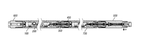
Figure 1 illustrates one example embodiment of a perforating gun system.
Figure 1
shows a top gun adapter sub assembly 600, a first perforating gun 100, a
second perforating gun
700, and a plug and shoot adapter 500.
Figure 7 shows an exploded view of example perforating gun 100. The
perforating gun
100 includes a shaped charge loading tube assembly 200, a cartridge 300, and a
baffle 400.
Perforating gun 100 includes gun body 130. Figures 9A, 9B, 9C, and 9D show an
example
embodiment of gun body 130. Gun body 130 includes a male end 110 and a- female
end 120.
Male end 110 has an external diameter 115, a first internal diameter 113, and
a second larger
internal diameter 114. Female end 120 has an external diameter 124, a first
internal diameter
123, and a second larger internal diameter 125. Male end 110 also has o-ring
grooves 112. Male
end 110 also includes internal threads 116 for engaging corresponding external
threads 431 on
baffle 400. Corresponding threads are understood to be designed and adapted to
engage and
affix to one another, for example, male and female threads of the same design
would correspond
to each other because they are adapted to engage and affix to one another.
Corresponding
threads may not always actually engage and affix to one another, for example,
threads on
opposite ends of a perforating gun may be adapted to engage each other, but in
practice actually
engage threads on other similar or matching perforating guns. Gun body 130 has
o-ring grooves
112 housing o-rings to provide a fluid pressure seal between one gun body an
another gun body
or other tool string component. Gun body 130 can be formed from a standard
thin-walled tubing
material by swaging male end 110 down in diameter and then machining
additional features,
such as threaded sections 121, 111, and o-ring grooves 112. The swaging
process allows the
material of gun body 130 to maintain desired strength from thin-walled tubing
when reducing the
diameter to allow corresponding male threads 111 and female threads 121 on
opposite ends of
gun body 130. Alternatively, a fitting can be welded onto one end of a gun
body to enable male
threads 111, o-ring grooves 112, first internal diameter 113 and second
internal diameter 114 to
be formed in the fitting. Those features can be formed either before or after
welding the fitting
18
CA 2933756 2019-01-31
=
onto gun body 130. A welded fitting example is shown in Figures 43 and 44.
Male end 110 has
a smaller internal diameter 113 and external diameter 115 than internal;
diameter 123 and
external diameter 124 of female end 120. Gun body 130 has scallops 131
corresponding to the
locations of shaped charges 270. Gun body 130 has an alignment slot 122 in its
inner surface to
engage alignment tab 211 top insulation cap 210 of loading tube assembly 200.
Loading tube
assembly 200 need not necessarily have a tubular shape.
Alternatively, gun body 130 may be formed with male threads and female threads
on
ends of substantially the same diameter. Certain threads designs may be able
to maintain needed
strength when cut into the timer and outer surfaces of standard thin-walled
tubing. For example,
the following premium threads may be used: Tenaris (all versions), CS Hydril,
Full Hole (drill
pipe), MT, AMT, AMMT, PAC, AMERICAN OPEN HOLE, various HUGHES thread
configurations, BTS-8, BTS-6, BTS-4, ECHO-F4, ECHO-SS, BFJ, BNFJ, SBFJP,
Drillco SSDS
and other Drillco threads, THE NU THREADS, NU 8RD, NU I ORD, SEAL-LOCK, and
WEDGE-LOCK. Alternatively, gun body 130 could be formed by swaging up one end
to
accommodate female threads corresponding to made threads on the original
diameter end.
The following thread types can eb used for various aspects of the disclosed
perforating
gun systems and components: TPI, GO Acme, SIE, Acme Thread, Stub Acme Thread,
Molded
Thread, Formed Thread, Premium Thread, Flush Joint Thread, Semi-Flush joint
Thread, API
Thread, EUE/Round Thread, Tapered Thread, V-thread, J-Latch, Breech Lock,
Tenaris (all
versions), CS Hydril, Full Hole (drill pipe), MT, AMT, AMMT, PAC, AMERICAN
OPEN
HOLE, various HUGHES thread configurations, BTS-8, BTS-6, BTS-4, ECHO-F4, ECHO-
SS,
BFJ, BNFJ, SBFJP, Drillco SSDS and other Drillco threads, THE NU THREADS, NU
8RD, NU
1ORD, SEAL-LOCK, and WEDGE-LOCK.
Additionally, double or triple lead versions of the above threads bay also be
used for
faster make-up.
Figures 8A, 8B, 8C, 8D, and 8E provide various views of an example embodiment
of a
baffle 400. Baffle 400 acts as an adapter and Aeal between cartridge 300 and
gun body 130.
Baffle has a first external surface 443 proximate its upper end and a second
external surface 442
proximate its lower end. Baffle 400 has a first external diameter 411, a
second external diameter
421, and a third external diameter 422. Baffle 400 has a bore 44F30E4 with a
first internal
surface 414. Bore 444 has a first internal diameter 412, a second internal
diameter 413, a third
19
CA 2933756 2019-01-31
CA 02933756 2016-06-13
WO 2015/179787 PCT/US2015/032222
internal diameter 414, and a fourth internal diameter 423. Baffle 400 has
external threads 431
adapted to engage external threads 116 on gun body 130. 0-ring groove 441 is
adapted to hold
an o-ring 461 for sealing against the inside of gun body 130. Baffle 400
includes internal threads
432 to engage first threaded portion 355 on bulkhead retainer 350. Baffle 400
includes a chamfer
433 in the internal bore 444 proximate the second end to aid assembly of
cartridge 300 and baffle
400. Baffle 400 includes wrench flats 451 to aid in threading and unthreading
baffle 400 to and
from gun body 130 and bulkhead retainer 350. Baffle 400 can be constructed
with a variety of
external sizes to fit within a variety of diameters of perforating guns with a
standard internal bore
to accept standard size cartridges. Alternatively, baffle 400 may be made
without threads and
with push-in retainer features instead. Alternatively, baffle 400 may be
eliminated and cartridge
300 sized to fit each perforating gun. In a further alternative, each
perforating gun body may be
made with a cavity sized to fit a common cartridge.
Figure 10 provides an exploded perspective view of an example embodiment of a
loaded
shaped charge loading tube assembly 200. Loaded shaped charge loading tube
assembly 200
includes a charge tube 280, a top insulation cap 210, a bottom insulation cap
230, a number of
shaped charges 270 with charge retainers 250, and detonating cord 260. Shaped
charge 270 is a
typical shaped explosive perforating charge including a case, a liner, and
explosive material.
Alignment tab 211 on top insulation cap 210 engages with alignment slot 122 in
gun body 130.
Figures 11A, 11B, and 11C show various views of an example embodiment of a
charge
tube 280. Charge tube 280 has a number of charge holes 281, retainer holes
282, lock detents
283, and mounting screw holes 284. Charge tube 280 also has detonating cord
hole 286 to allow
detonating cord to pass from the exterior to the interior of the charge tube.
Charge tube 280 has
a large detonating cord hole 287 to allow detonating cord to pass from the
exterior to the interior
of the charge tube and provide sufficient access to insert detonating cord 260
into deto transfer
puck 240. Retainer holes 282 are formed in a keyed rectangular shape
corresponding to the
shape of the retainers 250 to allow them pass through in one angular
orientation. Charge holes
281 are formed in a substantially circular shape to accommodate shaped charges
270. Lock
&tents 283 can be formed as dimples, holes, or raised bumps in the outer
surface of charge tube
280. Mounting screw holes 284, allow button screws 219 to secure charge tube
280 to feed
through puck 218 and deto transfer puck 240. Alternatively, a charge holder
could be
constructed of non-tubular material, such as a strip or chain of material.
Such alternative charge
holder embodiments could be insulated using similar means to those described
for the charge
tube embodiment.
Figures 12A, 12B, 12C, and 12D show various views of an example embodiment of
a
charge case 290 component of shaped charge 270. Charge case 290 has an open
end 292, an
apex end 293, an internal cavity 294, and a primer channel 295. Open end 292
has a rim portion
291. The features of apex end 293 allow retainer 250 to attach to charge case
290. Apex end
293 has a protruding rim 297 and a detent 296. Protruding rim 297 has a
chamfer 299 to aid
retainer 250 in snapping over protruding rim. Alternatively apex end 293 could
have an internal
rim and detent or threads to affix retainer 250 to charge case 290.
Figures 13A, 13B, 13C, 13D, and 13E show various views of an example
embodiment of
retainer 250. Figure 13A is a perspective view of retainer 250. The retainer
has a first detonation
cord clamp 2533 and a second detonation cord clamp 2534. The retainer 250 has
a circular
opening 2535. The retainer 250 has two rectangular base portions 2536 and
2537. Base portion
2536 is longer than base portion 2537. Base portion 2536 is parallel to base
portion 2537. Each
of the rectangular base portions 2536 and 2537 contain fillets 2538 that are
adapted to
accommodate the radius of a detonating cord 260. As seen in Figure 13E the
retainer 250 has
an adaptor 2539 which allows for the retainer 250 to lock into place on the
apex end 293 of the
shaped charge case 290 upon installation. The retainer 250 has a lock block
2545 that is adapted
to fit into the retainer hole 282 on the charge tube 280 as shown in Figure
11A. The lock block
2545 is engaged by twisting the retainer until it reaches the desired
orientation whereby the lock
detent 283 and lock block 2545 are aligned. The adaptor 2539 has a base slot
2544, in this
example it is located perpendicular to the rectangular base portions 2536 and
2537. The base slot
2544 allows some flexibility in the adaptor 2539. In this example the adaptor
2539 is composed
of a plastic material that may deform without yielding. The base slot 2544
aids in helping the
adaptor 2539 yield. This added flexibility allows the adaptor 2539 to snap
over the end fitting
2546 of a shaped charge case 270. The adaptor 2539 has an internal flange 2547
designed to
assist in attaching the retainer 30 to the shaped charge case 290 apex end
293. In Figure 13B the
retainer 250 has detonation cord clamps 2533 and 2534. Clamp 2534 has an edge
2542 that is
angled 45 degrees with respect to the parallel axis of rectangular base
portions 2536 and 2537.
Clamp 2533 has an edge 2543 that is also angled 45 degrees with respect to the
parallel axis of
21
CA 2933756 2019-01-31
CA 02933756 2016-06-13
WO 2015/179787 PCT/US2015/032222
rectangular base portions 2536 and 2537. Edge 2542 and edge 2543 are parallel
to each other,
forming slot 2540. Slot 2540 is wide enough to fit detonation cord 260 as
depicted in Fig. 13B.
In at least one example, detonation cord clamps 2533 and 2534 are shaped as
arches as
viewed from the side in Figure 13D. The procedure for securing the detonation
cord 2532 is to
first place it into slot 2540 as shown in FIG 13B. Then, rotating the retainer
250 45 degrees
forces the detonation cord 2532 against the fillets 2538 as shown in FIG. 13C.
FIG. 13B shows
the detonation cord 2532 as it is initially placed in the retainer 250. FIG.
13C depicts the
detonating cord 260 as it sits in the retainer 250 after the retainer 250 has
been rotated and locked
into place on the charge tube 280. In other examples, lock block 2545 could be
replaced by
another locking feature such as a hole or detent designed to engage a
corresponding locking
feature on charge tube 280.
Figures 14A and 14B show an example embodiment of a top end fitting assembly
for the
shaped charge loading tube assembly 200. This top end fitting assembly
includes a metallic feed
through puck 218, a top insulation cap 210, a compression spring 217, a feed
through contact pin
215, and a contact retainer 214. Top insulation cap 210 snaps over feed
through puck 218. Feed
through contact pin 215 is located in bore 2181 in feed through puck 218.
Contact retainer 214
is threaded into feed through puck 218, capturing compression spring 217 and
feed through
contact pin 215 in bore 2181. Contact retainer 214 includes wrench flats to
assist in attaching
and detaching contact retainer 214 to feed through puck 218. Compression
spring 217 biases
feed through contact pin 215 away from feed through puck 218 to maintain
electrical contact
despite variations in manufacturing and assembly tolerances. Feed through pin
215 acts as a
socket to receive bulkhead feed-through 340, which is an insulated pin.
Figures 18A, 18B, 18C, 18D, and 18E provide various views of feed through puck
218.
Feed through puck 218 is made of a conductive material to allow feed through
puck 218 to
function as a conductor in the communications circuit, conducting signals from
feed through
contact pin 215 and compression spring 217 to charge tube 280. Feed through
puck 218 has a
partial bore 2181 sized to accept compression spring 217 and feed through
contact pin 215. Bore
2181 has internal threads 2184 adapted to engage corresponding external
threads on contact
retainer 214. Feed through puck 218 also has an alignment slot 2182 to engage
internal
alignment tab 2106 on top insulation cap 210 to prevent relative rotation of
the feed through
puck 218 and top insulation cap 210. Feed through puck 218 has a larger
diameter portion 2185
22
=
and a smaller diameter portion 2186 sized to fit inside top end of charge tube
280. Mounting
holes 2183 in feed through puck 218 are threaded to accept button screws 219
to affix feed
through puck 218 to charge tube 280.
Figures 19A, 19B, 19C, 19D, 19E, and 19F provide various views of top
insulation cap 210.
Top insulation cap 210 includes top portion 2104, side wall 2101, internal
alignment tab 2106,
and external alignment tab 2105. Top portion 2104 has an aperture 2103 to
expose feed through
contact pin 215. Side wall 2101 has an inner surface 2108 that is angled
relative to the central
axis of top insulating cap 210 and a retention protrusion 2107 adapted to snap
over feed through
puck 218. Side wall 2101 is interrupted by slots 2102 to enable side wall 2101
to flex and snap
on feed through puck 218.
Figures 16A and 16B show another example embodiment of a top end fitting
assembly
for the shaped charge loading tube assembly 200. This top end fitting assembly
includes a
metallic feed through puck 218A, a top insulation cap 210A, a compression
spring 217A, a feed
through contact pin 215A, and a contact retainer 214A. These components
function and
assemble similarly to those shown in Figures 14A and 14B. However, in this
example
embodiment, feed through contact pin 215A extends through feed through puck
218A, negating
the need for feed through puck 218A to act as a conductor of electrical
signals.
In alternative embodiments, side wall 2101 could be made of a plurality of
fingers
adapted to clip onto feed through puck 218 and prevent feed through puck 218
and charge tube
280 from coming into electrical contact with gun body 130 once the perforating
gun system is
assembled.
Figure 15 shows an example embodiment of a top end fitting assembly for the
shaped
charge loading tube assembly 200. The top end fitting assembly includes a deto
transfer puck
240 and a bottom insulation cap 230.
Figures 20A, 20B, 20C, 20D, 20E, and 20F show an example embodiment of a deto
transfer puck 240. Deto transfer puck 240 has an upper end 248 and a lower end
247. Deto
transfer puck 240 has a first bore 241, a second bore 242, and a detonating
cord bore 243. First
bore 241 is sized to accommodate cartridge 300. Second bore 242 is sized to
accommodate the
cartridge end cap 370 of cartridge 300. Detonating cord bore is sized to
accommodate
detonating cord. First bore 241 and second bore 242 are coaxial with each
other and the body of
transfer puck 240. Second bore 242 and detonating cord bore 243 intersect each
other to allow
23
CA 2933756 2019-01-31
CA 02933756 2016-06-13
WO 2015/179787 PCT/US2015/032222
detonation energy from a detonator in second bore 242 to detonate detonating
cord in bore 243.
Second bore 242 is smaller in diameter than first bore 241. Deto transfer puck
240 also has a
ring portion 244 with an angled outer surface 245 and a shoulder 246 to allow
bottom insulation
cap 230 to snap onto deto transfer puck 240. Ring portion 244 also provides an
offset from the
inner wall of gun body 130 to center charge tube 280 in gun body 130.
Alternatively, bottom
insulating cap could screw or both onto deto transfer puck 240. Deto transfer
puck upper end
248 is sized to fit in the end of charge tube 280. Mounting holes 249 in deto
transfer puck 240
are threaded to accept button screws 219 to affix deto transfer puck 240 to
charge tube 280. The
axis of detonating cord bore 243 is angled relative to the axis of second bore
242. Detonating
cord bore 243 extends past the centerline of second bore 242. This arrangement
of detonating
cord bore 243 and second bore 242 allows a detonator in second bore 242 to
detonate detonating
cord in bore 243 despite variations in the length of that detonating cord. The
axis of detonating
cord bore 243 is optimally offset form that of second bore 242 by
approximately 35 degrees.
This eliminates a potential area for failure in traditional perforating gun
designs where the
detonator and detonating cord are arranged on a common axis, which requires
that the detonating
cord length be relatively tightly controlled to ensure detonation of the
detonating cord. In this
embodiment, deto transfer puck 240 is formed of a conductive material so that
it can conduct
communications signals from the charge tube 280.
Figures 21A, 21B, 21C, and 21D provide various views of an example embodiment
of a
bottom insulating cap 230. Bottom insulating cap 230 has a bottom portion 231,
a first side wall
238, a second side wall 232, and an internal cavity 237. Bottom portion 231
has an aperture 236
sized so that bottom portion 231 does not obstruct access to first bore 241 in
deto transfer puck
240. Second sidewall 232 has a larger average internal diameter than first
sidewall 238. Second
sidewall 232 has an inner surface that is angled relative to the central axis
of bottom insulating
cap 230 and a retention protrusion 234 adapted to snap over ring portion 244
of deto transfer
puck 240. Second sidewall 232 is interrupted by slots 235 to enable second
side wall 232 to flex
and snap on deto transfer puck 240. Bottom insulating can insulates deto
transfer puck, and by
association charge tube 280 from gun body 130.
In alternative embodiments, second side wall 232 could be made of a plurality
of fingers
adapted to clip onto deto transfer puck 240 and prevent deto transfer puck 240
and charge tube
280 from coming into electrical contact with gun body 130 once the perforating
gun system is
24
CA 02933756 2016-06-13
WO 2015/179787 PCT/US2015/032222
assembled. Alternatively, charge holder 280 could be used as a feed-through
communications
conductor by insulating it from gun body 130 using any means. This insulation
can be achieved
using of one or more of: insulating end caps on the charge holder; insulating
charge retainers on
the apex end of the shaped charges; insulating caps on the open end of the
shaped charges; an
insulating sheath over the charge loading tube assembly; an insulating tube in
the annulus
between the charge holder and the gun body; insulating coating on the charge
tube; insulating
coating on the inner surface of the gun body.
Figure 17 shows another example embodiment of a top end fitting assembly for
the
shaped charge loading tube assembly 200. In this embodiment, bottom insulating
cap 230A does
not snap onto deto transfer puck 240A, but is instead affixed to the deto
transfer puck by button
screws 219 passing through charge tube 280, deto transfer puck 240A and into
threaded holes in
bottom insulating cap 230A. First bore 241A extends through the bottom
insulating cap 230A
and into deto transfer puck 240A. Additionally, detonating cord bore 243A
passes completely
through deto transfer puck 243A. Other than these distinctions, the components
in this
embodiment are configured and operate similarly to those shown in Figure 15.
In alternative embodiments, button screws 219 and associated features could be
replaced
by threads, welded connections, snap fit parts, or other well-known means to
attach the shaped
charge loading tube end fittings to the charge tube 280. In further
alternative embodiments, top
insulating cap 210A and 218A could be made together of an insulating material.
The shaped charges 270 are aligned with scallops 131 by aligning a charge hole
281 with
alignment slot 2182 and aligning alignment slot 122 with a corresponding
scallop 131 because
alignment slot 2182 engages alignment tab 2106, which is aligned with
alignment tab 211 which
engages alignment slot 122.
Figures 39 and 40 provide cross-sectional views of another example embodiment
of a
perforating gun system. In this example, alignment tab 804 on bottom end of
baffle 803 engages
alignment slot 802 in gun body 801. Alignment key 805 on top end of baffle 803
engages
alignment slot 806 on bottom end fitting 807. In this example, that
arrangement aligns
perforating charges 270 to scallops 131. In this example, an alternate deto
transfer puck design
is illustrated where the detonating cord 260 is parallel to but radially
displaced from the
detonator 809.
CA 02933756 2016-06-13
WO 2015/179787 PCT/US2015/032222
Figures 41 and 42 show cross-sectional views of another example embodiment of
a
perforating gun system using a swaged up box end of the gun and a sealing
wedge thread, such
as Hunting's SEAL-LOCK or WEDGE-LOCK. In this example, box end 813 of
perforating gun
811 is swaged up from its original diameter. In this example, box end 813 and
pin end 812 have
corresponding premium self-sealing wedge threads. The use of self sealing
threads obviates the
need for o-rings between perforating gun bodies.
Figures 43 and 44 show cross-sectional views of another example embodiment of
a
perforating gun system using a friction welded fitting to form the pin end of
the gun body. In
this example, a fitting 823 is friction welded on to a tube 822 to form a
perforating gun body.
Figure 22 provides an exploded perspective view of an example embodiment of
cartridge
assembly 300. This embodiment of cartridge assembly 300 includes cartridge end
cap 370,
contact wave spring 379, deto boot 360, detonator 382, cartridge bottom 310,
cartridge top 320,
shunt 381, switch module 380, grounding cap 330, ground spring 339, bulkhead
feed through
assembly 340, and bulkhead retainer 350.
Deto boot 360 holds the detonator centered in place in the cartridge end cap.
In this
example, the deto boot is made out of a resilient material such as silicone.
Deto boot 360 also
resiliently biases ring terminal 383 against cartridge end cap 370.
Detonator 382 could be any type of detonator or igniter such as a resistorized
electric
detonator, an EFI, or an EBW.
Detonator 382 is connected by conductors to shunt 381, which is connected by
conductors to switch module 380. Detonator 382 could be replaced by any other
initiator as
appropriate. Shunt 381 is a manual switch that electrically disables the
detonator until manually
switched on. This allows safe transport of the complete cartridge assembly.
Shunt 381 may not
be necessary in all embodiments depending on inherent safety of the switch 380
and detonator
382 used. Switch unit 380 preferably includes an elctronic switch that can
safely and accurately
activate specific downhole tools in response to electrical signals from the
surface, such as the
ControlFire product from Hunting Titan. The positive control enabled by the
tool check and
confirmation of switch location prior to perforating of such systems
significantly improves
accuracy and safety in perforating operations. However, switch unit 380 could
be any electric or
electronic switch. Shunt 381 is connected to ground through ring terminal 383
and cartridge end
cap 370.
26
CA 02933756 2016-06-13
WO 2015/179787 PCT/US2015/032222
Figures 23A, 23B, 23C, 23D, and 23E provide various views of an example
embodiment
of cartridge end cap 370. End cap 370 has a first side wall 371, a second side
wall 372, a
detonation aperture 373, and an open end 375. First side wall 371 has a larger
average internal
diameter than second side wall 372. First side wall 371 includes a retention
groove 374 in its
inner surface. Retention groove 374 fits locking fingers 313 on cartridge
bottom 310 to affix
cartridge end cap 370 to cartridge bottom 310. In this example, cartridge end
cap is made of
metal to act as a portion of the electrical communication circuit.
Alternatively, cartridge end cap
could be equipped with threads or screw holes for attachment to corresponding
features on
cartridge bottom 310 rather than retention groove 374.
Figure 24 shows a perspective view of an example contact wave spring 379 for
cartridge
assembly 300. Contact wave spring 379 is made of conductive material so that
it can act as a
portion of the electrical communication circuit. Contact wave spring 379
provides a biased
electrical connection between deto transfer puck 240 and cartridge end cap
370. This biased
electrical connection maintains electrical contact despite variations in
manufacturing and
assembly tolerances.
Figures 26A, 26B, 26C, 26D, 26E, and 26F provide various views of an example
embodiment of cartridge bottom 310. Cartridge bottom 310 has a substantially
circular top end
311 and a substantially semi-circular side wall 312. Top end 311 has a
detonator aperture 316 to
allow conductors to connect the detonator 382 and the shunt 381. Top end 312
has two resilient
retainer tabs 313. Retainer tabs 313 can resiliently flex inward and back to
engage retention
groove 374 in end cap 370 to affix end cap 370 to cartridge bottom 310. Side
wall 312 has flat
internal portions 314 and 315 adapted to hold shunt 381 and switch 380
respectively. Cartridge
bottom 310 has an engagement tab 317 to engage groove 334 on grounding cap
330. Side wall
312 has locking slots 318 to engage corresponding locking tabs on cartridge
top 320 to snap
cartridge top 320 and cartridge bottom 310 together. In this example,
cartridge bottom 310 is
made of a plastic material.
Figures 25A, 25B, 25C, 25D, and 25E provide various views of an example
embodiment
of cartridge top 320. Cartridge top 310 has a substantially semi-circular side
wall 321 with shunt
window 323 through it. Shunt window 323 provide access to actuate shunt switch
once the
cartridge 300 is assembled. Side wall 321 has flat internal portions 324 and
325 adapted to hold
27
CA 02933756 2016-06-13
WO 2015/179787 PCT/US2015/032222
shunt 381 and switch 380 respectively. Cartridge top 320 has an engagement tab
327 to engage
groove 334 on grounding cap 330. Side wall 321 has locking tabs 328 to engage
corresponding
locking slots 318 on cartridge bottom 310 to snap cartridge top 320 and
cartridge bottom 310
together. In this example, cartridge top 320 is made of a plastic material.
Cartridge bottom 310 and cartridge top 320 could be made in virtually any
other shape.
Although the round cartridge shape is described in these examples, the
cartridge 300 could be
formed with a square, rectangular, hexagonal, or any other cross-section
shape.
Figures 27A, 27B, 27C, and 27D provide various views of an example embodiment
of a
ground cap 330. Ground cap 330 has a generally cylindrical shape with an outer
surface 331 and
a top surface 336, a feed through aperture 332, a ground spring aperture 333,
and a threaded
internal cavity 335. Ground cap 330 also has engagement slots 334
corresponding to
engagement tabs 318 and 328 on cartridge bottom 310 and cartridge top 320
respectively.
Threaded internal cavity 335 corresponds to and affixes to first threaded
portion 356 of bulkhead
retainer 350. Feed through aperture 332 is adapted to pass through the top end
of bulkhead feed
through assembly 340. Ground spring aperture 333 is adapted to pass through
the tail end 338 of
ground spring 339. Figure 28 shows a perspective view of ground spring 339.
Figure 28 provides a perspective view of ground spring 339. Ground spring 339
is a coil
spring with a tail end 338. Ground spring 339 is captured between ground cap
330 and bulkhead
retainer 350. Tail end 338 of ground spring 339 extends through ground spring
aperture 333 of
ground cap 330. Tail end 338 is attached to a ground conductor from switch 380
to complete the
ground side of the communications circuit from switch 380.
Figures 29A, 29B, and 29C provide various views of an example embodiment of a
feed
through pin assembly 340. Feed through pin assembly 340 has a conductive core
341 with lower
portion 343 and upper portion 344. Feed through pin assembly 340 has a central
section 347
with a larger diameter that upper portion 344 and lower portion 344. Central
section 344 has an
electrical insulator 342 around its circumference to insulate conductive core
341 from bulkhead
retainer 350. Insulation 342 extends down an upper surface 348 of central
section 347 and a
portion of upper portion 344. This insulates brass core 341 from ground spring
339 and
grounding cap 330. This allows feed through pin assembly 340 to act as part of
one side of the
communications circuit while pressure bulkhead 350 and ground spring 339 act
as part of the
28
CA 02933756 2016-06-13
WO 2015/179787 PCT/US2015/032222
other side. Central section 347 has two o-ring grooves 345 housing o-rings
346. This provides a
fluid pressure seal between feed through pin assembly 340 and bulkhead
retainer 350.
Figures 30A, 30B, 30C, 30D, and 30E provide various views of an example
embodiment
of a bulkhead retainer 350. Bulkhead retainer 350 has a cap portion 351, a
first threaded portion
356 and a second threaded portion 355. The external diameter of second
threaded portion 355 is
greater than the external diameter of first threaded portion 356. Second
threaded portion 355
corresponds to internal threads 432 of baffle 400 and allows bulkhead retainer
350 to be screwed
into baffle 400. First threaded portion 356 corresponds to threaded cavity 335
of ground cap
330. Bulkhead retainer 350 has a first bore 352, an aperture 357, and a second
bore 354. First
bore 352 is adapted to accommodate central section 347 of feed through pin
assembly 340.
Aperture 357 is adapted to pass through lower portion 344 of feed through pin
assembly 340.
Second bore 354 is conically shaped to ease assembly of two perforating guns
together. The
conical shape directs feed through contact pin 215 to contact lower portion
343 of feed through
pin assembly 340. Bulkhead retainer 350 includes o-ring groove 358 housing an
o-ring to
provide a fluid pressure seal between bulkhead retainer 350 and baffle 400.
Cap portion 351 has
slots 353 to provide a tool surface to aid in assembly and disassembly of the
perforating gun
system. In this example, the bulkhead retainer is made of a conductive
material so that it can
function as a portion of the ground path of the communications circuit.
Figure 31 provides an exploded perspective view of an example embodiment of a
plug
and shoot adapter 500 and perforating gun 700. Plug and shoot adapter 500
includes plug and
shoot feed through 540, contact plunger screw 515, plug and shoot cartridge
assembly 520, plug
and shoot body 510, igniter 511, and igniter holder 530. Plug shoot adapter
500 links a setting
tool to perforating gun 700. Traditionally, this has been accomplished using
two components, a
plug and shoot adapter and a firing head.
Figures 32A, 32B, and 32C provide various views of plug shoot body 510. Plug
shoot
body has a substantially cylindrical shape with a narrowed bottom end 519
having male threads
518. From top to bottom end, plug and shoot body 510 has a first bore 511, a
second bore 512, a
third bore 513, a fourth bore 514, and a fifth bore 515. Fourth bore 514 is
smaller in diameter
than fifth bore 515. Fourth bore 514 is smaller in diameter than third bore
513, which is smaller
in diameter than second bore 512, which is smaller in diameter than first more
511. Bottom end
threads 518 correspond to and affix to female threads on a setting tool.
Second bore 512 has
29
= .
internal threads 517 that correspond to and affix to male threads 111 on
bottom end of gun body
130. Plug and shoot body 510 has a shoulder 5121 at the transition from second
bore 512 to
third bore 513. Third bore 513 is adapted to hold plug and shoot feed through
540. Plug and
shoot body 510 has a shoulder 5131 at the transition from third bore 513 to
fourth bore 514.
Fourth bore 514 is adapted to hold plug and shoot cartridge 520. Fourth bore
514 has internal
threads 5141 that correspond to and affix to male threads 355 on bulkhead
retainer 350 to hold
plug and shoot adapter 520. Fifth bore 515 has internal threads 516 that
correspond to and affix
to male threads 536011 igniter holder 530. In this example, plug and shoot
body 510 is made of a
conductive material so that it can act as a portion of the ground conductor
side of the
communications circuit.
Figures 33A, 33B, 33C, and 33D provide various views of an example embodiment
of an
igniter holder 530. Igniter holder 530 has a substantially circular shape, a
first bore 531, a
second bore 532, a third bore 533, an aperture 534, and a fourth bore 535.
Third bore 533 has a
smaller diameter than fourth bore 535 and a larger diameter than aperture 534.
Third bore 533
has a smaller diameter than second bore 532, which has a smaller bore than
first bore 531. First
bore 531 is adapted to accept bottom end of plug and shoot cartridge 520.
Third bore 533 is
adapted to hold igniter 511 or 512. Second bore 532 is adapted to hold the rim
of a Baker style
igniter 512. Igniter holder 530 has external threads 536 that correspond to
and affix to internal
threads 516 in plug and shoot body 510. Igniter holder 530 includes o-ring
grooves 537 housing
o-rings to provide a fluid pressure seal between plug and shoot body 510 and
igniter holder 530.
Igniter holder 530 includes o-ring grooves 538 housing o-rings to provide a
fluid pressure seal
between igniter holder 530 and a setting tool. Figures 34A and 34B provide
various views of an
example Baker style igniter.
Figures 35A, 35B, 35C, and 35D provide various views of an example embodiment
of a
plug and shoot feed through 540. Plug and shoot feed through 540 has a
substantially cylindrical
body 541, alignment fins 542, threaded bore 544, and aperture 545. Threaded
bore 544 accepts
contact plunger screw 515. Contact plunger screw 515 provides electrical
conductivity from
feed through pin assembly 340 of cartridge assembly 300 to feed through pin
assembly 340 of
plug and shoot cartridge 520. Plug and shoot feed through 540 insulates
contact plunger screw
515 from plug and shoot body 510, bulkhead retainer 350 of cartridge 300, and
bulkhead retainer
350 of plug and shoot cartridge 520. Fins 542 keep contact plunger screw 515
axially centered
CA 2933756 2019-10-30
CA 02933756 2016-06-13
WO 2015/179787 PCT/US2015/032222
in plug and shoot body 510. Aperture 545 allows contact plunger screw 515 to
contact feed
through pin assembly 340 of cartridge assembly 300.
Figure 36 is an exploded perspective view of an example embodiment of a plug
and shoot
cartridge assembly 520. Plug and shoot cartridge assembly 520 shares a number
of components
and has similar assembly steps and function to cartridge assembly 300. Plug
and shoot cartridge
assembly 520 includes bulkhead retainer 350, bulkhead feed through assembly
340, ground
spring 339, and ground cap 330 that are shared with and assemble the same in
cartridge 300.
Plug and shoot cartridge 520 includes plug and shoot cartridge bottom 521 and
top 522. Plug
and shoot cartridge top 522 and bottom 521 are the same as cartridge top 320
and bottom 310
other than reduced length. Plug and shoot cartridge 520 has a switch 523 with
a feed through
wire 524. Plug and short cartridge 520 includes screw 525, solder lug 526,
cartridge end cap
527, contact receptacle 528, and contact plunger screw 529. Cartridge cap 527
has an internal
retention groove that engages retention tabs on cartridge bottom 521.
Cartridge cap 527 has an
aperture so that screw 525 can pass through solder lug 526 and cartridge end
cap 527 and screw
into contact receptacle 528. Contact plunger screw 529 then threads into
contact receptacle 528,
completing the conductive path from switch 523, to feed through wire 524, to
ground lug 526, to
contact receptacle 528, to contact plunger screw 529, to igniter 511.
Figure 37A, 37B, and 37C show a variety of views of an example embodiment of a
contact receptacle 528. Contact receptacle 528 has a first substantially
cylindrical portion 5282
and a second substantially cylindrical portion 5281 with a larger diameter
than first cylindrical
portion 5282. Contact receptacle 528 has a threaded bore 5283 adapted to
receive and affix to
screw 525. Contact receptacle 528 has a conical depression 5284 in second
portion 5281 to
guide initiator 511 to contact plunger screw 529 and allow the use of
different styles of igniters
with a single tool.
Figure 38 provides an exploded perspective view of an example embodiment of a
top gun
adapter sub assembly 600. Top gun adapter assembly 600 has a sub body 610, a
plunger
cartridge 670, a feed through assembly 680 and a retainer nut 690. Top gun
adapter sub
assembly 600 connects the top of a perforating gun to a casing collar locator
both mechanically
and electrically.
31
CA 02933756 2016-06-13
WO 2015/179787 PCT/US2015/032222
In one example method of assembling a perforating gun system a shaped charge
loading
tube assembly 200, gun body 130, and baffle 400 are received together. Shaped
charges 270,
detonating cord 260, and cartridge 300 are received. Baffle 400 is removed
from gun body 130.
Loading tube 200 is removed from gun body 130. Loading tube 200 is loaded with
perforating
charges 270 and detonating cord 260 and reinserted into gun body 130. Loaded
perforating gun
100 can be transported to a well site in this configuration. Next cartridge
300 is inserted into
loaded perforating gun 100 to arm perforating gun 100. Finally, the armed
perforating gun can
be assembled into a tool string with other devices such as collar locators,
tub gun subs, plug
shoot adapters, setting tools, and plugs.
An example method of manufacturing a perforating gun body includes the
following
steps: swaging down a first end to a smaller diameter, cutting external
threads and o-ring grooves
into that first end and cutting corresponding internal threads and o-ring
sealing surface into the
other end. Alternatively, first end is swaged up to a larger diameter, and
then internal threads
and o-ring sealing surface cut into first end and corresponding external
threads and o-ring
grooves cut into the other end. In swaging the diameter of the gun body up or
down, the wall
thickness of the tubular material remains substantially the same.
Another example method of manufacturing a perforating gun body includes the
following
steps: providing a tube of substantially constant diameter, cutting internal
self-sealing threads,
such as Hunting's SEAL-LOCK or WEDGE-LOCK are in a first end of the gun body,
and
cutting corresponding external self-sealing threads are cut in a second end of
the gun body.
Alternatively, non-scaling threads and o-ring grooves can be cut into the gun
body.
Another example method of manufacturing a perforating gun body includes the
following
steps: welding a fitting on to the end of a tube, then cutting external
threads and o-ring grooves
into that fitting and cutting corresponding internal threads and o-ring
sealing surface into the
other end of the tube. Alternatively, internal threads and o-ring sealing
surface are cut into the
fitting and corresponding external threads and o-ring grooves cut into the
other end of the tube.
An example method of assembling and loading a shaped charge loading tube
assembly
includes the following steps: cutting charge holes 281 and retaining holes 282
in the shaped
charge holder 280; forming the feed through puck 218 with a central bore 2181,
an alignment
slot 2182 or tab, and retainer holes 2183; forming the deto transfer puck 240
with an internal
bore 242 for the detonator and an internal bore 249 adapted to receive
detonating cord; forming
32
CA 02933756 2016-06-13
WO 2015/179787 PCT/US2015/032222
top insulating cap 210 with an aperture 2103, internal alignment slot or tab
2106, external
alignment slot or tab 211, and engagement ridge 2107; forming bottom
insulating cap 230 with
an aperture 236 and an engagement ridge 234; inserting feed through contact
pin 215
compression spring 217 and retainer 214 into feed through puck 218; snapping
upper insulating
cap 210 on to feed through puck 218; snapping bottom insulating cap 230 onto
deto transfer puck
240; attaching feed through puck 218 and deto transfer puck 240 to charge
holder 280 with
screws 219; attaching retainers 250 to shaped charges 270; placing detonating
cord 260
proximate to retaining hole 282; inserting shaped charge 270 through charge
hole 281; twisting
shaped charge 270 so that retainer 250 engages charge holder 280 and
detonating cord 260.
An example method of assembling a cartridge 300 includes the following steps:
forming
cartridge bottom 310 with a substantially circular top end 311 and a
substantially semi-circular
side wall 312 a detonator aperture 316 two resilient retainer tabs 313 to
resiliently engage
retention groove 374 in end cap 370, flat internal portions 314 and 315
adapted to hold shunt 381
and switch 380 respectively, an engagement tab 317 to engage groove 334 on
grounding cap
330, locking slots 318 to engage corresponding locking tabs on cartridge top
320 to snap
cartridge top 320 and cartridge bottom 310 together; forming cartridge top 320
with a
substantially semi-circular side wall 321 with shunt window 323 through it,
flat internal portions
324 and 325 adapted to hold shunt 381 and switch 380 respectively, an
engagement tab 327 to
engage groove 334 on grounding cap 330, locking tabs 328 to engage
corresponding locking
slots 318 on cartridge bottom 310 to snap cartridge top 320 and cartridge
bottom 310 together;
forming cartridge end cap 370 with a first side wall 371, a second side wall
372, a detonation
aperture 373, an open end 375, and a retention groove 374 in its inner
surface; forming deto boot
360 of a resilient material; forming grounding cap 330 with Ground cap 330 has
a generally
cylindrical shape with an outer surface 331 and a top surface 336, a feed
through aperture 332, a
ground spring aperture 333, a threaded internal cavity 335, and engagement
slots 334; forming
bulkhead feed through assembly 340 with insulating sleeve 342 and conductive
core 341;
forming pressure seal bulkhead 350 with aperture 357; placing bulkhead feed
through assembly
into pressure seal bulkhead 350; thread pressure seal bulkhead 350 into
grounding cap 330,
capturing bulkhead feed through assembly; electrically connecting switch unit
382 to shunt 381
and ground spring 330; electrically connecting detonator 382 and shunt 381;
placing detonator
382, shunt 381, switch 380, and grounding cap 330 into cartridge bottom 310;
snap cartridge top
33
CA 02933756 2016-06-13
WO 2015/179787 PCT/US2015/032222
320 onto cartridge bottom 310; placing deto boot 360 over detonator 382;
placing cartridge end
cap 370 onto cartridge bottom end, engaging tabs 313; placing wave spring 379
on cartridge end
cap 370; Alternatively, shunt 381 could be omitted and detonator 382 connected
directly to, or
integral with switch 380.
An example method of perforating includes the following steps: receiving
shaped charge
loading tube assembly 200, gun body 130, and baffle 400; receiving Shaped
charges 270,
detonating cord 260, and cartridge 300 containing detonator 382 and switch
unit 380; load
shaped charge loading tube assembly 300 with shaped charges 270 and detonating
cord 260; load
shaped charge loading tube assembly into gun body 130; transport loaded
perforating gun to well
site; insert cartridge 300 containing detonator 382 and switch unit 380 into
perforating gun to
arm perforating gun; assemble tool string including perforating gun; lower
perforating gun into
wellbore; detonate detonator 382 to perforate well casing.
An example method of perforating includes the following steps: receiving
shaped charge
loading tube assembly 200, gun body 130, and baffle 400; receiving Shaped
charges 270,
detonating cord 260, and cartridge 300 containing detonator 382 and switch
unit 380; load
shaped charge loading tube assembly 300 with shaped charges 270 and detonating
cord 260; load
shaped charge loading tube assembly into gun body 130; insert cartridge 300
containing
detonator 382 and switch unit 380 into perforating gun to arm perforating gun;
transport loaded
and armed perforating gun to well site; assemble tool string including
perforating gun; lower
perforating gun into wellbore; detonate detonator 382 to perforate well
casing.
34