Note: Descriptions are shown in the official language in which they were submitted.
CA 02934088 2016-06-23
280683
HYDRODYNAMIC SEALS IN BEARING COMPARTMENTS
OF GAS TURBINE ENGINES
FEDERALLY SPONSORED RESEARCH
[0001] This invention was made with government support under contract
number
FA8650-07-C-2802 of the Department of the Air Force. The government may have
certain rights in the invention.
FIELD OF THE INVENTION
[0002] The present subject matter relates generally to a gas turbine engine
and, more
particularly, to a bearing compartment sealing system in a gas turbine engine.
BACKGROUND OF THE INVENTION
[0003] Gas turbine engines typically include a rotor assembly, a
compressor, and a
turbine. The rotor assembly includes a fan having an array of fan blades
extending
radially outwardly from a rotor shaft. The rotor shaft, which transfers power
and rotary
motion from the turbine to both the compressor and the fan, is supported
longitudinally
using a plurality of bearing assemblies. Known bearing assemblies include one
or more
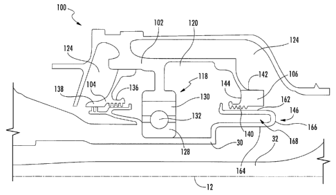
rolling elements supported within a paired race. To maintain a rotor critical
speed
margin, the rotor assembly is typically supported on three bearing assemblies:
one thrust
bearing assembly and two roller bearing assemblies. The thrust bearing
assembly
supports the rotor shaft and minimizes axial and radial movement thereof,
while the roller
bearing assemblies support radial movement of the rotor shaft.
[0004] Typically, these bearing assemblies are enclosed within a housing
disposed
radially around the bearing assembly. The housing forms a compartment or sump
that
holds a lubricant (e.g., oil) for lubricating the bearing. This lubricant may
also be
lubricant gears and other seals. Gaps between the housing and the rotor shaft
are
1
CA 02934088 2016-06-23
280683
necessary to permit rotation of the rotor shaft relative to the housing. The
bearing sealing
system usually includes two such gaps: one on the upstream end and another on
the
downstream end. In this respect, a seal disposed in each gap prevents the
lubricant from
escaping the compartment. Known seals include labyrinth or knife-edge seals
and carbon
seals.
[0005] However, the carbon seals may directly contact the moving rotor
shaft, which
may reduce the wear life of the seals and require dedicated cooling thereof.
In this
respect, many gas turbines now use hydrodynamic seals, which do not contact
the
rotating rotor shaft at high speed. Specifically, hydrodynamic carbon seals
draw air
through the seal and into the compartment, thereby maintaining a gap between
the
moving components and the stationary components. The pressure of air drawn
into the
compartment prevents the lubricant from escaping. Nevertheless, the use of two
hydrodynamic seals instead of contact seals increases the size, weight, cost,
and
installation complexity of the bearing compartment sealing system.
[0006] Accordingly, a bearing compartment sealing system for a gas turbine
engine
that can provide improved wear life, reduce the volume of air drawn into the
compartment during operation, and eliminate the need for dedicated seal
cooling would
be welcomed in the technology.
BRIEF DESCRIPTION OF THE INVENTION
[0007] Aspects and advantages of the invention will be set forth in part in
the
following description, or may be obvious from the description, or may be
learned through
practice of the invention.
[0008] In one aspect, the present disclosure is directed to a bearing
compartment
sealing system including a bearing for supporting a shaft. A housing encloses
the bearing
and defines a compartment for holding lubricant therein. At least two seals
are located
between the shaft and the housing. The at least two seals, the housing, and
the shaft
2
CA 02934088 2016-06-23
280683
collectively enclose the compartment. Only one of the at least two seals is a
hydrodynamic seal.
[0009] Another aspect of the present disclosure is directed to a gas
turbine engine.
The gas turbine engine includes a compressor, a combustor, a turbine, and a
shaft
rotatably coupling the compressor and the turbine. A bearing is positioned
between the
shaft and one of the compressor or the turbine. A housing encloses the bearing
and
defines a compartment for holding lubricant therein. At least one pump for
recirculating
lubricant between the compartment and a remote lubricant reservoir. At least
two seals
are located between the shaft and the housing. The at least two seals, the
housing, and
the shaft collectively enclose the compartment. Only one of the at least two
seals is a
hydrodynamic seal.
[0010] A further aspect of the present disclosure includes a method for
sealing a
bearing compartment in a gas turbine engine. The method includes at least
partially
supporting a shaft having a longitudinal axis with at least one bearing. The
shaft is rotated
about the longitudinal axis. Each of the at least one bearing is at least
partially enclosed
with a housing that defines a compartment for holding lubricant for
lubricating the at
least one bearing. A first pressure is created on an outer side of a
hydrodynamic seal and
an outer side of a labyrinth seal. A second pressure is created on an inner
side of the
hydrodynamic seal and an inner side of the labyrinth seal. The first pressure
is relatively
greater than the second pressure, thereby drawing air through the hydrodynamic
seal into
the compartment.
[0011] These and other features, aspects and advantages of the present
invention will
be better understood with reference to the following description and appended
claims.
The accompanying drawings, which are incorporated in and constitute a part of
this
specification, illustrate embodiments of the invention and, together with the
description,
serve to explain the principles of the invention.
3
CA 02934088 2016-06-23
280683
BRIEF DESCRIPTION OF THE DRAWINGS
[0012] A full and enabling disclosure of the present invention, including
the best
mode thereof, directed to one of ordinary skill in the art, is set forth in
the specification,
which makes reference to the appended figures, in which:
[0013] FIG. 1 is a cross-sectional view of one embodiment of a gas turbine
engine
that may be utilized within an aircraft in accordance with aspects of the
present subject
matter;
[0014] FIG. 2 is a cross-sectional view of one embodiment of a bearing
compartment
sealing system for sealing a bearing compartment housing relative to a shaft
of the gas
turbine engine in accordance with aspects of the present subject matter;
[0015] FIG. 3 is a close-up cross-sectional view of the bearing compartment
sealing
system shown in FIG. 2, particularly illustrating a labyrinth seal and a
hydrodynamic
carbon seal disposed axially opposite ends of the bearing compartment housing;
[0016] FIG. 4 is a schematic view of a lubricant circulation system for de-
aerating
lubricant in the gas turbine, and more specifically in the compartment, in
accordance with
aspects of the present subject matter; and
[0017] FIG. 5 is a flow chart of a method of using the bearing compartment
sealing
system in accordance with aspects of the present subject matter.
DETAILED DESCRIPTION OF THE INVENTION
[0018] Reference now will be made in detail to embodiments of the
invention, one or
more examples of which are illustrated in the drawings. Each example is
provided by
way of explanation of the invention, not limitation of the invention. In fact,
it will be
apparent to those skilled in the art that various modifications and variations
can be made
in the present invention without departing from the scope of the invention.
For instance,
features illustrated or described as part of one embodiment can be used with
another
4
CA 02934088 2016-06-23
280683
embodiment to yield a still further embodiment. Thus, it is intended that the
present
invention covers such modifications and variations as come within the scope of
the
appended claims and their equivalents.
[0019] An improved bearing compartment sealing system is generally provided
for a
gas turbine engine. Specifically, in several embodiments, the sealing system
may include
a housing that at least partially encloses a bearing supporting a shaft. The
housing
defines a compartment for holding lubricant for lubricating the bearing. The
sealing
system further includes a hydrodynamic carbon seal and a labyrinth seal for
sealing
between the housing and the shaft. The outer surfaces of the hydrodynamic and
labyrinth
seals experience a first pressure. The inner surfaces of the hydrodynamic and
labyrinth
seals experience a second pressure. The first pressure is relatively greater
than the
second, thereby preventing the lubricant from escaping the compartment.
[0020] Additionally, as will be described below, the sealing system may
include a de-
aerating system for de-aerating and recirculating the lubricant in the
compartment. For
example, a scavenge pump may pump lubricant from the compartment through to a
lubricant cooler to a lubricant reservoir. A de-aerator may remove air
entrained in the
lubricant. A fresh lubricant pump may then pump fresh lubricant from the
lubricant
reservoir to the compartment to further bearing lubrication.
[0021] Referring now to the drawings, FIG. 1 illustrates a cross-sectional
view of one
embodiment of a gas turbine engine 10 that may be utilized within an aircraft
in
accordance with aspects of the present subject matter, with the .engine 10
being shown
having a longitudinal or axial centerline axis 12 extending therethrough for
reference
purposes. In general, the engine 10 may include a core gas turbine engine
(indicated
generally by reference character 14) and a fan section 16 positioned upstream
thereof.
The core engine 14 may generally include a substantially tubular outer casing
18 that
defines an annular inlet 20. In addition, the outer casing 18 may further
enclose and
support a booster compressor 22 for increasing the pressure of the air that
enters the core
engine 14 to a first pressure level. A high pressure, multi-stage, axial-flow
compressor
CA 02934088 2016-06-23
280683
24 may then receive the pressurized air from the booster compressor 22 and
further
increase the pressure of such air. The pressurized air exiting the high-
pressure
compressor 24 may then flow to a combustor 26 within which fuel is injected
into the
flow of pressurized air, with the resulting mixture being combusted within the
combustor
26. The high energy combustion products are directed from the combustor 26
along the
hot gas path of the engine 10 to a first (high pressure) turbine 28 for
driving the high
pressure compressor 24 via a first (high pressure) drive shaft 30, and then to
a second
(low pressure) turbine 32 for driving the booster compressor 22 and fan
section 16 via a
second (low pressure) drive shaft 34 generally coaxial with first drive shaft
30. After
driving each of turbines 28 and 32, the combustion products may be expelled
from the
core engine 14 via an exhaust nozzle 36 to provide propulsive jet thrust.
[0022] Additionally, as shown in FIG. 1, the fan section 16 of the engine
10 may
generally include a rotatable, axial-flow fan rotor assembly 38 surrounded by
an annular
fan casing 40. It should be appreciated by those of ordinary skill in the art
that the fan
casing 40 may be supported relative to the core engine 14 by a plurality of
substantially
radially-extending, circumferentially-spaced outlet guide vanes 42. As such,
the fan
casing 40 may enclose the fan rotor assembly 38 and its corresponding fan
rotor blades
44. Moreover, a downstream section 46 of the fan casing 40 may extend over an
outer
portion of the core engine 14 so as to define a secondary, or by-pass, airflow
conduit 48
providing additional propulsive jet thrust.
[0023] It should be appreciated that, in several embodiments, the second
(low
pressure) drive shaft 34 may be directly coupled to the fan rotor assembly 38
to provide a
direct-drive configuration. Alternatively, the second drive shaft 34 may be
coupled to the
fan rotor assembly 38 via a speed reduction device 37 (e.g., a reduction gear
or gearbox)
to provide an indirect-drive or geared drive configuration. Such a speed
reduction
device(s) may also be provided between any other suitable shafts *and/or
spools within the
engine as desired or required.
6
CA 02934088 2016-06-23
280683
[0024] During operation of the engine 10, it should be appreciated that an
initial air
flow (indicated by arrow 50) may enter the engine 10 through an associated
inlet 52 of
the fan casing 40. The air flow 50 then passes through the fan blades 44 and
splits into a
first compressed air flow (indicated by arrow 54) that moves through conduit
48 and a
second compressed air flow (indicated by arrow 56) which enters- the booster
compressor
22. The pressure of the second compressed air flow 56 is then increased and
enters the
high pressure compressor 24 (as indicated by arrow 58). After mixing with fuel
and being
combusted within the combustor 26, the combustion products 60 exit the
combustor
26 and flow through the first turbine 28. Thereafter, the combustion products
60 flow
through the second turbine 32 and exit the exhaust nozzle 36 to provide thrust
for the
engine 10.
[0025] Referring now to FIGS. 2-4, various views of one embodiment of a
bearing
compartment sealing system 100 suitable for use within the gas turbine engine
10 are
illustrated in accordance with aspects of the present subject matter.
Specifically, FIG. 2
is a cross-sectional view of the sealing system 100 for sealing a bearing
compartment
housing 102 relative to a shaft of the gas turbine engine 10. FIG. 3 is a
close-up cross-
sectional view of the sealing system 100 shown in FIG. 2, particularly
illustrating a
labyrinth seal 104 and a hydrodynamic seal 106 disposed at axially opposite
ends of the
bearing compartment housing 102. Additionally, FIG. 4 is a schematic view of
an
optional lubricant de-aerating system 108 for de-aerating lubricant from the
compartment
102. Furthermore, FIG. 5 is a flow chart of a method 200 of using the sealing
system 100
to seal a compartment 120.
[0026] As shown in FIG. 2, the sealing system 100 may generally seal
between the
bearing compartment housing 102 and the high pressure drive shaft 30, which
rotates
relative thereto. Although, the sealing system 100 may seal between any
stationary
component and any rotating shaft (e.g., the low pressure drive shaft 34) in
the engine 10.
The aforementioned relative rotation occurs when one or more stator vanes 112
direct the
combustion products 60 flowing through a compressor conduit 114 onto one or
more
7
CA 02934088 2016-06-23
=
280683
turbine blades 116 coupled to the high pressure drive shaft 30. A bearing
assembly 118
supports the high pressure drive shaft 30 relative to various fixed components
in the
engine 10. The bearing compartment housing 102 at least partially radially
encloses the
bearing assembly 118, thereby forming a sump or compartment 120 preferably
having a
radial shape in which the bearing assembly 118 is disposed. Lubricant (e.g.,
oil) for
lubricating the various components of the bearing assembly 118 circulates
through the
compartment 120. A high pressure cavity 124 is disposed exterior to the
bearing
compartment housing 102. Preferably, bleed air from the turbine 28 flows
through a
bleed air port 126 to pressurize the high pressure cavity 124 to a pressure
relatively
greater than the pressure in the compartment 120.
[0027] At least two seals, such as the labyrinth seal 104 and the
hydrodynamic seal
106, between the high pressure drive shaft 30 and the bearing compartment
housing 102.
Although, the at least two seals may be any suitable type of seal as long as
one and only
one of the seals is the hydrodynamic seal 106. That is, there can be at most
one
hydrodynamic seal 106 in the sealing system 100. The labyrinth seal 104 and
the
hydrodynamic seal 106 separate the high pressure cavity 124 and the
compartment 120.
FIG. 2 illustrates the labyrinth seal 104 disposed upstream of the
hydrodynamic seal 106;
although, the hydrodynamic seal 106 may be positioned downstream of the
labyrinth seal
104 as well.
[0028] In this respect, the bearing compartment housing 102, the at least
two seals
(e.g., the labyrinth seal 104 and the hydrodynamic seal 106), and the high
pressure drive
shaft 30 collectively enclose the compartment 120. That is, the combination
the bearing
compartment housing 102, the at least two seals, and the high pressure drive
shaft 30
entirely surrounds the compartment 120 axially, radially, and
circumferentially.
Furthermore, the at least two seals (e.g., the labyrinth seal 104 and the
hydrodynamic seal
106) are the only seals that enclose the compartment 120.
[0029] In the embodiment illustrated in FIG. 3, the bearing assembly 118
may be a
roller bearing. Although, the bearing assembly 118 may be a thrust bearing or
any other
8
CA 02934088 2016-06-23
280683
type of bearing known in the art. More specifically, the bearing assembly 118
includes
an inner race 128 extending circumferentially around the outer surface of the
high
pressure drive shaft 30. An outer race 130 is disposed radially outward from
the inner
race 128 and mates with the interior surface of the bearing compartment
housing 102.
The inner and outer races 128, 130 may have a split race configuration. The
inner and
outer race 128, 130 sandwich at least one rolling element 132 therebetween.
Preferably,
the inner and outer races 128, 130 sandwich at least three rolling elements
132
therebetween. The rolling elements 132 may generally correspond to any
suitable
bearing elements, such as balls or rollers.
[0030] FIG. 3 also more closely illustrates the labyrinth seal 104 and the
hydrodynamic seal 106. Importantly, the labyrinth seal 104 and the
hydrodynamic seal
106 are non-contact seals, which require no contact between the stationary and
moving
components when operating at high speed. Non-contact seals typically have a
longer
service life than contact seals. But, each type of seal operates in a
different manner. The
labyrinth seal 104 includes inner surface 136 and an outer surface 138. A
tortuous path
(not shown) extending between the inner and outer surfaces 136, 138 prevents
lubricant
from escaping the compartment 102. The air pressure on an outer side 138 of
the
labyrinth seal 104 (i.e., in the high pressure cavity 124) is greater than the
air pressure on
the inner side 136 of the labyrinth seal 104 (i.e., in the compartment 120).
In this respect,
the stationary and rotating components are separated by an air film during
relative
rotation therebetween.
[0031] Nevertheless, the hydrodynamic seal 106 includes one or more grooves
140
separating the stationary and rotating components. The air pressure on an
outer side 142
of the hydrodynamic seal 106 (i.e., in the high pressure cavity 124) is
greater than the air
pressure on the inner side 144 of the hydrodynamic seal 106 (i.e., in the
compartment
120). As such, air from the high pressure cavity 124 flows through the grooves
140 into
the compartment 120, thereby creating an air film between the stationary and
rotating
components.
9
CA 02934088 2016-06-23
280683
[0032] In one embodiment, the hydrodynamic seal 106 is proximate to and in
sealing
engagement with a hairpin member 146 of the high pressure drive shaft 30. More
specifically, the hairpin member 146 includes a radially outer shaft portion
162 radially
offset from a radially inner shaft portion 164 by a radial wall 166. In this
respect, the
radially outer shaft portion 162, the radially inner shaft portion 164, and
the radial wall
166 define a cavity 168 therebetween. In one embodiment, the radially outer
shaft
portion 162 is in sealing engagement with the hydrodynamic seal 106. In this
respect, the
radially outer shaft portion 162 contacts the hydrodynamic seal 106 when the
high
pressure drive shaft 30 is stationary or rotating at low speeds. Nevertheless,
the
hydrodynamic seal 106 lifts off of the radially outer shaft portion 162 when
the high
pressure drive shaft 30 rotates at high speeds.
[0033] The hairpin member 146 may also improve the performance of the gas
turbine
engine 10. More specifically, lubricant from the compartment 120 is able to
contact and
cool the radially inner side of the radially outer shaft portion 162 of the
hairpin member
146. This, in turn, cools the radially outer side of the radially outer shaft
portion 162,
which is in contact with the hydrodynamic seal 106 at low speeds and proximate
to the
hydrodynamic seal 106 at high speeds. That is, heat from the radially outer
side conducts
through the radially outer shaft portion 162 to the radially inner side
thereof, which is
cooled by lubricant. This keeps the hydrodynamic seal 106 cooler, which, in
turn,
permits the gas turbine engine 10 to run hotter and faster, thereby improving
the
performance thereof.
[0034] Importantly, the pressure on the outer side 138 of the labyrinth
seal 104 and
the outer side 142 of the hydrodynamic seal 106 should be substantially the
same. That
is, the air pressure in the high pressure cavity 124 should be substantially
the same
throughout to prevent the creation of air flow currents. These air currents
could direct air
away from the hydrodynamic seal 106.
[0035] FIG. 4 is a schematic view of one embodiment of the optional
lubricant
circulation system 108. As mentioned above, the air flows through the
labyrinth seal 104
CA 02934088 2016-06-23
280683
and the hydrodynamic seal 106 into the compartment 120. As such, this air and
the heat
associated therewith should be removed to maintain proper lubricant
properties. In this
respect, the de-aerating system 108 may include a scavenge pump 148 that pumps
air-
entrained lubricant from compartment 120 to a lubricant reservoir 150. Before
reaching
the reservoir 150, the lubricant may optionally pass through a scavenge filter
152 to
remove any impurities or contaminants therein. A lubricant cooler 154 may cool
the
lubricant, which may have been heated from hot bleed air from the turbine 28
or friction
from the bearing assembly 118. A de-aerator 156 removes air entrained in the
lubricant
prior to storage in the reservoir 150. A fresh lubricant pump 158 may pump
lubricant
from the lubricant reservoir 150 to the compartment 120 as needed to replace
lubricant
pumped from the compartment 120 by the scavenge pump 148. The lubricant may
optionally pass through a supply filter 160 before entering the compartment
120.
[0036] FIG. 5 is a
flow chart illustrating an exemplary method for sealing a bearing
compartment housing and an associated shaft. In step (202), a shaft, such as
the high
pressure drive shaft 30, is at least partially supported by one or more
bearing assemblies
118. Each of the one or more bearing assemblies 118 is at least partially
enclosed by the
bearing compartment housing 102 in step (204). Next, in step (206), the high
pressure
drive shaft 30 is rotated about the longitudinal axis 12. As discussed in
greater detail
above, the high pressure drive shaft 30 generally rotates when the combustion
products
60 flow through the turbine 28. A first pressure is created on the outer side
138 of the
labyrinth seal 104 and the outer side 142 of the hydrodynamic seal 106 (i.e.,
in the high
pressure cavity 124) in step (208). In one embodiment, this first pressure may
be
supplied by bleed air from the turbine 28. Then, in step (210), a second
pressure is
created on the inner side 136 of the labyrinth seal 104 and the inner side 144
of the
hydrodynamic seal 106. The first pressure is relatively greater than the
second pressure.
As such, air flows from the high pressure cavity 124 to the compartment 120,
thereby
creating an air film between the stationary and rotating components. Steps
(208) and
(210) may be done in reverse order or simultaneously.
11
CA 02934088 2016-06-23
280683
[0037] The bearing compartment sealing system 100 is particularly
advantageous
over known sealing systems. Unlike many contact sealing arrangements, the
sealing
system 100 is a non-contact sealing arrangement. The reduced friction
associated with
non-contact sealing results in longer service life, lower maintenance and
repair costs, and
greater time on wing (TOW) than known contact sealing arrangements.
Furthermore, the
sealing system 100 requires no dedicated cooling unlike contact seals. The
sealing system
100, having one hydrodynamic seal and one labyrinth seal, draws less air into
the
compartment than sealing arrangements with two labyrinth seals. That is, air
flow is
greater through a labyrinth seal than a hydrodynamic seal. As such, less heat
is pulled
into the compartment 120, thereby reducing the load on the gas turbine engine
thermal
system and permitting a higher temperature limit in the compartment 120. The
sealing
system 100 is also lighter, less expensive, and smaller than sealing
arrangements with two
hydrodynamic seals.
[0038] While there have been described herein what are considered to be
preferred
and exemplary embodiments of the present invention, other modifications of
these
embodiments falling within the scope of the invention described herein shall
be apparent
=
to those skilled in the art.
12