Note: Descriptions are shown in the official language in which they were submitted.
CA 02934409 2016-06-27
TIMEPIECE COMPRISING A NEAR FIELD COMMUNICATION DEVICE
The invention concerns a timepiece provided with an automatic, mechanical or
electronic movement such as a quartz movement comprising a near field
communication device of NFC or RFID type, the communication device having an
electronic chip connected to an antenna.
It is known in the prior art how to equip a timepiece with a near field
communication
device in order to improve its tracking throughout the course of its lifetime
or to fight
against the piracy to which it might be subjected. In the course of its
operation, the
communication device is able to connect to an associated peripheral when it
finds itself
at a close distance from the latter and to send it a radio signal regarding
information
about it.
Generally speaking, in the prior art such a communication device is disposed
inside
components of the timepiece such as the casing, the caseband, the wristband,
or even
the glass.
However, one major drawback of such a communication device so arranged in the
timepiece is due to the fact that it often suffers from a lack of reliability.
In fact, the
particular arrangement of this communication device in components of the
timepiece
which are essentially metallic produces much electromagnetic perturbation.
Such
perturbation results from reflection and/or absorption of signals emitted by
the
communication device when it is in proximity to the peripheral. This
perturbation is
liable to cause malfunctions in the context of establishing a connection with
the
peripheral or maintaining this connection.
To mitigate this drawback, it is common in the prior art to use a
communication device
having an antenna of large size.
However, the integration of such an antenna in the timepiece and in particular
in its
components is a complex and tedious operation. What is more, such an
integration
makes difficult any subsequent intervention in the timepiece in order to
provide for its
upkeep and/or repair.
2
The present invention intends to mitigate such drawbacks connected to the
timepieces
of the prior art.
According to a general aspect of the disclosure, there is provided a timepiece
comprising: a bezel comprising a near field communication device able to
receive/send
a signal, wherein said communication device comprises a chip and an antenna
and is
arranged in a pocket of the bezel of said timepiece, the communication device
being
associated with a magnetic screen, and wherein the magnetic screen is located
on a
bottom wall and on at least two opposed lateral walls of the pocket.
In this design, the timepiece provided with a dial and/or a bezel comprising a
near field
communication device able to receive/send a signal, said communication device
comprising a chip and an antenna and being arranged in the area of the dial or
the bezel
of said timepiece and the communication device being associated with a
magnetic
screen, especially one made of ferrite.
In other embodiments:
- when the communication device is arranged in the area of the dial, the
dial has a
lower surface on which is arranged said communication device;
- when the communication device is arranged in the area of the dial, the
dial has a
lower surface provided with a pocket in which said communication device is
arranged;
- when the communication device is arranged in the area of the dial, the
dial has
an upper surface on which said communication device is arranged;
- when the communication device is arranged in the area of the dial, the
dial has
upper and lower surfaces between which said communication device is
arranged;
- when the communication device is arranged in the area of the bezel, the
bezel is
a monobloc piece comprising a lower surface having a pocket in which said
communication device is arranged;
- the magnetic screen of a signal is situated on a lower surface of the
dial so as to
close an opening formed by a pocket on the lower surface when the
communication device is arranged in the area of the dial or the magnetic
screen
Date Recue/Date Received 2023-03-20
2a
is situated on a lower surface of the bezel so as to close an opening formed
by
the pocket on the lower surface when the communication device is arranged in
the area of the bezel;
- the bezel comprises first and second components, the second
component
comprising a second interior surface provided with a pocket able to receive
said
communication device;
Date Recite/Date Received 2023-03-20
CA 02934409 2016-06-27
3
- the magnetic screen of a signal is situated on a bottom wall and/or a
lateral wall
of the pocket;
- the dial and/or the bezel are each made of a material having no
electrical
conductivity properties;
- the magnetic screen comprises at least one layer and/or one plate and/or
one film
and/or one metallic deposit, especially of ferrite;
- the communication device comprises a substrate made of plastic or
laminated
composites on which are glued an electronic chip and an antenna, and
- the communication device is of the NFC or RFID technology type.
Other advantages and characteristics of the invention will become more
apparent from a
reading of the following description of two preferred embodiments, making
reference to
the figures, shown for illustration and not for limitation:
- figure 1 is a schematic representation of a first variant of a dial of a
timepiece
comprising a communication device according to a first embodiment of the
invention;
- figure 2 is a schematic representation of a sectional view of the first
variant of
the dial according to the first embodiment of the invention;
- figure 3 is a view of an upper surface of the first variant of the dial
according to
the first embodiment of the invention;
- figure 4 is a sectional view AA of the first variant of the dial illustrated
in figure
3;
- figure 5 is a schematic representation of a sectional view of a second
variant of
the dial according to the first embodiment of the invention;
- figure 6 is a schematic representation of the second variant of the dial of
the
timepiece comprising a communication device according to a first embodiment of
the invention;
- figure 7 represents schematically a third variant of the dial according
to the first
embodiment of the invention;
- figure 8 represents schematically a fourth variant of the dial according to
the first
embodiment of the invention;
- figure 9 represents a sectional view of a case of the timepiece comprising a
first
variant of a bezel according to a second embodiment of the invention;
CA 02934409 2016-06-27
4
- figure 10 represents a sectional view of the case of the timepiece
comprising a
second variant of the bezel according to the second embodiment of the
invention;
- figure 11A is a schematic representation of a timepiece without a
magnetic
screen, and
- figure 11B is a schematic representation of the timepiece comprising the
magnetic screen according to the first and second embodiments of the
invention.
In the present invention, the timepiece 35 is provided with a case 20 having a
caseband
22 and a bottom 24, visible in figure 9. The case 20 of this timepiece 35 is
able to
receive an automatic, mechanical or even electronic movement such as a quartz
movement. This movement is topped by a dial 1 and a set of hands on top of
which is
placed a glass 21. This timepiece 35 likewise comprises a bezel 2 which can be
fixed or
rotary and which is preferably disposed in the area of the edge of the
caseband 22.
Figures 1 to 10 describe embodiments of the timepiece 35 comprising a near
field
communication device 4 able to send/receive a signal, as well as a magnetic
screen 8.
More precisely, in figures 1 to 8 a first embodiment of the timepiece 35
comprises the
communication device 4 arranged in the area of the dial. In a second
embodiment of this
timepiece 35, represented in figures 9 and 10, the communication device 4 is
located in
the area of the bezel 2 of the timepiece 35.
This communication device 4 implements, for example, wireless communication
technologies of short range and high frequency of the NFC type (Near Field
Communication) or RFID type (Radio Frequency Identification). This
communication
device 4 operates preferably in the high frequencies HF, for example at 13.56
MHz. But
in other variants, it can operate in the following frequency bands:
- low frequencies LF, for example between 125 kHz and 134.2 kHz;
- ultrahigh frequencies UHF, for example between 860 MHz and 960 MHz;
- superhigh frequencies SHF, for example at 2.45 GHz.
Such technologies thus allow the timepiece 35 to exchange information at short
distances with other associated peripherals. Such distances can lie between
around 0 and
20 cm, preferably between 0 and 2 cm. This communication device 4 can be the
passive
CA 02934409 2016-06-27
type with energy furnished to it by the radio frequencies emitted by each
associated
peripheral. In other words, this communication device 4 functioning in the
passive type,
uses an electric induction mechanism in the chip to be powered. Moreover, it
will be
notice that unlike to the Bluetooth technology, the communication device
allows
5 transfers of very limited data volumes and at very close range. These
transfers are
controlled and allow high security.
Such short distances between the timepiece 35 and each associated peripheral
make it
possible to avoid any involuntary activation of establishing a connection
between the
latter and likewise help limit all attempts at an unauthorized connection
which may
result from acts of piracy.
More precisely, this near field communication device 4 comprises an electronic
chip 6
and at least one antenna 5. The chip 6, which is connected to said at least
one antenna 5,
contains hardware and software elements. In this context, the hardware and/or
software
elements of the chip 6 of the device 4 comprise more precisely at least one
microprocessor 13a cooperating with memory elements 13b. This chip 6 may be
able to
execute program code instructions to implement a computer program. The memory
elements 13b of this chip 6 can save data regarding information about the
timepiece 35
or about the wearer of this timepiece. It will be noted that in one
alternative the
communication device 4 can contain a substrate 16 made of plastic or laminated
composites on which the chip 6 and the antenna 5 are glued.
In this timepiece 35, the magnetic screen 8 also known as a magnetic shielding
element
has a magnetic permeability adapted to the frequency bands of the magnetic
field
generated by the communication device 4. For example, when the communication
device 4 is operating in the high frequency HF band, the magnetic screen 8 has
a strong
initial magnetic permeability p' with f > 100 and low magnetic losses p" with
p." < 7,
and preferably a magnetic permeability p.' of 150 and magnetic losses p" of 5.
Such a magnetic screen 8 preferably has an electrical resistivity greater than
1000 KO/m
and a thickness between 50 and 200 p.m, and preferably 180 p.m.
The magnetic screen 8 can preferably be made of metallic material, such as
ferrite.
CA 02934409 2016-06-27
6
This magnetic screen 8 makes it possible to avoid a modification of the
magnetic field
sent or received by the communication device, which modification would be due
to the
presence of various metallic components 33 situated in the immediate
surroundings of
the communication device 4 such as the case 20 or even the movement of the
timepiece
35. In fact, the magnetic screen 8 tends to be able to lessen the negative
influence which
these metallic components 33 might have on the performance of the
communication
device 4. This negative influence might involve the attenuation of the
magnetic field
generated or received by this communication device 4.
More precisely, figure 9A illustrates a schematic representation of a
timepiece 31
comprising the communication device 4 arranged in the area of the bezel 1
and/or the
dial 2 and metallic components 33 such as the case 20 or also the movement.
This
timepiece 31 is different from that of the invention in that it lacks the
magnetic screen 8.
In this configuration, when the communication device 4 generates a magnetic
field
characterized by the lines of magnetic flux, these lines pass through the
zones of this or
these metallic components 33 situated in the immediate surroundings of the
communication device 4. The variations of this magnetic field passing through
these
metallic components 33 are liable to create the appearance of electric
currents known as
"Foucault currents" in these zones. The creation of such electric currents in
these zones
has the effect of attenuating the strength of this magnetic field.
In figure 9B, the timepiece 35 comprises, in addition to the communication
device 4 and
metallic components 33, the magnetic screen 8, as is the case in the present
embodiment
of the invention. This magnetic screen 8 is arranged between the communication
device
4 and the metallic component(s) 33 which are in the immediate surroundings of
this
device 4, according to different configurations described below. Under these
conditions,
when the communication device 4 generates a magnetic field, the latter does
not pass
through the zones of this or these metallic components 33 situated in the
immediate
surroundings of the communication device 4. In fact, the magnetic screen 8 is
able to
channel this magnetic field by modifying the lines of magnetic flux resulting
from this
field, so that these lines do not pass through the metallic components 33.
Thus, this or
these metallic components 33 are then magnetically isolated from the magnetic
field
generated by the communication device 4. In other words, the magnetic screen 8
is able
CA 02934409 2016-06-27
7
to separate the timepiece 35 into two zones, a first zone containing the
magnetic fields
generated by the communication device 4 and a second zone not exposed to these
magnetic fields thanks to the action of the magnetic screen 8.
Thus, this magnetic screen 8 makes it possible to improve the efficiency and
the
sensitivity of the reception/transmission of radio signals by the antenna 5 of
the
communication device 4 by isolating this antenna 5 from the metallic
components 33
comprised in its immediate surroundings.
It will be noted that this magnetic screen 8 can be flexible or rigid and can
contain at
least one layer, one plate, one film or one metallic deposit, preferably of
ferrite or also a
polymer resin ballasted with metallic particles of ferrite. Such a magnetic
screen 8 is
thus of small footprint.
In the timepiece 35, the magnetic screen 8 is associated with the
communication device
4 by being arranged in the timepiece 35 relative to this communication device
4, or
relative to this communication device 4 and at least one metallic component 33
of said
timepiece 35 comprised in the immediate surroundings of the communication
device 4.
In the different variants of the two embodiments described below, the magnetic
screen 8
is associated with the communication device 4 by being arranged relative to
the latter
such that there is a spacing of around 0 to 2500 1..tm defined between them
and/or that
this magnetic screen 8 is disposed between the communication device 4 and at
least one
electrical component 33 comprised in the immediate surroundings of said device
4.
It will be noted that when the spacing between the magnetic screen 8 and the
communication device 4 is basically zero, the magnetic screen 8 can then be
associated
with the communication device 4 by producing the magnetic screen with a
technique of
printing, silk screening, gluing or vapour deposition of a metallic paint onto
a support
contained or mounted in the communication device 4. One will then choose a
support
having excellent electrical insulation properties. This support can be a layer
of material,
a film, a band, etc. In this configuration, this support can be located solely
in the area of
the antenna 5 of the communication device 4 or also in the area of the antenna
5 and the
chip 6.
CA 02934409 2016-06-27
8
As an example, this magnetic screen 8 is associated with the communication
device 4
by being arranged in the timepiece 35 beneath this communication device 4,
that is,
between the movement constituting a metallic component 33 of said timepiece 35
and
this communication device 4. In this configuration, the magnetic screen 8 is
associated
with the communication device 4 by not being in direct contact with the
antenna 5 of
the communication device 4, but rather being able to be in contact with the
chip 6.
As we have mentioned above, in the first embodiment of the timepiece 35 the
communication device 4 is arranged in the area of the dial I. This first
embodiment
comprises four variants of dial 1 where the communication device 4 is
arranged. One
such dial 1 is of a monobloc design. It is made preferably of rigid material
able to
provide good strength, and a proper appearance of the display. What is more,
this
material has no electrical conductivity properties and it can be made for
example of
synthetic sapphire, ceramic, or also an injection moulded or cast polymer such
as
polyamide-nylon PA12, polycarbonate PC or polyphenylsulfone PPSu.
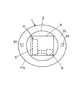
This dial 1 which is preferably of circular shape comprises an upper surface
Ila
constituting a visible display surface being opposite a lower surface II b
situated
opposite the movement of said timepiece 35.
The dial I likewise contains a peripheral wall 25 joining the lower and upper
surfaces
11b, ha to each other. It will be noted that the upper and lower surfaces ha,
lib can
be parallel to each other and that the intersections between the peripheral
wall 25 and
each of these surfaces 11a, 11 b define the peripheral edges 27a, 27b.
This dial 1 can comprise feet 34, which are used as a geometrical reference in
the
manufacturing process of the dial and also to secure this dial 1 to the case
20 and/or to
the movement. The case 20 and/or the movement then comprise orifices in which
these
feet 34 are engaged when the dial 1 is assembled with the case 20 and/or with
the
movement. Fixation elements such as screws engaging in threaded holes
transversely to
the orifices make it possible to ensure a mechanical connection between the
dial 1 and
the case 20 and/or the movement. These feet 34 can be arranged in the area of
the lower
surface 11 b of the dial (visible in figures 1, 2 and 4) and/or in the area of
the peripheral
wall 25 (visible in figures 5 and 6). Such feet 34 can correspond to lugs, for
example.
CA 02934409 2016-06-27
9
This upper surface 1 la can have, in the area of a peripheral zone, time
indicating
markings 7, such as hour and minute markings 7. These markings 7 can be
indexes or
digits (Roman or Arabic), or decorative elements such as small precious or
semiprecious stones, or a combination of two or three of the latter. The dial
I likewise
has an axial passage orifice 10 through which passes one free end of a shaft
connected
to a kinematic chain of the movement, able to carry the hands of the timepiece
35 above
the upper surface I la. The dial 1 also comprises an opening 9 through which
information pertaining to the date can be displayed.
In the first variant of the dial 1, illustrated in figures 1 to 4, the
communication device 4
is arranged on the lower surface 1 lb of the latter. More precisely, in this
variant the
lower surface 1lb comprises a pocket 3 in which the communication device 4 can
be
mounted. This pocket 3 is defined in this lower surface 11 b around the axial
passage
orifice 10 of the dial I. This pocket 3 has a wall 15a forming a bottom of the
pocket 3
hereinafter called the bottom wall 15a, and a lateral wall 15b, the lateral
wall 15b being
preferably perpendicular to the bottom wall 15a. The bottom wall 15a and the
lateral
wall 15b each have an essentially planar surface. The surface of the bottom
wall 15a is
comprised in a plane parallel to a portion 12 of the lower surface 1 lb not
forming this
pocket 3, or parallel to the upper surface 11 a.
The lateral wall 15b of this pocket 3 forms with the portion 12 of the lower
surface lib
an edge 26 which defines an opening of the pocket 3.
Referring to figure 3, this pocket 3 can have a general circular shape. In
fact, it can have
a zone forming a recess about the opening 9 made in the dial 1 for the display
of
information regarding the date.
In this variant, this pocket 3 is defined on around 40 to 90% of the lower
surface 11b,
and preferably on 80% of this surface. Moreover, this pocket 3 has a depth PI
of around
300 to 500 p.m, preferably 400
The communication device 4 comprising the chip 6 connected to at least one
antenna 5
is disposed in the pocket 3 formed in the dial 1. More precisely, the chip 6
and the
CA 02934409 2016-06-27
antenna 5 can be fixed to the bottom wall 15a by gluing or also by fitting
into fixation
elements present on this bottom wall 15a of the pocket 3. Alternatively, the
antenna 5
can be disposed on this bottom wall 15a by printing, silk screening, or vapour
deposition of a metallized paint.
5
In this variant of the dial 1, the alternative of the communication device 4
comprising
the substrate 16 made of plastic or laminated composites on which the chip 6
and the
antenna 5 are glued can likewise be arranged in this pocket 3, especially by
gluing.
10 In this variant of the dial 1, when the communication device 4 is
associated with the
magnetic screen 8, the opening of the dial 1 is wholly or partly closed by
this magnetic
screen 8. This magnetic screen 8 comprises a zone of fixation which is
mechanically
connected by gluing, fitting, or welding to the edge 26 of the opening of the
pocket 3,
namely, the portion 12 of the lower surface 1lb not constituting the pocket 3.
Alternatively, the magnetic screen 8 can have a shape essentially
complementary to that
of the opening so as to be able to be arranged there by fitting and thus cover
all or part
of this opening of the pocket 3. In this case, the magnetic screen 8 is
preferably rigid
and the edge 26 of the opening comprises a fitting zone able to cooperate with
the
contour of the magnetic screen 8.
Such an arrangement of the communication device 4 in this pocket 3 makes it
possible
to limit the footprint of this device 4 in the case 20 of the timepiece 35 so
as not to
disturb the functioning of the movement.
In the second variant of the dial 1 illustrated in figures 5 and 6, the
communication
device 4 comprising the chip 6 connected to at least one antenna 5 is disposed
in the
area of the lower surface llb of the dial 1. More precisely, the chip 6 and
the antenna 5
can be secured to the lower surface 1 lb by gluing or by fitting into fixation
elements
present on this lower surface 11 b. Alternatively, the antenna 5 can be
disposed on the
lower surface 11 b by printing, silk screening, or vapour deposition of a
metallized paint.
In this variant of the dial 1, the alternative of the communication device 4
comprising
the substrate 16 made of plastic or laminated composites on which the chip 6
and the
antenna 5 are glued can likewise be arranged on the lower surface 1 lb,
especially by
CA 02934409 2016-06-27
11
gluing.
In this variant, when the communication device 4 is associated with the
magnetic screen
8, the latter is then arranged on the lower surface 1 lb so as to cover the
communication
device 4. More precisely, this magnetic screen 8 can be arranged beneath the
antenna 5
or the antenna 5 and the chip 6 by being situated between the lower surface 11
b and the
movement. In this configuration, this magnetic screen 8 comprises at least one
layer,
one film or one metallic deposit which is able to cover the communication
device 4
arranged on the lower surface 11 b. Thus, the antenna 5 or the antenna 5 and
the chip 6
of the communication device 4 are comprised between the magnetic screen 8 and
the
lower surface 1 lb. This magnetic screen 8 can be applied to the lower surface
1lb so as
to cover the communication device 4 by the techniques of printing, silk
screening,
gluing, or vapour deposition of a metallic paint.
It will be noted that this second variant is particularly adapted to the dial
1 having feet
arranged on the peripheral wall 25 of the latter. In fact, in such a
configuration, the
communication device 4 and in particular the antenna can be arranged on a
larger
portion of the lower surface lib due to the absence of feet 34 of the dial 1
on the lower
surface 1 lb.
In the third variant of the dial I illustrated in figure 7, the communication
device 4 is
arranged on the upper surface lla of the dial 1. More precisely, in this
variant the
antenna 5 of this communication device 4 can be formed by at least one
metallic
element corresponding, for example, to a metallic wire, a layer, a film, or a
metallic
deposit. This element can be disposed on the upper surface I I a by the
different
alternatives, not exhaustive and nonlimiting, defined below.
In fact, in a first alternative illustrated in figure 7, the antenna 5 can be
a metallic
element having markings 7 present on this upper surface Ila which can be
connected to
each other by a component 14 of the metallic element. In this context, the
markings 7
and the component 14 are made of metallic material, such as copper or
aluminium.
In a second alternative, the antenna 5 can be a metallic element which is
arranged in the
area of the peripheral zone defined on the upper surface 1 la of the dial 1
where the
CA 02934409 2016-06-27
12
markings 7 are situated. In this case, the metallic element extends into this
peripheral
zone, making at least one turn around the dial 1 and hugging the markings 7.
In a third alternative, the metallic element can be arranged on the upper
surface I la in
the area of the peripheral edge 27a defined on this upper surface 11 a or,
optionally,
between the markings 7 and this edge 27a.
In these alternatives, the metallic element is preferably arranged on the
upper surface
Ila by overmoulding in the thickness of the dial 1 or by injection moulding so
that it is
not apparent. The metallic element can likewise be applied to the upper
surface 1 la by
the techniques of printing, silk screening, etching, gluing, or vapour
deposition of a
metallic paint, and in this case it will be visible on the upper surface lla
of this dial 1 so
as to constitute, for example, a motif having an aesthetic form.
It will be noted that when the markings 7 form with the component 14 an
antenna 5,
these markings 7 can then be made by the techniques mentioned above, such as
printing, silk screening, gluing, or vapour deposition of a metallic paint.
In this variant, the antenna 5 is then connected to the chip 6 of the
communication
device 4. This chip 6 is arranged on the upper surface 1 la of the dial 1 by
an
overmoulding or an injection moulding technique so as not to be apparent. The
chip 6
can likewise be applied to the upper surface 11a by a gluing technique and in
this case it
will be visible on the upper surface 11a of this dial I so as to constitute,
for example, a
motif having an aesthetic form.
In this variant of the dial 1, when the communication device 4 is associated
with the
magnetic screen 8, the latter is arranged on the lower surface 1lb of the dial
1. It can
likewise be arranged on the upper surface 11a, being situated beneath the
antenna 5 or
the antenna 5 and the chip 6. In this configuration, this magnetic screen 8
comprises at
least one layer, one film or one metallic deposit which is able to be applied
to one or the
other of the two surfaces 11a, 11 b of the dial I by the techniques of
printing, silk
screening, gluing, or vapour deposition of a metallic paint. Alternatively,
this magnetic
screen 8 can be arranged in the dial I by a technique of overmoulding or
injection
moulding, being comprised beneath the antenna 5 or the antenna 5 and the chip
6.
CA 02934409 2016-06-27
13
In a fourth variant of the dial I illustrated in figure 8, the communication
device 4 is
arranged in the dial 1 between the upper and lower surfaces 11a, II b. In this
configuration, the communication device 4 can have a substrate 16 made of
plastic or of
.. laminated composites on which the chip 6 and the antenna 5 are glued. The
communication device 4 is then mounted in the dial 1 by a technique of
overmoulding
or injection moulding.
In this variant of the dial 1, when the communication device 4 is associated
with the
magnetic screen 8, the latter is arranged on the lower surface lib of the dial
1. In this
configuration, this magnetic screen 8 comprises at least one layer, one film,
or one
metallic deposit and it can be applied to the lower surface 1 lb of the dial 1
by the
techniques of printing, silk screening, gluing, or vapour deposition of a
metallic paint.
Alternatively, this magnetic screen 8 can be arranged in the dial 1 beneath
the
communication device 4 by a technique of overmoulding or injection moulding.
Thus, as we have mentioned above, in the second embodiment of the timepiece 35
the
communication device 4 is arranged in the area of the bezel 2. This second
embodiment
defines two different variants of the bezel 2. In these two variants, the
bezel 2 is made
preferably of rigid material able to provide good strength and preferably
having no
electrical conductivity properties. This material may correspond, for example,
to
synthetic sapphire, ceramic, or also an injection moulded or cast polymer such
as
polyamide-nylon PA12, polycarbonate PC or polyphenylsulfone PPSu. This bezel 2
can
be circular in shape and comprise a lower surface 23b as well as an upper
surface 23a.
This upper surface 23a can constitute a visible display surface containing
time indicator
markings.
In the first variant of the bezel 2 illustrated in figure 9, the communication
device 4 is
arranged in the bezel 2. More precisely, in this variant, the bezel 2 is a
monobloc piece
whose lower surface 23b contains a pocket 18 in which the communication device
4 can
be positioned. This pocket 18 forms a throat or an annular groove extending
into the
lower surface 23b of the bezel 2. This pocket 18 has a transverse section
which can have
the shape of a U. Such a pocket 18 has a bottom wall 19a and a lateral wall
19b, the
lateral wall 19b being preferably perpendicular to the bottom wall 19a. The
bottom wall
CA 02934409 2016-06-27
14
19a and the lateral wall 19b each have an essentially planar surface.
The lateral wall 19b of this pocket 18 forms, with a portion 29 of the lower
surface 23b
not constituting this pocket 18, an edge 28 which defines an opening of the
pocket 18.
In this variant, the opening of this pocket 18 is defined on around 30 to 70%
of the
lower surface 23b, and preferably 50% of this surface 23b. This pocket 18 has
a depth
P2 of around 200 to 2500 um, preferably 1000
The communication device 4 comprising the chip 6 connected to at least one
antenna 5
is disposed in the pocket 18 formed in the bezel 2. More precisely, the chip 6
and the
antenna 5 can be secured to the bottom wall 19a and/or the lateral wall 19b by
gluing or
by fitting into fixation elements present on the bottom wall 19a and/or the
lateral wall
19b of the pocket 18. Alternatively, the antenna 5 can be disposed on the
bottom wall
19a and/or the lateral wall 19b by printing, silk screening, or vapour
deposition of a
metallized paint.
In this variant of the bezel 2, the alternative of the communication device 4
comprising
the substrate 16 made of plastic or laminated composites on which the chip 6
and the
antenna 5 are glued can likewise be arranged in this pocket 18, especially by
gluing or
by fitting, or by being driven in by mechanical resistance through dimensional
adjustment.
In this variant of the bezel 2, when the communication device 4 is associated
with the
magnetic screen 8, the opening of the pocket 18 is wholly or partly covered by
the
magnetic screen 8 so as to optimize the performance of the communication
device 4.
This magnetic screen 8 has a zone of fixation which is mechanically connected
by
gluing, by fitting, or by welding to the edge 28 of the opening of the pocket
18, namely,
to the portion 29 of the lower surface 23b. Alternatively, the magnetic screen
8 can have
a shape essentially complementary to that of the opening so that it can be
arranged
therein by fitting or gluing and thus cover all or part of this opening of the
pocket 18. In
this case, the magnetic screen 8 is preferably rigid and the edge 28 of the
opening has a
fitting zone able to cooperate with the contour of the magnetic screen 8.
CA 02934409 2016-06-27
In a second variant of the bezel 2 illustrated in figure 10, the communication
device 4 is
arranged in the bezel 2. More precisely, in this variant, the bezel 2 has a
first component
17a and a second component 17b. The first component 17a comprises the upper
surface
23a of the bezel 2 and a first interior surface 30a, and the second component
17b
5 contains the lower surface 23b of the bezel 2 and a second interior
surface 30b. When
the first component 17a is assembled with the second component 17b to form
this
variant of bezel 2, the first and second interior surfaces 30a, 30b are
arranged opposite
each other, being in contact for all or some of their surface. These first and
second
interior surfaces 30a, 30b have connection elements. The connection elements
of each
10 of these first and second surfaces 30a, 30b can have complementary
shapes in order to
ensure a mechanical connection between these two components 17a, 17b when they
are
assembled with each other.
In this variant, the second interior surface 30b of the second component 17b
has a
15 pocket 18 in which the communication device 4 can be arranged. This
pocket 18 forms
a throat or an annular groove extending into the second interior surface 30b
of the
second component 17b of the bezel 2. This pocket 18 has a transverse section
which can
have the shape of a U. Such a pocket 18 has a bottom wall 19a and a lateral
wall 19b,
each having an essentially planar surface, the lateral wall 19b being
preferably
perpendicular to the bottom wall 19a.
The lateral wall 19b of this pocket 18 forms, with a portion 29 of the second
interior
surface 30b not constituting this pocket 18, an edge 28 which defines an
opening of the
pocket 18.
In this variant, the opening of this pocket 18 is defined on around 30 to 70%
of the
second interior surface 30b, and preferably 50% of this surface. This pocket
18 has a
depth P3 of around 200 to 2500 lAm, preferably 1000
In this variant, when the communication device 4 is associated with the
magnetic screen
8, the latter is arranged in the pocket 18. This magnetic screen 8 can
correspond to a
layer, a film or a metallic deposit which is applied to the bottom wall 19a
and/or the
lateral wall 19b of the pocket 18. The application of this magnetic screen 8
in the pocket
18 can be done by a technique of printing, silk screening, or vapour
deposition of a
CA 02934409 2016-06-27
16
metallized paint.
The communication device 4 is then disposed in the pocket 18 above the
magnetic
screen 8. More precisely, the chip 6 and the antenna 5 can be fixed to at
least one
support element comprised on the bottom wall 19a and/or the lateral wall 19b
by gluing
or by fitting so that the antenna 5 of the communication device 4 is not in
contact with
the magnetic screen 8. The support element can correspond to at least one
fixation arm
or to a layer of material. This layer of material can cover all or part of the
magnetic
screen 8 arranged in the pocket 18, and have electrical insulating properties.
Alternatively, the communication device 4 can be fixed in a connection zone
defined on
the first interior surface 30a of the first component 17a. This connection
zone is situated
opposite the pocket 18 when the first and second components 17a, 17b are
assembled
with each other.
In this variant of the bezel 2, the alternative of the communication device 4
comprising
the substrate 16 made of plastic or laminated composites on which the chip and
the
antenna 5 are glued can likewise be arranged in this pocket 18, especially by
the same
principles mentioned above for this second variant.
In this second variant, the opening of this pocket 18 is then closed when the
first
component 17a is assembled with the second component 17b to form the bezel 2.
In these two embodiments of the invention, the communication device 4 and the
magnetic screen 8 can be comprised in a module for example by being
overmoulded in
the same piece of polymer. Such a module can then be arranged in the dial 1
and the
bezel 2 according to the different variants described above. The arrangement
of this
module in these different variants is preferably done so that the antenna 5
radiates
optimally in the direction of the associated peripheral with which the
timepiece 35 is
able to exchange data.
In this timepiece 35, the case 20 is adapted to optimize/maximize the
performance of
the communication device 4 arranged in the area of the bezel 2 or the dial 1.
In fact, this
case 20 can be made in whole or in part of a material having no electrical
conductivity
properties, such as synthetic sapphire, ceramic, or also an injection moulded
or cast
CA 02934409 2016-06-27
17
polymer such as polyamide-nylon PA12, polycarbonate PC or polyphenylsulfone
PPSu.
Thus, the case 20 can be made wholly of this material. But alternatively the
case 20 can
be made only partly of this material, having only some of these components
designed in
this material, such as the components which are situated on top of the dial 1,
such as a
portion of the caseband situated above the level of the dial 1 and the bezel
2.
Thus, as we have mentioned above, the dial 1, the bezel 2, or even all or some
of the
case 20 can be made of a material having no electrical conductivity
properties. The
electrical nonconductivity of such a material is quantified by its
resistivity, which
characterizes its capacity to resist the flow of electric current. The
resistivity of this
material is greater than 10121-2/cm, and preferably greater than 1013 C2/cm.
It will be noted that the arrangement of the communication device in upper
portions of
the timepiece such as the dial 1 and the bezel 2 makes it possible to limit
the
perturbation effects which may result from the wristband of the wearer of said
timepiece
35.
The present invention is not limited to the embodiments which have been
explicitly
described, but also includes the different variants and generalizations
contained in the
realm of the following claims.