Note: Descriptions are shown in the official language in which they were submitted.
CA 02934661 2016-06-20
WO 2015/095363
PCT/US2014/070912
IN STERILIZING CATHETERS AND CATHETER CONNECTORS
The present disclosure relates generally to catheters, and more particularly
to
catheters and catheter connectors including UV light for sterilization. The
disclosure has
particular utility in connection with sterilizing bacteria and other microbes
which may be
introduced to a patient through catheters and catheter connectors, as well as
through a
fluid flowing through catheters and/or catheter connectors, and will be
described in
connection with such utility, although other utilities are contemplated.
Many studies have shown that nosocomial (hospital-acquired) infections are a
leading cause of death in the United States. One source of such infections
involves the
entry of bacteria into intraluminal access sites.
As explained in the background section of U.S. Patent No. 7,834,328 to Redmond
et al. ("Redmond"), one of the first interventions that occurs when a patient
is admitted
into a hospital is the placement of an intravenous access line (IV). This
percutaneously-
placed IV line gives the caregivers a direct path to the patient's bloodstream
via a
peripheral vein for rapid administration of fluids, medication or for drawing
blood
samples. In more serious cases, where direct access to a high blood flow
supply is
needed, for example, in chemotherapy delivery, temporary kidney dialysis or
heart
monitoring catheterization, a Central Venous Access Catheter (CVAC or Central
Line) is
inserted. This line is typically inserted percutaneously into a major
branching vessel,
frequently the subclavian vein, and then the distal segment of the catheter is
directed into
the superior vena cava.
Both peripheral and central catheterization procedures create an open pathway
or
lumen from an external access site into the bloodstream. This intraluminal
access site
provides an attachment point for various therapeutic or diagnostic medical
devices,
including, but not limited to, stopcocks, needle-less access sites, IV bags,
infusion
pumps, drug delivery pumps, kidney dialysis equipment, thermal dilution
catheters, and
the like. Unfortunately, this access site also provides an entry point for
bacterial
infections. Therefore, each time the access site is opened to accommodate the
attachment
of a medical device there is an opportunity for bacteria to enter the catheter
lumen and be
transferred into the bloodstream.
In addition to the contamination of the catheter lumen via the external access
site,
bacteria can also enter by the skin puncture and sub-cutaneous tract that is
created by the
catheter when the IV or CVAC is placed. Bacteria can then find their way down
the
1
CA 02934661 2016-06-20
WO 2015/095363
PCT/US2014/070912
outside wall of the catheter to its distal end, infecting the tract along the
catheter wall as
they migrate.
In an attempt to mitigate the serious problems identified in the preceding
paragraphs, many prior art IV lines and CVACs use some type of molded plastic
fitting
at their proximal end terminated with a female Luer-lock or Luer-slip
connector. These
connectors must be closed by a Luer cap when not in use to prevent access site
contamination. Each time the line is to be accessed, the Luer cap must be
removed and
discarded as it must be assumed that the outside of the Luer cap is
contaminated and that
once removed it is nearly impossible to prevent the male Luer configuration
from
touching a contaminated surface. Therefore, standard prior art infection
control practice
is to always replace the Luer cap whenever the line is accessed. This
procedure is not
only costly, but the removal and replacement process provides additional
chances for
bacteria to enter the lumen of the connector.
Redmond, as well as other prior techniques, is thus primarily concerned with
bacterial infections that are caused by bacteria introduced into, and residing
within, a
Luer cap or other closure cap. To this end, Redmond discloses a substantially
UV-C
transparent closure cap for closing the access site, and an irradiating
apparatus which fits
over the transparent closure cap for irradiating the closure cap with UV-C
radiation,
thereby sterilizing the closure cap.
However, a drawback of the Redmond apparatus is that it requires the line to
be
capped, and thus cannot be sterilized while carrying a fluid to or from a
patient. Further,
some bacterial infections may be caused by bacteria that are not introduced
via the
closure cap, but rather from some point upstream of the access site. Moreover,
bacteria
may be introduced into a patient's body (whether into the blood stream, lungs,
bladder or
the like) through the fluid passing through the interior of a catheter.
See also US Patent 8,197,087, PCT Application Serial No. PCT/US2014/033207,
and US Published Application US 2012/0053512.
Thus, a heretofore unaddressed need exists in the industry to address the
aforementioned deficiencies and inadequacies.
Accordingly, a primary object of this disclosure is to provide catheters and
catheter connectors that may be utilized to provide UV sterilization of a
fluid as it flows
through the catheter and/or catheter connector. The present disclosure
provides catheters
and catheter connectors which not only sterilize bacteria and other microbes
which may
have been introduced through contamination of the connectors (e.g., as
catheters are
2
CA 02934661 2016-06-20
WO 2015/095363
PCT/US2014/070912
connected/disconnected), but also sterilize the fluid flowing within. Further,
sterilization
may be performed while the fluid flow, thus eliminating the need to cap a
catheter line in
order to provide sterilization.
In one aspect, the present disclosure provides a catheter connector that
includes
an inner wall and an outer wall. The inner wall defines an interior of the
catheter
connector and is transmissive to ultraviolet (UV) light. The outer wall
defines an
exterior of the catheter connector. The catheter connector further includes
one or a
plurality of UV light sources such as UV light-emitting diodes (LEDs) disposed
between
the inner wall and the outer wall and positioned to emit UV light into the
interior of the
catheter connector. Alternatively, one or a plurality of UV light-emitting
diodes may be
dispersed on the outer wall and positioned to emit UV light into the interior
of the
catheter connector. There may also be a reflective lining inserted between the
inner and
the outer wall to intensify the UV light beam. A flow sensor senses a flow of
fluid in the
interior of the catheter connector, and circuitry electrically connects the
plurality of UV
light sources, the flow sensor and a power source, such that electrical power
is supplied
to the UV light sources when a fluid flows through the interior of the
catheter connector.
In another aspect, the light may be turned on without requiring a sensor,
e.g., by manual
operation.
In another aspect, the present disclosure provides a catheter having a UV
light
sterilization portion. The UV light sterilization portion includes an inner
wall that defines
an interior of the catheter and is transmissive to ultraviolet (UV) light. An
outer wall
defines an exterior of the catheter. One or a plurality of UV light sources
such as UV
light-emitting diodes (LEDs) is disposed between the inner wall and the outer
wall and is
positioned to emit UV light into the interior of the catheter. Alternatively,
one or a
plurality of UV light sources such as UV light-emitting diodes may be disposed
on the
outer wall and positioned to emit UV light into the interior of the catheter.
A flow sensor
is provided for sensing a flow of fluid in the interior of the catheter, and
circuitry
electrically connects the plurality of UV light sources, the flow sensor and a
power
source, such that electrical power is supplied to the UV light sources when a
fluid flows
through the interior of the catheter.
In yet another aspect, the present disclosure provides a catheter connector
that
includes an inner wall defining an interior of the catheter connector and is
transmissive
to ultraviolet (UV) light. An outer wall defines an exterior of the catheter
connector. A
flow sensor senses a flow of fluid in the interior of the catheter connector.
One or more
3
CA 02934661 2016-06-20
WO 2015/095363
PCT/US2014/070912
optical fibers are included for transmitting UV light from a UV light source
into the
interior of the catheter connector. And, circuitry electrically connects the
UV light
source, the flow sensor and a power source, such that electrical power is
supplied to the
UV light source when a fluid flows through the interior of the catheter
connector.
The features, functions, and advantages that have been discussed can be
achieved
independently in various embodiments of the present disclosure or may be
combined in
yet other embodiments further details of which can be seen with reference to
the
following description and drawings.
Other features, functions and advantages of the present disclosure will be or
become apparent to one with skill in the art upon examination of the following
drawings
and detailed description. It is intended that all such additional systems,
methods,
features, and advantages be included within this description, be within the
scope of the
present disclosure, and be protected by the accompanying claims.
Many aspects of the disclosure can be better understood with reference to the
following drawings. The components in the drawings are not necessarily to
scale,
emphasis instead being placed upon clearly illustrating the principles of the
present
disclosure. Moreover, in the drawings, like reference numerals designate
corresponding
parts throughout the several views.
FIG. 1A is side elevation view, and FIG. 1B across sectional view of a
catheter
connector, in accordance with a first exemplary embodiment of the disclosure;
FIG. 2 is an illustration of a catheter connector, in accordance with a second
exemplary embodiment of the disclosure; and
FIG. 3 is an illustration of a catheter connector, in accordance with another
exemplary embodiment of the disclosure.
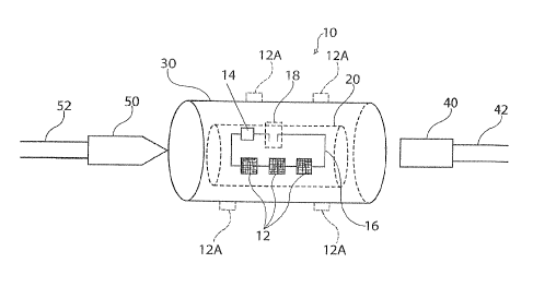
FIG. IA and FIG. 1B are illustrations of a catheter connector 10 (hereinafter
may
be referred to as "connector 10"), in accordance with a first exemplary
embodiment of
the disclosure. The connector 10 connects a patient side of a catheter to a
supply line.
As used herein, "catheter" is intended to mean a medical device having a tube
which
may be inserted into a body cavity, duct or vessel, such as IV catheters,
bladder
catheters, and endotracheal tubes, and so on.
As shown in the example of FIGS. IA and 1B, the connector 10 connects a
supply port 40 of an intravenous line to a patient connector 50 of an
intravenous catheter.
The supply port 40 is connected to a supply line 42, which may carry a fluid
to be
delivered intravenously, or may receive a fluid from the patient. The patient
connector
4
CA 02934661 2016-06-20
WO 2015/095363
PCT/US2014/070912
50 is connected to an intravenous catheter 52. The supply port 40 (which may
be a
female-type connector, as shown) and the patient connector 50 (which may be a
male-
type connector, as shown) may be releasably connected with one another within
the
connector 10. The supply port 40 and the patient connector 50 are at least
partially
transmissive of UV light.
The catheter connector 10 includes an inner wall 20, which defines an interior
(or
a lumen) of the catheter connector 10, and an outer wall 30 defining an
exterior of the
catheter connector 10. The inner wall 20 is at least partially transmissive of
UV light.
The walls 20, 30 can be formed of a plastic or any other suitable medical
grade material.
One or a plurality of ultraviolet (UV) light sources such as UV light-emitting
diodes
(LEDs) 12 are disposed in an area between the inner wall 20 and the outer wall
30, and
are positioned to direct UV light inwardly, through the inner wall 20 and into
the interior
of the catheter connector 10. Alternatively, one or a plurality of ultraviolet
(UV) light
sources such as UV light-emitting diodes (LEDS) shown in phantom at 12A, may
be
dispersed on the outer surface of wall 30. Wall 30 should be at least
partially
transmissive of UV light in the area where the UV light sources are located.
The UV
light thus may be directed through the UV transmissive patient connector 50
and supply
port 40, thereby sterilizing the inner surfaces of the inner wall 20, the
patient connector
50 and the supply port 40. Further, UV light may be directed through a fluid
passing
through the connector 10.
Circuitry 16 electrically connects the plurality of UV light sources 12 (or
12A) to
a flow sensor 18 and to a power source 14. The flow sensor 18 may be any type
of
sensor for sensing the presence fluid flow(liquid or gas) within a volume, in
this case the
interior of the catheter connector 10. For example, the flow sensor 18 may be
or include
a pressure sensor which may be actuated upon sensing the presence of a fluid
flow, or
upon sensing a flow rate of the fluid that is greater than a predetermined
threshold flow
rate.
In one embodiment (as shown in FIGS. IA and 1B), the flow sensor 18 includes
two electrodes which extend through the inner wall 20 and into the interior of
the
catheter connector 10. The electrodes, when electrically connected, complete a
circuit,
thereby providing power from the power source 14 to the plurality of UV light
sources
12. However, the electrodes are spatially separated by a gap distance
sufficient to
prevent electrical current flow in certain conditions, as desired. For
example, the
electrodes may be separated by a distance such that current will not flow
between the
5
CA 02934661 2016-06-20
WO 2015/095363
PCT/US2014/070912
electrodes in a first state (i.e., in a state without a flow of a fluid of
interest) and thus the
circuit is "open" in such a case. However, the electrodes may be positioned
close
enough to one another such that current will flow between them, closing the
circuit and
providing power to illuminate the UV light sources, in the presence of a
particular fluid
having a sufficiently high electrical conductivity, e.g., blood having at
least certain level
of electrolyte concentration, saline solution, and so on. The distance between
electrodes
can be adjusted as desired to power the UV light sources in the presence of
different
fluid flows.
When flow of fluid is sensed by the flow sensor 18, the UV light sources are
turned on, providing sterilizing UV light through the fluid flowing within the
interior of
the connector 10. As shown in FIG, la, a UV light reflector 32 may be disposed
between the outer wall 30 and inner wall 20 (e.g., on an interior surface of
the outer wall,
between the exterior of the connector 10 and the UV light sources 12), or on
the outer
wall, such that UV light contacting the reflector 32 (e.g., light that passes
through the
fluid within the interior of the connector 10 and then through a portion of
the light-
transmissive inner wall 20) is reflected into the interior of the catheter
connector 10. The
UV light reflector may be made of any reflective material, such as etched
aluminum
coating, which maximizes the exposure of UV light into the interior of the
connector 10
and/or a fluid flowing within.
The power source 14 may be, for example, a battery. The power source 14 may
be included within the connector 10, e.g., positioned between the inner wall
20 and the
outer wall 30 or on the outer wall 30, or may be located in a position
physically remote
from, but in electrical contact with, the connector 10.
While FIGS. IA and 1B depict a catheter connector 10, the present disclosure
is
not so limited. For example, the inner wall 20, outer wall 30, plurality of UV
light
sources 12, 12a, circuitry 16, flow sensor 18, power source 14 and UV light
reflector 32
may be incorporated within or on a patient connector 50, supply port 40 and/or
the
catheter line itself Further, where these components are included within or on
a catheter
line, the plurality of UV light sources may be disposed within a certain
segment of
catheter line, or may be disposed through essentially an entire length of the
catheter,
thereby providing maximum UV sterilization to any fluid flowing therein.
FIG. 2 illustrates a catheter connector 110 (hereinafter may be referred to as
"connector 110"), in accordance with a second exemplary embodiment of the
disclosure.
The connector 110 is substantially similar to the connector 10 of FIGS. lA and
1B.
6
CA 02934661 2016-06-20
WO 2015/095363
PCT/US2014/070912
However, the connector 110 includes optical fiber for directing the UV light
to specific
areas within the interior of the connector 110. The connector 110 may include
one or
more UV light sources 112, a power source 14 and a flow sensor 18, all
electrically
connected by circuitry 16, which may be electrical wiring or tracing. Further,
and as in
the exemplary embodiment shown in FIGS. IA and 1B, these components may be
disposed between an inner wall 20 and an outer wall 30 of the connector 110. A
UV
light reflector 32 may further be included in the connector 110.
The UV light source 112 provides UV light which is carried by the optical
fibers
150 to desired locations within the connector 110 and/or within the interior
of the
connector 110. The UV light source 112 may be located within the connector 110
(for
example, between inner and outer walls, as in FIG. 1), or may be located
externally.
FIG. 3 illustrates a catheter connector, in accordance with another embodiment
of
the disclosure. The catheter connector shown in FIG. 3 is similar to those
depicted in
FIGs. 1A, 1B and 2, and includes an outer wall with an interior reflective
coating,
phlanges, a battery and wires, female and male ends, and LED lights disposed
within an
area between the outer wall and an inner wall or on the outer wall.
The present disclosure is directed to catheters and catheter connections. As
used
herein, "catheter" is intended to mean any medical device having a tube which
may be
inserted into a body cavity, duct or vessel. As such, "catheter" as used
herein, is
intended to include IV catheters, bladder catheters, endotracheal tubes,
peritoneal
dialysis catheters, and so on. Further, a "catheter connector," as used
herein, is intended
to include any medical connection, e.g., between a catheter and a supplying or
receiving
line or apparatus. For example, a catheter connector as provided herein may
include a
connector between a ventilator and an endotracheal tube to sterilize the air
that passes
into the lungs of a critically ill patient (thus reducing hospital acquired
pneumonias).
Further, a catheter connector may include a connector to be used between a
bladder
catheter and a drainage bag (thus reducing bladder infections).
It should be emphasized that the above-described embodiments of the present
disclosure, particularly, any "preferred" embodiments, are merely possible
examples of
implementations, merely set forth for a clear understanding of the principles
of the
disclosure.Many other variations and modifications may be made to the above-
described
embodiments of the disclosure without departing substantially from the spirit
and
principles of the disclosure. All such modifications and variations are
intended to be
7
CA 02934661 2016-06-20
WO 2015/095363
PCT/US2014/070912
included herein within the scope of the present disclosure and protected by
the following
claims.
8