Note: Descriptions are shown in the official language in which they were submitted.
CA 02934896 2016-06-22
WO 2015/105456
PCT/SE2015/050008
1
A METHOD OF PRODUCING A VENEERED ELEMENT
Technical Field
The disclosure relates to a method of producing a veneered element and
such a veneered element.
Technical Background
Floor coverings having a wooden surface may be of several different types.
Solid wood flooring is formed of a solid piece of wood in form of a plank.
Engineered
wood flooring is formed of a surface layer of wood glued to a core. The core
may be
a lamella core or a wood-based panel such as plywood, MDF or HDF. The wooden
surface layer may as an example have a thickness of 2-10 mm.
A wooden floor covering may also be formed by gluing a wood veneer to a
core, for example, a wood-based panel such as particleboard, MDF or HDF. Wood
veneer is a thin wood layer, for example having a thickness of 0.2-1 mm. A
flooring
with a separate surface layer glued to a core of for example HDF or plywood is
more
moisture stable than solid wood floorings.
Compared to solid wood and engineered wood floorings, wood veneer
floorings can be produced to a lower cost since only a thin wood layer is
used.
However, a wood veneer layer cannot be sanded as a solid wood or engineered
wood flooring can be.
As an alternative to wood floorings, laminate floorings are also available.
Direct pressed laminated flooring usually comprises a core of a 6-12 mm fibre
board,
a 0.2 mm thick upper decorative surface layer of laminate and a 0.1-0.2 mm
thick
lower balancing layer of laminate, plastic, paper or like material.
A laminate surface conventionally comprise two paper sheets, a 0.1 mm thick
printed decorative paper and a transparent 0.05-0.1 mm thick overlay intended
to
protect the decorative paper from abrasion. The transparent overlay, which is
made
of cc-cellulose fibres, comprises small hard and transparent aluminium oxide
particles, which gives the surface layer a high wear resistance.
The printed decorative paper and the overlay are impregnated with
melamine resin and laminated to a wood fibre based core under heat and
pressure.
The two papers have prior to pressing a total thickness of about 0.3 mm and
they
are after pressing compressed to about 0.2 mm.
CA 02934896 2016-06-22
WO 2015/105456 PCT/SE2015/050008
2
A wood veneer may have a lower impact resistance than laminate floorings
and the production cost is high, compared to laminate floorings, when high
quality
veneers are to be used.
Recently new "paper free" floor types have been developed with solid
surfaces comprising a substantially homogenous powder mix of fibres, binders
and
wear resistant particles referred to as WFF (Wood Fibre Floor). The mix is
applied on
a wood-based panel such as MDF or HDF, and subsequently applying heat and
pressure to the mix to form a surface layer on the panel. Such a flooring and
process
are described in WO 2009/065769.
WO 2009/065769 also discloses a thin surface layer such as wood veneer
layer, which is applied on a sub-layer comprising, for example, cork or wood
fibres
mixed with a binder. The sub-layer is applied on wood fibre based core.
US 2,831,794 discloses a process for manufacturing veneer panels. A green
veneer is applied on a mat of resin coated core particles of ligno-cellulose
fibrous
particles. Adhesive is applied on the veneer to bond the veneer to the fibrous
core,
and to form a dense surface zone in the fibrous core. The material of the core
serves
to fill knot holes or open flaws in the veneer. When heat and pressure is
applied, the
result is the formation of a panel, with the surface layer of the particles
filling
whatever flaws or holes would otherwise the present in the veneer.
US 2,419,614 discloses a coated wood product wherein a plywood is coated
by a covering or overlay material consisting of mixtures of sawdust and
synthetic
resin. The veneer layer is coated by the covering or overlay material such
that the
veneer is no longer visible. The covering forms the uppermost layer of the
product.
In the above description, the different types of product have been described
with reference to floorings. However, the same material and problems applies
for
other types of building panels such as wall panels, ceiling panels, and for
furniture
corn ponents.
Summary
It is an object of at least embodiments of the present invention to provide an
improvement over the above described techniques and known art.
A further object of at least embodiments of the present invention is to
improve the wear resistance of a veneer surface.
A further object of at least embodiments of the present invention is to
reduce the cost for producing surface with an attractive design.
A further object of at least embodiments of the present invention is to use
veneers of low quality and/or thin thickness.
CA 02934896 2016-06-22
WO 2015/105456 PCT/SE2015/050008
3
A further object of at least embodiments of the present invention is to
provide a wood veneer surface having the look of a solid wood surface.
A further object of at least embodiments of the present invention is to
provide a veneer surface having an attractive design.
A further object of at least embodiments of the present invention is to
control the design of a veneer surface.
At least some of these and other objects and advantages that will be
apparent from the description have been achieved by a method of producing a
veneered element, comprising
- providing a substrate,
- applying a sub-layer on a first surface of the substrate,
- applying a veneer layer on the sub-layer, and
- applying pressure to the veneer layer and/or the substrate, such that at
least a portion of the sub-layer permeates through the veneer layer.
Said at least a portion of the sub-layer may permeate at least partly through
the veneer layer, or may permeate completely through the veneer layer.
Preferably, the method further comprises controlling a design of the veneer
layer by controlling permeation of the sub-layer through the veneer layer.
Preferably, controlling a design of the veneer layer is performed by
determining a
level of permeation of the sub-layer through the veneer layer. Determining a
level
of permeation may involve selecting or adjusting the permeation. This may
involve
selecting or adjusting a fluid pressure of the sub-layer when applying
pressure.
By controlling is meant determining, selecting and/or adjusting.
By determining is, for example, meant determining by visual impression of
the design of the veneer layer.
Preferably, at least a portion of the sub-layer is visible at the surface of
the
veneer layer facing away from the substrate.
The substrate is preferably a pre-fabricated substrate. Preferably, the
substrate is manufactured in a preceding manufacturing process.
An advantage of at least certain embodiments is that the surface design of
the veneered element may be changed or altered by a portion of the sub-layer
permeating through the veneer. By applying pressure to the veneer layer and/or
the
substrate, a part of the sub-layer flows through pores, or cracks or holes, of
the
veneer such that a part of the sub-layer becomes visible at the surface of the
veneer
facing away from the substrate. Thereby, the design of the veneer is changed,
especially if the sub-layer comprises pigments. A new design can be created,
or
CA 02934896 2016-06-22
WO 2015/105456 PCT/SE2015/050008
4
features of the veneer such as cracks and knots can be intensified by the sub-
layer
being visible at the surface of the veneer.
The veneer layer forms the visible surface of the veneered element. The
design of the veneer layer, permeated by at a least a portion of the sub-
layer, forms
the design of the veneered element.
The veneer layer may also be reinforced by being arranged on the sub-layer.
Further, the veneer layer may obtain improved wear resistant properties by
being at
least partly impregnated by the sub-layer. The sub-layer arranged under the
veneer
layer may also improve impact resistance properties of the veneer. The sub-
layer
may comprise a binder or lacquer giving the veneer improved wear resistant
properties. The sub-layer may also comprise wear resistant particles.
Since the sub-layer also flows into the substrate during pressing, the sub-
layer provides improved impact, surface soundness, adhesive capacity, reduced
swelling, etc.
Furthermore, an advantage of at least certain embodiments is that the sub-
layer may fill any cracks, holes, or knots of the veneer layer. Thereby, there
is no
need, or at least a reduced need, to putty cracks, holes or knots of the
veneer layer.
Thereby, a costly operation often made by hand is eliminated or at least
reduced by
arranging the veneer layer on a sub-layer when pressing the veneer to the
substrate.
By arranging the veneer on the sub-layer, and by at least a part of the sub-
layer flowing through the veneer such that cracks, cavities or knots are
filled by the
sub-layer, a thinner veneer may be used, or a veneer of lower quality may be
used,
for example, containing more irregularities and defects.
Furthermore, by including pigments in the sub-layer, the veneer may be
coloured. A glazing effect, a lazuring effect and/or staining effect may be
obtained.
By including additives to the sub-layer, the properties of the veneer layer
may be changed. For example, sound-absorbing fillers, such as cork particles,
may be
added to the sub-layer to improve the sound absorbing properties of the
veneered
element. Anti-static agents may be added to the sub-layer. Additives improving
the
heat transfer of the veneered element may also be added.
In an embodiment wherein the substrate is a core, the core and the veneered
element being bonded to the core form a building panel or a furniture
component.
The building panel may be a floor panel, a ceiling panel, a wall panel, a door
panel, a
worktop, skirting boards, mouldings, edging profiles, etc.
In an embodiment, the veneered element is formed as a separate element,
which later may be adhered to a component. The substrate may be a carrier for
the
CA 02934896 2016-06-22
WO 2015/105456 PCT/SE2015/050008
veneer layer and the sub-layer, or may be a temporary carrier from which the
veneer layer and the sub-layer later are removed.
The method may further comprise controlling permeation of the sub-layer
through the veneer layer. By controlling is meant, here and in the following,
5 determining, selecting and/or adjusting. Thereby, the design and
appearance of the
surface may be varied and controlled by varying and controlling fluid
pressure,
binder concentration, type of binder, filler concentration, veneer properties,
etc. By
controlling these parameters, the amount of the sub-layer which permeates the
veneer layer can be controlled, and thereby the design of the veneer layer can
be
changed in a controlled manner.
The method may further comprise processing the veneer layer by abrasive
machining prior to applying pressure to the veneer layer and/or the substrate.
The
method may further comprise brushing the veneer layer prior to applying
pressure
to the veneer layer and/or the substrate. By abrasive machining the veneer
layer,
material from the veneer layer is mechanically removed.
In one embodiment, controlling permeation of the sub-layer through the
veneer layer may comprise abrasive machining the veneer layer prior to
applying
pressure to the veneer layer and/or the substrate.
In one embodiment, controlling permeation of the sub-layer through the
veneer layer may comprise brushing the veneer layer prior to applying pressure
to
the veneer layer and/or the substrate.
By abrasive machining and/or brushing the veneer layer, holes, cavities
and/or cracks are formed in the veneer layer. Abrasive machining and/or
brushing
the veneer layer may enlarge existing holes, cavities and/or cracks, and/or
form new
holes, cavities and/or cracks. By forming, or enlarging existing, holes,
cavities, and
cracks, the sub-layer permeates more easily through the veneer layer. Thereby,
the
permeation of the sub-layer through the veneer layer is increased, and the
design of
the veneer layer can be controlled and changed.
The veneer layer may be brushed prior to being applied on the sub-layer, or
when being applied on the sub-layer. The same applies to abrasive machining
and/or
processing of the veneer layer.
Abrasive machining of the veneer layer may be performed by an abrasive
tool. The abrasive tool may be a brushing device. The abrasive tool may be
brush
filaments, abrasive strips, sanding belts, sanding disks, grinding wheels,
cutting tools
such as water jet, etc.
CA 02934896 2016-06-22
WO 2015/105456 PCT/SE2015/050008
6
The veneer layer may be processed by an abrasive tool such that veneer
material with low density is removed while veneer material with higher density
remains. The abrasive tool may be harder than at least portions of the veneer
layer.
Both surfaces, or only one of the surfaces, of the veneer layer, may be
machined abrasively. A lower surface of the veneer layer adapted to face the
sub-
layer may be machined. An upper surface of the veneer layer adapted to facing
upwards may be machined. By machining abrasively the upper surface of the
veneer
layer, flowing of the sub-layer in a direction parallel to the surface of the
veneer
layer is increased. By machining abrasively the lower surface of the veneer
layer, the
sub-layer may fill cavities formed in the lower surface of the veneer layer.
Machining abrasively may be performed at different levels in the veneer
layer. Cavities, holes and/or cracks may be extending through the veneer
layer, or
may extend partly through the veneer layer. The depth of the cavities, holes
and/or
cavities may substantially equal the thickness of the veneer layer, or may be
less
than the thickness of the veneer layer.
Machining the veneer layer prior to applying pressure may also be combined
with machining performed after pressure has been applied to form the veneered
element.
The abrasive machining and/or processing of the veneer layer may, for
example, include brushing, sanding, grinding, blasting, local compressing,
tearing,
splitting, compressed air, etc.
Controlling permeation of the sub-layer through the veneer layer may
comprise processing the veneer layer prior to applying pressure to the veneer
layer
and/or the substrate. Such processing may include heating, for example, by
thermal
radiation, convective heating, and/or conductive heating, steaming, and/or
drying
veneer prior to applying pressure to the veneer layer and/or the substrate.
Permeation may also be controlled by applying additives to the veneer layer
adjusting the permeation of the sub-layer through the veneer layer. As an
example,
an additive reducing permeation of the sub-layer through the veneer layer, for
example, by blocking permeation, may be applied. Alternatively or in
combination,
an additive degrading the veneer layer, thus increasing permeation may also be
applied on the veneer layer.
Controlling permeation of the sub-layer through the veneer layer may
comprise compressing the veneer prior to applying the veneer on the sub-layer.
By
compressing the veneer, the density of at least portions of the veneer is
increased,
thus reducing permeation of the sub-layer through at least portions of the
veneer
layer during pressing. Compressing may be performed by pressing plates and/or
CA 02934896 2016-06-22
WO 2015/105456 PCT/SE2015/050008
7
rollers with embossings. The compression, preferably combined with heating,
preferably heating to a temperature exceeding 100 C, may result in a remaining
increase in density.
Controlling permeation of the sub-layer through the veneer layer may
comprise controlling a fluid pressure of the sub-layer during pressing. A
fluid
pressure of the sub-layer is formed by applying pressure to the veneer layer
and/ or
the substrate. In one embodiment, the sub-layer may be in fluid form when
applied
on the substrate, or may be transformed into fluid form by applying heat and
pressure, such as the case for a thermosetting binder applied in powder form.
By
increasing the fluid pressure, a larger amount of the sub-layer permeates
through
the veneer layer, and/or longer way through the veneer layer, and/or permeates
into the veneer layer in a direction parallel to a plane of the veneer layer,
such that
larger spots of the sub-layer are visible from the surface of the veneer
layer.
Furthermore, when the sub-layer includes a thermosetting binder, the cross-
linking
reaction results in forming of condensation water, transforming into steam
under
the applied heat and pressure, thereby increasing the fluid pressure. The
cross-
linking also results in solidification of a part of the sub-layer, thus
further pressing
remaining uncured binder of the sub-layer.
Controlling the fluid pressure of the sub-layer may comprise adjusting a
concentration of a binder in the sub-layer. By increasing the concentration of
the
binder in the sub-layer, the part of the sub-layer that flows when heat and
pressure
are applied increases, and thereby a larger part of the sub-layer may permeate
through the veneer layer. When the binder flows, the binder brings any
pigments to
upper parts of the veneer.
Controlling the fluid pressure of the sub-lay may comprise adjusting the type
of binder used in the sub-layer. Different binders have different properties,
such as
how fast the binder cures and hardens. When using a binder that cures rapidly,
less
permeation of the sub-layer occurs compared to a binder that cures more
slowly,
thus being in liquid form over a longer time and allowing permeation through
the
veneer layer.
The design of the veneered element may also be performed by controlling a
ratio between pigment and binder of the sub-layer. By adjusting the binder
concentration, and the ratio pigment/binder, the amount of pigment permeating
through the veneer layer can be controlled. The binder brings the pigments
when
the binder flows during pressing. The amount of pigment that permeates through
the veneer layer may also be controlled and adjust by choosing the size of the
CA 02934896 2016-06-22
WO 2015/105456 PCT/SE2015/050008
8
pigment particles. Smaller pigment particles permeate more easily through the
veneer layer than larger pigment particles.
Controlling the fluid pressure may comprise adjusting the moisture content
of the sub-layer. By increasing the moisture content of the sub-layer, more
steam is
formed when heat and pressure is applied, which forms an increased fluid
pressure
and thereby increased permeation of the sub-layer through the veneer layer.
Contrary, if less permeation is desired, the moisture content of the sub-layer
may be
decreased, for example by drying before pressing.
Controlling the fluid pressure may comprise adjusting the pressure applied to
the veneer layer and/or the substrate. By increasing the pressure, the fluid
pressure
of the sub-layer is increased. By increasing the fluid pressure, a larger
amount of the
sub-layer permeates through the veneer layer as described above.
Controlling the fluid pressure may comprise generating a gas pressure in the
sub-layer. The gas pressure increases the fluid pressure of the sub-layer,
thus
resulting in that the sub-layer permeates through the sub-layer in an
increased
extent.
Generating the gas pressure may comprise including chemical and/or
physical blowing agents in the sub-layer. When reacting, the chemical and/or
physical blowing agents form a gas pressure in the sub-layer.
Controlling permeation of the sub-layer through the veneer layer may
comprise including fillers in the sub-layer. By increasing the amount of
fillers in the
sub-layer, the less the sub-layer permeates through the veneer layer. The
fillers may
reduce flowing of the sub-layer such that the sub-layer permeates more
difficult
through the veneer layer. Furthermore, some fillers, for example, wood
particles,
absorb the binder to a certain degree, thereby reducing the amount of free
binder,
which may permeate through veneer layer, and thereby also reduce the fluid
pressure. The fillers may comprise wood particles such as lignocellulosic
and/or
cellulosic particles. The wood particles may be at least partially bleached.
Controlling the permeation of the sub-layer through the veneer layer may
comprise adjusting the thickness of the sub-layer, for example by adjusting
the
amount of the sub-layer applied. If the sub-layer is applied as a powder,
controlling
the permeation of the sub-layer through veneer layer may be controlled by
adjusting
the amount of powder applied for forming the sub-layer. By applying a larger
amount of powder for forming the sub-layer, the sub-layer permeates through
the
veneer layer to an increased extent.
Controlling permeation of the sub-layer through the veneer layer may
comprise forming holes and/or cracks in the veneer layer. The holes and/or
cracks
CA 02934896 2016-06-22
WO 2015/105456 PCT/SE2015/050008
9
facilitate the sub-layer to permeate through the veneer layer. Forming holes
and
cracks reduces resistance for the sub-layer for permeating through the veneer
layer.
Forming holes, cavities and/or cracks may be performed by brushing prior to
applying pressure to the veneer layer and/or the substrate. The holes, cracks
and
cavities may be pre-existing but enlarged, and/or may be newly formed holes,
cracks
and cavities.
Controlling permeation of the sub-layer through the veneer layer may
comprise controlling a thickness of the veneer layer. The thinner veneer
layer, the
less distance for the sub-layer to travel until the sub-layer is visible on
the top
surface of the veneer layer.
Said at least a portion of the sub-layer may permeate through pores of the
veneer layer. A veneer is a porous structure, including pores in which the sub-
layer
may permeate.
Said at least a portion of the sub-layer may permeate through cracks and
holes of the veneer layer.
The veneer layer may comprise a wood veneer, a cork veneer, or stone
veneer. The veneer layer has a porous structure, and a portion of sub-layer
may
permeate through the veneer layer. The wood veneer may be cut veneer, sawn
veneer, rotary cut veneer, and/or half-round cut veneer.
The sub-layer may comprise a binder.
The sub-layer may comprise a thermosetting binder. The thermosetting
binder may be an amino resin such as melamine formaldehyde, urea formaldehyde,
phenol formaldehyde, or a combination thereof. The thermosetting binder
simultaneously bonds the veneer layer to the sub-layer. When heat and pressure
is
applied to the sub-layer, the thermosetting binder becomes fluid before cross-
linking takes place. The applied heat and pressure results in curing of the
thermosetting binder of the sub-layer, simultaneously as bonding the veneer
layer
to the sub-layer.
The sub-layer may comprise a thermoplastic binder. The thermoplastic
binder may be polyvinyl chloride (PVC), polyethylene (PE), polypropylene (PP),
polyurethane (PU), polyvinyl alcohol (PVOH), polyvinyl butyral (PVB), and/or
polyvinyl acetate (PVAc), or a combination thereof. The thermoplastic binder
simultaneously bonds the veneer layer to the sub-layer.
The sub-layer may be substantially formaldehyde free.
The sub-layer may further comprise pigments. Thereby, the veneer layer may
be coloured by the parts of the sub-layer penetrating through the veneer
layer. The
sub-layer may be pigmented to one or several different colours. By using a sub-
layer
CA 02934896 2016-06-22
WO 2015/105456 PCT/SE2015/050008
containing different colours, different parts of the veneer layer and/or
different
veneers may obtain different colours. The pigments may be brought by the
flowable
binder to an upper part of the veneer layer. The pigments may provide a colour
being darker or lighter than the natural colour of the veneer. The pigment may
be
5 white, such as TiO2. White pigments, such as TiO2, may be combined with
at least
partially bleached wood particles, for example, to form a pale staining of the
veneer.
The sub-layer may comprise wear resistant particles. Wear resistant particles
which are brought by the binder of the sub-layer to an upper part of the
veneer
layer provide wear resistance to the veneer layer.
10 The substrate may be a wood-based board, for example, a wood-fibre
based
board such as MDF or HDF, or plywood. The substrate may be a Wood Plastic
Composite (WPC). The substrate may be a mineral composite board. The substrate
may be a fibre cement board. The substrate may be magnesium oxide cement
board. The substrate may be a ceramic board. The substrate may be a plastic
board
such as a thermoplastic board.
The substrate may be a sheet such as paper sheet.
The fluid pressure may be uniformly distributed. Thereby, an essentially
uniform permeation of the sub-layer through the veneer layer may be obtained,
if
the veneer layer has an essentially uniform structure. An essentially uniform
colouring of the veneer layer may also be obtained, if the veneer layer has an
essentially uniform structure.
The fluid pressure may be non-uniformly distributed. By the fluid pressure
being non-uniformly distributed, the degree of permeation of the sub-layer may
vary
of the surface of the veneer and non-uniform pattern may be obtained.
The method may further comprise digital printing a pattern in the sub-layer
prior to applying the veneer layer on the sub-layer. The method may further
comprise digital printing a pattern on the veneer layer, prior or after
pressing.
The veneer layer may be a continuous layer or a discontinuous layer of
veneers. The veneer layer may be formed of several veneers pieces. The veneer
layer may be formed of several pieces of veneer, forming a patchwork of
veneers.
The sub-layer may fill the gaps between the veneer pieces.
After pressure has been applied, the veneer layer may comprise embossed
portions. A portion of the sub-layer may be more compressed under an embossed
portion than under a non-embossed veneer layer portion.
The embossed portions may be naturally occurring after pressing. For wood
veneers having a porous structure, such as hard wood (e.g., angiosperm),
porous
portions of the veneer form embossed portions after pressing, since these
portions
CA 02934896 2016-06-22
WO 2015/105456 PCT/SE2015/050008
11
do not spring back from their compressed state when the pressure is released.
These porous portions are filled with the binder of the sub-layer during
pressing.
Then the binder cures and/or hardens, the binder locks the position of the
porous
portions in the compressed state. The portions of veneer having high density,
i.e.
being non-porous, are compressed during pressing but spring back when the
pressure is released, thus forming protrusions of the surface layer. The high-
density
portions do not absorb enough binder from the sub-layer to be locked by the
hardened binder after pressing.
For wood veneer having a non-porous structure, such as soft wood (e.g.,
gymnosperm), the summer wood annual rings (also called late wood annual
rings),
having high density, are not compressible during pressing. Instead, the summer
wood annual rings are pressed into the sub-layer such that the sub-layer is
compressed. The summer wood annual rings form embossed portions of the surface
layer. The spring wood annual rings (also called early wood annual rings) are
compressible during pressing. During pressing, the spring wood annual rings
are
compressed. Then the pressure is released, the spring wood annual rings spring
back, and form protrusions.
The embossed portions of the surface layer may also be formed by pressing
by an embossed pressing device, such as an embossed press plate.
The method may further comprise applying a balancing layer on a surface of
the substrate being opposite the veneer layer. The balancing layer may be a
powder
based balancing layer being applied as a powder. The powder based balancing
layer
may comprise wood particles such as lignocellulosic and/or cellulosic
particles and a
binder, preferably a thermosetting binder such as an amino resin. The
balancing
layer may be a resin impregnated paper, preferably impregnated with a
thermosetting binder.
According to a second aspect of the invention, the present invention is
realised by a veneered element. The veneered element comprises a substrate, a
sub-layer arranged on the substrate, and a veneer layer arranged on the sub-
layer,
wherein at least a portion of the sub-layer is permeated through the veneer
layer.
At least a portion of the sub-layer may be visible at the surface of the
veneer
facing away from the substrate.
The sub-layer may further comprise pigments.
The sub-layer may comprise fillers. The fillers may be particles or fibres,
for
example wood fibres or particles, or mineral particles or fibres. The wood
particles
may be lignocellulosic particles and/or cellulosic particles. The wood
particles may
be at least partially bleached.
CA 02934896 2016-06-22
WO 2015/105456 PCT/SE2015/050008
12
The sub-layer may comprise wear resistant particles.
The substrate may be a wood-based board.
The at least a portion of the sub-layer may be permeated through pores of
the veneer layer.
The veneer layer may comprise a wood veneer, a cork veneer, or a stone
veneer.
The veneer layer may comprise embossed portions. A portion of the sub-
layer may be more compressed under an embossed portion than under a non-
embossed veneer layer portion.
The embossed portions may be naturally occurring after pressing. For wood
veneers having a porous structure, such as hard wood (e.g., angiosperm),
porous
portions of the veneer form embossed portions after pressing, since these
portions
do not spring back from their compressed state when the pressure is released.
These porous portions are filled with the binder of the sub-layer during
pressing.
Then the binder cures and/or hardens, the binder locks the position of the
porous
portions in the compressed state. The portions of veneer having high density,
i.e.
being non-porous, are compressed during pressing but spring back when the
pressure is released, thus forming protrusions of the surface layer. The high-
density
portions do not absorb enough binder from the sub-layer to be locked by the
hardened binder after pressing.
For wood veneer having a non-porous structure, such as soft wood (e.g.,
gymnosperm), the summer wood annual rings (also called late wood annual
rings),
having high density, are not compressible during pressing. Instead, the summer
wood annual rings are pressed into the sub-layer such that the sub-layer is
compressed. The summer wood annual rings form embossed portions of the surface
layer. The spring wood annual rings (also called early wood annual rings) are
compressible during pressing. During pressing, the spring wood annual rings
are
compressed. Then the pressure is released, the spring wood annual rings spring
back, and form protrusions.
The embossed portions of the surface layer may also be formed by pressing
by an embossed pressing device, such as an embossed press plate.
The method may further comprise applying a balancing layer on a surface of
the substrate being opposite the veneer layer. The balancing layer may be a
powder
based balancing layer being applied as a powder. The powder based balancing
layer
may comprise wood particles such as lignocellulosic and/or cellulosic
particles and a
binder, preferably a thermosetting binder such as an amino resin. The
balancing
81797780
13
layer may be a resin impregnated paper, preferably impregnated with a
thermosetting
binder.
The veneered element according to the second aspect of the present invention
incorporates all the advantages of the method, which previously has been
discussed,
whereby the previous discussion is applicable also for the veneered element.
According to a third aspect of the invention, a method of producing an element
is provided. The method comprises
- providing a substrate,
- applying a sub-layer on a first surface of the substrate,
- applying a surface layer having a porous structure on the sub-layer, and
- applying pressure to the surface layer and/or the substrate, such that a
least a
portion of the sub-layer is permeating through the porous structure of the
surface layer.
According to another aspect of the present invention, there is provided a
method of producing a veneered element, comprising:
- providing a substrate;
- applying a sub-layer on a surface of the substrate;
- applying a veneer layer comprising a wood veneer on the sub-layer;
- applying pressure to the veneer layer and/or the substrate, such that at
least a portion of the sub-layer permeates through cracks and/or holes of the
veneer
layer;
- controlling a design of the veneer by controlling permeation of the
sub-layer through the veneer layer;
wherein permeation is varied by applying a varying fluid pressure, the fluid
pressure being controlled by generating a gas pressure in the sub-layer,
wherein the gas pressure is generated by including chemical blowing agents
in the sub-layer.
According to another aspect of the present invention, there is provided a
veneered element, comprising a substrate being a wood-based board, a sub-layer
arranged on a surface of the substrate, the sub-layer comprising a binder; a
veneer
layer comprising a wood veneer arranged on the sub-layer, wherein at least a
portion of the sub-layer is permeated through cracks and/or holes of the
veneer
Date recue / Date received 2021-12-13
81797780
13a
layer such that at least a portion of the sub-layer is visible at the surface
of
the veneer layer facing away from the substrate; wherein the sub-layer
comprises
pigments and wear resistant particles, and wherein the surface layer
comprising
embossed portions and protrusions, wherein the binder of the sub-layer bonds
the
porous portions of the wood veneer in a compressed position to form the
embossed portions, and wherein the binder does not bond the non-porous
portions of the wood veneer in the compressed position so that the non-porous
portions of the wood veneer form the protrusions.
According to a further aspect of the present invention, there is provided a
method of producing a veneered element, comprising: providing a substrate,
applying a sub-layer on a surface of the substrate, the sub-layer comprising a
binder selected from the group of melamine formaldehyde, urea formaldehyde,
phenol formaldehyde, and a combination thereof, applying a wood veneer on the
sub-layer, applying pressure to the wood veneer and/or the substrate, such
that at
least a portion of the sub-layer permeates through the wood veneer, wherein
the
method further comprises: controlling a decorative design of a surface of the
veneered element by determining a level of partial permeation of the sub-layer
through the wood veneer, and forming new holes and/or cracks in the wood
veneer to achieve the level of partial permeation of the sub-layer through the
wood
.. veneer.
According to a further aspect of the present invention, there is provided a
method of producing a veneered element, comprising: providing a substrate,
applying a
sub-layer on a surface of the substrate, the sub-layer being applied as a dry
powder,
applying a veneer layer on the sub-layer, applying heat and pressure to the
veneer layer
.. and/or the substrate to cause the sub-layer to melt and to then partially
permeate at
least a portion of the sub-layer through the veneer layer, and controlling a
decorative
design of the veneer layer by determining a level of partial permeation of the
sub-layer
through the veneer layer, and forming new holes and/or cracks in the veneer
layer to
achieve the level of partial permeation of the sub-layer through the veneer
layer,
wherein the new holes and/or cracks in the veneer layer are caused by abrasive
Date recue / Date received 2021-12-13
81797780
13b
machining the veneer layer prior to applying pressure to the veneer layer
and/or the
substrate.
According to a further aspect of the present invention, there is provided a
method of producing a veneered element, comprising: providing a substrate,
applying a
sub-layer on a surface of the substrate, the sub-layer being applied as a dry
powder, the
sub-layer comprising a binder, pigments, wood fibers, and wear resistant
particles,
applying a veneer on the sub-layer, the veneer being one of a wood veneer, a
cork
veneer, and a stone veneer, the veneer comprising a hole extending from the
top surface
through the bottom surface so that the sub-layer is visible through the hole
of the
veneer, controlling a decorative design of the veneer by determining a level
of partial
permeation of the sub-layer through the veneer, applying heat and pressure to
the
veneer and/or the substrate, the heat and pressure causing the sub-layer to
melt and
causing at least a portion of the sub-layer to permeate partially through the
veneer.
According to a further aspect of the present invention, there is provided a
method of producing a veneered element, comprising providing a substrate,
applying a
sub-layer on a surface of the substrate, the sub-layer comprising a binder,
applying a
veneer on the sub-layer, the veneer possessing a top surface and a bottom
surface, the
veneer being one of a wood veneer, a cork veneer, and a stone veneer, applying
pressure
to the veneer and/or the substrate, such that at least a portion of the sub-
layer
permeates through the veneer, wherein the method further comprises controlling
a
decorative design of the veneer by before applying pressure to the veneer
and/or
substrate, determining a level of partial permeation of the sub-layer through
the veneer,
and forming new holes and/or cracks in the veneer to achieve the level of
partial
permeation of the sub-layer through the veneer.
According to a further aspect of the present invention, there is provided a
method of producing a veneered element, comprising: providing a substrate,
applying a
sub-layer on a surface of the substrate, the sub-layer comprising a binder,
applying a
wood veneer on the sub-layer, processing the wood veneer by abrasive machining
with
an abrasive tool, applying pressure to the wood veneer and/or the substrate,
such that at
least a portion of the sub-layer permeates through the wood veneer, wherein
the
method further comprises: controlling a decorative design of a surface of the
veneered
element by before applying pressure to the wood veneer and/or substrate,
determining a
Date recue / Date received 2021-12-13
81797780
13c
level of partial permeation of the sub-layer through the wood veneer, and
forming new
holes and/or cracks in the wood veneer to achieve the level of partial
permeation of the
sub-layer through the wood veneer, wherein the new holes and/or cracks in the
wood
veneer are caused by abrasive machining the wood veneer prior to applying
pressure to
the wood veneer and/or the substrate.
According to a further aspect of the present invention, there is provided a
method of producing a veneered element, comprising: providing a substrate,
applying a
sub-layer on a surface of the substrate, the sub-layer comprising a binder,
applying a
wood veneer on the sub-layer, applying pressure to the wood veneer and/or the
substrate, such that at least a portion of the sub-layer permeates through the
wood
veneer, wherein the method further comprises: controlling a decorative design
of a
surface of the veneered element by before applying pressure to the wood veneer
and/or
substrate, determining a level of partial permeation of the sub-layer through
the wood
veneer, forming new holes and/or cracks in the wood veneer to achieve the
level of
.. partial permeation of the sub-layer through the wood veneer, and generating
a gas
pressure in the sub-layer by including a chemical and/or physical blowing
agent in the
sub-layer to achieve the level of partial permeation of the sublayer through
the wood
veneer.
According to a further aspect of the present invention, there is provided a
method of producing a veneered element, comprising: providing a substrate,
applying a
sub-layer on a surface of the substrate, the sub-layer comprising a binder
selected from
the group of melamine formaldehyde, urea formaldehyde, phenol formaldehyde,
and a
combination thereof, applying a wood veneer on the sub-layer, applying
pressure to the
wood veneer and/or the substrate, such that at least a portion of the sub-
layer
.. permeates through the wood veneer, wherein the method further comprises:
controlling
a decorative design of a surface of the veneered element by determining a
level of partial
permeation of the sub-layer through the veneer, and enlarging existing holes
and/or
cracks in the wood veneer to achieve the level of partial permeation of the
sub-layer
through the veneer.
Date recue / Date received 2021-12-13
81797780
13d
Brief Description of the Drawings
The present invention will by way of example be described in more detail with
reference to the appended schematic drawings, which show embodiments of the
present
invention.
Figs. la-b illustrates a method of a producing a veneered element according to
an embodiment.
Fig. 2 illustrates an embodiment of a veneered element.
Fig. 3 illustrates a cross-section of a veneered element.
Fig. 4 illustrates an embodiment of a veneered element.
Fig. 5 illustrates an embodiment of a veneered element.
Detailed Description
Figs. la-b show a method of producing a veneered element 10. The veneered
element 10
may be a furniture component, a building panel such as a floor panel, a
ceiling panel, a
wall panel, a door panel, a worktop, skirting boards, mouldings, edging
profiles, etc. The
method comprises providing a substrate 1. The substrate is preferably a pre-
fabricated
substrate, manufactured prior to the method of producing the veneered element
10. The
substrate 1 may be a board, for example, a wood-based board as shown in the
embodiment shown in figs. 1-3. The wood-based board may be a wood fibre based
board
such as MDF, HDF, particleboard etc., or a plywood board. In other
embodiments, the
substrate may be a Wood Plastic Composite (WPC). The substrate may be a
mineral
composite board. The substrate
Date recue / Date received 2021-12-13
CA 02934896 2016-06-22
WO 2015/105456 PCT/SE2015/050008
14
may be a fibre cement board. The substrate may be magnesium oxide cement
board. The substrate may be a ceramic board. The substrate may be a plastic
board
such as a thermoplastic board. In another embodiment, the substrate 1 may be a
carrier such as sheet of paper or non-woven as shown in fig. 5, or a conveyor.
A sub-layer 2 is applied on a first surface 4 of the substrate 1. In the
embodiment shown in fig. la, the sub-layer 2 is applied in powder form 21. The
powder 21 adapted to form the sub-layer 2 is applied by scattering, as shown
in fig.
la. The sub-layer may also be applied as granules. In other embodiments, the
sub-
layer 2 may be applied as a liquid, as a paste, a sheet, etc. The sub-layer 2
may be
applied by roller coating, spraying, etc.
In one embodiment, the sub-layer 2 comprises a sheet impregnated with a
thermosetting binder. The sheet may be paper sheet. The sheet may be coloured,
and/or the binder solution used to impregnate the sheet may be coloured, such
that
sheet becomes coloured during impregnation.
The sub-layer 2 comprises a binder. The binder may be a thermosetting
binder, a thermoplastic binder, or a combination thereof. The binder may be
wood
mastic, wood filler or any other type of putty-like paste. The thermosetting
binder
may be an amino resin such as melamine formaldehyde resin, phenol formaldehyde
resin, urea formaldehyde resin, or a combination thereof. Urea formaldehyde
resin
may be used, alone or in combination with melamine formaldehyde resin, to
reduce
tension formed by the sub-layer 2 during curing, compared to when melamine
formaldehyde resin is used only. The thermoplastic binder may be polyvinyl
chloride
(PVC), polyethylene (PE), polypropylene (PP), polyurethane (PU), polyvinyl
alcohol
(PVOH), polyvinyl butyral (PVB), polyvinyl acetate (PVAc), and/or
thermoplastic
elastomer (TPE), or a combination thereof.
The binder may be in powder form when applied.
The sub-layer 2 may be formed of a mix comprises a binder of the above
described type and fillers. The mix may further comprise pigments. The mix may
further comprise additives. The mix may further comprise wear and/or scratch
resistant particles. As an alternative to a mix, the binder, fillers,
pigments, additives
and any other component may be applied separately on the substrate 1.
The fillers may be particles or fibres, for example wood fibres or particles,
or
mineral particles or fibres. The wood particles may be lignocellulosic
particles and/or
cellulosic particles. The wood particles may be at least partially bleached.
The fillers
may be rice, straw, corn, jute, linen, flax, cotton, hemp, bamboo, bagasse or
sisal
particles or fibres. The sub-layer may comprise starch such as maize starch,
potato
starch, etc.
CA 02934896 2016-06-22
WO 2015/105456 PCT/SE2015/050008
The fillers may be fillers having sound-absorbing properties such as cork
particles and/or barium sulphate (BaSO4). Alternatively, a sound-absorbing
layer, for
example a cork layer or cork veneer layer, may be arranged as an intermediate
layer.
The sub-layer is applied on the sound-absorbing layer. The sound-absorbing
layer
5 may be arranged on the substrate, or on a sub-layer arranged on the
substrate.
The pigments may be darker than the natural colour of the veneer layer,
and/or be paler that the natural colour of the veneer layer. The pigments may
include white pigments such as TiO2. A pigment such as TiO2 can combined with
at
least partially bleached wood particles to obtain a white staining of the
veneer by
10 the permeation of the sub-layer through the veneer. In one embodiment, a
pre-mix
is formed by white pigments such as TiO2 and wood particles, preferably at
least
partially bleached wood particles. The pre-mix is then mixed with remaining
wood
particles, binder, additives etc.
The additives may be wetting agents, anti-static agents such as carbon black,
15 and heat-conducting additives such as aluminium. Other possible
additives are
magnetic substances.
The sub-layer 2 may also comprise a foil or a sheet.
Additives such as blowing agents may be included in the sub-layer. The
blowing agents may be physical foaming agents such as EXPANCEL(RTM) and/or
chemical blowing agents such as AIBN (azoisobutyronitrile) or ADC
(azodicarbonamide).
The wear and/or scratch resistant particles may be aluminium oxide particles
and/or silica particles.
In one embodiment, the sub-layer 2 consists essentially of the binder and
optionally additives, meaning that at least 90% of the sub-layer 2 is the
binder and
optional additive(s). In one embodiment, the sub-layer 2 is free from any
fibres
and/or fillers.
The sub-layer 2 may be applied in an amount of 200-600 g/m2, preferably
300-500 g/m2 such as about 400 g/m2. The amount of binder applied for the sub-
layer 2 may be 100-300 g/m2, preferably 150-250 g/m2 such as about 200 g/m2.
The
sub-layer 2 may comprise the binder in an amount of 30-80 wt%, preferably in
an
amount of 40-60 wt% such as about 50 wt%.
The sub-layer 2 may be pre-pressed prior to applying the veneer layer 3.
A veneer layer 3 is applied on the sub-layer 2. The veneer layer 3 may be a
wood veneer, a cork veneer, or a stone veneer. The veneer has a porous
structure,
thus being permeable. The veneer layer 3 may have a thickness of about 0.2 to
1
mm. The veneer layer 3 may be continuous or non-continuous. The veneer layer 3
CA 02934896 2016-06-22
WO 2015/105456 PCT/SE2015/050008
16
may be formed of several veneer pieces. The veneer pieces may be over-lapping
or
non-overlapping. A gap may be formed between the veneer pieces. The gap may be
filled by the sub-layer 2 after pressing. The veneer pieces may be applied
randomly
or forming a pattern. A patchwork of veneer pieces may be formed. The veneer
pieces may be arranged in a pattern such as a herringbone pattern, Dutch
pattern
etc., with several veneer pieces arranged on one substrate 1. The veneer
pieces may
also be arranged such that the veneer pieces, or the gap between the veneer
pieces,
form a template.
The sub-layer 2 may have a uniform colour, different shades, or different
portions of the sub-layer may have different colours. A multi-coloured veneer
layer 3
may be formed by colouring different portions of the sub-layer 2 in different
colours.
If the veneer layer 3 is formed by several veneer pieces, a first set of
veneer pieces
may be differently coloured than a second set of veneer pieces. Alternatively,
each
veneer piece may be differently coloured by the sub-layer being differently
coloured
under each veneer piece.
In one embodiment, a digital print may be printed in the sub-layer 2,
preferably by an ink jet printer. The different colours of the print permeate
through
the veneer layer 3 such that the colouring of the sub-layer 2 is transferred
into the
surface of the veneer layer 3. The colouring and/or pattern of the sub-layer 2
may
also be obtained by a binder and print technique (BAP), for example as
described in
W02014/017972. In one embodiment, a digital print is printed on the veneer
layer
3.
More than one veneer layer 3 may be arranged on a core. In one
embodiment, a first veneer layer may be arranged on the substrate 1, a sub-
layer 2
of the above described type is arranged on the first veneer layer, and a
second
veneer layer is arranged on the sub-layer 2. A groove may be formed, for
example
after pressing, in the second veneer layer and in the sub-layer 2 such as the
first
veneer layer is visible. A gap may also be arranged between different portions
of the
second veneer layer such that the sub-layer and/or the first veneer layer is
visible.
The veneer layer may also comprise veneer pieces arranged crosswise.
As shown in fig. lb, when the veneer layer 3 is arranged on the sub-layer 2,
pressure is applied to the veneer layer 3 and/or the substrate 1 such that a
fluid
pressure is formed in the sub-layer 2. The pressure may be applied by
continuous
press 30 or in a discontinuous press (not shown). Preferably, heat is also
applied.
When sufficient pressure is applied, the sub-layer 2 permeates through
pores, cracks and holes in the veneer layer 3. At least a portion of the sub-
layer 2
permeates fully through the veneer layer 3 such that said at least a portion
of the
CA 02934896 2016-06-22
WO 2015/105456 PCT/SE2015/050008
17
sub-layer 2 becomes visible on the veneer layer 3. Said at least a portion of
the sub-
layer, which permeates or transfers through the veneer layer 3, comprises at
least
one component of the sub-layer 2. The matter of the sub-layer 2 permeating
through the veneer layer 3 may be one or several of the components of the sub-
layer 2. For example, the binder of the sub-layer 2 may permeate through the
veneer layer. The binder may bring any pigments of the sub-layer 2 to the
upper
surface of the veneer layer 3 when melted during pressing.
The sub-layer 2 may be in fluid form or powder form when applied. The
binder of the sub-layer 2, for example a thermosetting or thermoplastic
binder, may
be applied as a powder or in fluid form as a dispersion, solution or
suspension. If the
binder is applied in powder form when applied, the binder melts when applying
heat
exceeding the melting point of the binder at the pressure applied. Thereby,
the
binder is in liquid form. By applying a pressure, a fluid pressure of the sub-
layer 2 is
formed. Thereby, the binder in liquid form may permeate the veneer layer 3. If
a
thermosetting binder is used, the thermosetting binder is firstly dominated by
a
melting process up to a first temperature, thereafter the thermosetting binder
is
dominating by a crosslinking process.
By controlling the degree of permeation of the sub-layer 2 through the
veneer layer 3, the design of the veneered element 10 can be controlled. The
design
of the veneer can be changed by the sub-layer 2 at least partly permeating the
veneer layer 3 and thus being visible at the surface of the veneer layer 3. If
the
veneer layer 3 comprises cracks, cavities and other irregularities, the fluid
pressure
required to permeate completely through the veneer layer 3 is decreased, such
that
portions of the sub-layer 2 easily permeates through the veneer layer 3 and
fills the
crack or holes. Thereby, putty can be avoided or at least reduced. By
including
pigments in the sub-layer 2, the design of the veneer can be changed further.
For some designs, a large degree of permeation may be desired, and for
other designs, less, or varying, permeation may be desired. For example, if a
uniform
colouring of the veneer such as glazing, lazuring or staining is desired, a
uniform fluid
pressure is preferred. Preferably, the veneer layer 3 has a uniform thickness
and
structure. If a varying permeation is desired, resulting in varying pattern of
the
veneer, a varying fluid pressure is preferred. The veneer layer 3 may have a
varying
structure including cracks and cavities. The thickness of the veneer layer 3
can also
be controlled in order to control the permeation of the sub-layer 2 and
thereby the
design of the veneer layer 3. The thinner the veneer layer 3 is, the larger
amount of
the sub-layer 2 permeates through the veneer layer 3.
CA 02934896 2016-06-22
WO 2015/105456 PCT/SE2015/050008
18
Controlling the design of the veneered element 10 by controlling the
permeation of the sub-layer 2 can be made in several ways. The fluid pressure
may
be controlled and adjusted. The fluid pressure may be varying over the surface
of
the veneer layer 3. The fluid pressure can be increased if a large degree of
permeation of the sub-layer 2 is desired. The fluid pressure can be decreased
if less
permeation of the sub-layer 2 is desired.
The fluid pressure can be controlled in several ways. The fluid pressure can
be controlled by controlling the pressure applied to the substrate 2 and/or
veneer
layer 3. The temperature applied may have influence on the permeation, for
example by changing the viscosity of the sub-layer 2.
The fluid pressure may also be controlled by generating a gas pressure in the
sub-layer 2. By generating a gas pressure inside the sub-layer 2, the fluid
pressure
increases. The gas pressure may be generated by including chemical and/or
physical
blowing agents in the sub-layer. The chemical and/or physical blowing agents
increase the fluid pressure when activated.
The fluid pressure of the sub-layer 2 may also be controlled by adjusting the
concentration of binder in the sub-layer 2. By increasing the concentration of
the
binder of the sub-layer 2, the more material of the sub-layer 2 may permeate
through the veneer layer 3. The part of the sub-layer 2 that flows when heat
and
pressure is applied increases, and thereby a larger part of the sub-layer 2
may
permeate through the veneer layer 3. Furthermore, the type of binder may be
adjusted. By increasing the amount of a thermosetting binder in the sub-layer
2, the
part of the sub-layer 2 being flowable when heat and pressure is applied
increases,
and thereby the fluid pressure.
The fluid pressure of the sub-layer 2 may also be controlled by adjusting the
type of binder in the sub-layer 2. By using different type of binders, the
fluid
pressure of the sub-layer 2 and thereby the permeation can be altered. A
rapidly
curing binder forms less permeation of the sub-layer 2 through the veneer
layer.
The fluid pressure may also be controlled by adjusting the moisture content
of the sub-layer. The higher moisture content of the sub-layer, the more steam
is
formed when applying heat and pressure, thereby increasing the fluid pressure,
and
consequently, permeation of the sub-layer 2 through the veneer layer 3.
Contrary,
by decreasing the moisture content of the sub-layer 2 before pressing, for
example,
by drying the sub-layer 2, the less steam is formed during pressing.
Permeation of the sub-layer 2 through the veneer layer 3 may also be
controlled by including fillers in the sub-layer. The fillers reduce
permeation of the
sub-layer by reducing the flowing of the binder. Some fillers, such as wood
particles
CA 02934896 2016-06-22
WO 2015/105456 PCT/SE2015/050008
19
and other organic fillers, absorb the binder to some extent such that the
remaining
binder that is free to permeate through the veneer layer 3 is reduced. The
fluid
pressure is thereby also reduced.
Permeation of the sub-layer 2 through the veneer layer 3 may also be
controlled by adjusting the thickness of the sub-layer 2, for example by
adjusting the
amount of sub-layer applied. If the sub-layer 2 is applied as a powder, the
amount of
powder applied can be adjusted in order to achieve the desired permeation of
the
sub-layer 2 through the veneer layer 3. The thicker sub-layer, i.e. the larger
amount
of sub-layer applied, the more the sub-layer 2 permeates through the veneer
layer
3.
Permeation of the sub-layer 2 through the veneer layer 3 may also be
controlled by forming holes or cracks through the veneer layer 3. By forming,
or
enlarging existing, holes and cracks, the sub-layer 2 permeates easily through
the
veneer layer 3. Controlling permeation of the sub-layer 2 through the veneer
layer 3
may be performed by forming, or enlarging existing cavities, holes and/or
cracks,
preferably by brushing.
By adjusting and controlling these parameters, permeation of the sub-layer 2
through the veneer layer 3 can be controlled such that a desired look of the
veneer
surface is obtained, for example as shown in figs. 2-5.
In an embodiment, a produced building panel may be 6-25 mm thick,
preferably 8-15 mm thick after pressing, while the core may be 5-22 mm thick,
preferably 7-14 mm thick. The sub-layer may be 0.1-2 mm thick after pressing.
Furthermore, a protective layer (not shown) may be applied to the veneer
layer 3. The protective layer may be a coating such as one or several lacquer
layers.
The coating may be an acrylate or methacrylate coating such as polyurethane
coating. The coating may comprise wear and/or scratch resistant particles. The
protective layer may be an overlay paper comprising wear resistant particles.
The
protective layer may be a powder overlay, as described in W02011/129755,
comprising processed wood fibres, a binder and wear resistant particles
applied as
mix on the veneer surface. If the protective layer comprises or is an overlay
paper or
a powder overlay, the protective layer is preferably applied before the step
of
applying heat and pressure. Thereby, the protective layer is cured and
attached to
the veneer layer in the same step as attaching the veneer layer to the sub-
layer and
to the substrate.
The veneered element 10 may further be treated in different ways, for
example brushed, oiled, lacquered, waxed, etc.
CA 02934896 2016-06-22
WO 2015/105456 PCT/SE2015/050008
A protective coating (not shown) may also be applied to the veneer layer 3
prior to pressing. In one embodiment, a wax powder is applied, for example,
scattered, on the upper surface of the veneer layer, facing away from the
substrate
1, prior to pressing. During pressing, the wax powder forms a protective
coating of
5 the veneered element 10.
In one embodiment, a primer is applied on the upper surface of the veneer
layer, facing away from the substrate 1, prior to pressing. The primer may be
a print
primer, a primer for preparing the veneer layer 3 for lacquering, etc.
A protective foil may also be applied on the veneer layer 3 prior or after
10 pressing. The protective foil may be thermoplastic foil such as PU or
PVC foil.
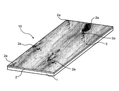
In the embodiment in fig. 2, the substrate 1 comprises a wood-based board
such as plywood, HDF, MDF, particleboard etc. In this embodiment the veneered
element 10 may be a building panel or a furniture component. If the veneered
element 10 is a floor or wall panel, the floor or wall panel may be provided
with a
15 mechanical locking system for joining with an adjacent floor or wall
panel. If the
veneered element 10 is a furniture component for a drawer, shelf or other
furniture,
the furniture may be provided with a mechanical locking system for joining
with
another part of the drawer, shelf or furniture component.
The veneered element 10 may be provided with decorative grooves or
20 bevels. The decorative grooves or bevels may be extending into the sub-
layer 2 such
that the sub-layer 2 is visible form the top surface of the veneered element.
The
decorative groove or bevel may be arranged adjacent an edge of the veneered
element provided with the mechanical locking system. By providing a decorative
groove extending into the sub-layer 2, a ship-decking appearance may be
obtained.
In the embodiment in fig. 2, the sub-layer 2 has permeated through the
veneer layer 3 in some portions of the veneer layer 3 where the resistance of
the
veneer has been lower, for example as in cracks, holes and cavities of the
veneer
layer, but to a lower degree through other parts of the veneer layer 3.
Portions 2a of
the sub-layer 2 are visible on the surface of the veneer layer 3 as shown in
fig. 2. The
permeation of the sub-layer 2 forms an irregular design of the veneer.
Fig. 3 shows a cross-section of the veneered element 10 in more detail. Fig. 3
illustrates in more detail how portions 2a of the sub-layer 2 have permeated
through
the veneer layer 3 such that the portions 2a of the sub-layer 2 are visible
from an
exposed surface of the veneer layer 3. Fig. 3 illustrates that the sub-layer 2
has
permeated through the veneer layer 3 and filled holes 6 of veneer such that
portions
2a of the sub-layer 2 are visible through the veneer layer 3. The hole 6 may,
as in fig.
3, be a knot. Fig. 3 also illustrates that the sub-layer 2 has permeated
through the
CA 02934896 2016-06-22
WO 2015/105456 PCT/SE2015/050008
21
veneer layer 3 and filled cracks 7 in the veneer such that portions 2a of the
veneer
layer 3 are visible from the upper surface of the veneer layer 3. Furthermore,
fig. 3
shows that portions 2a of the sub-layer 2 have permeated through pores 8 of
the
veneer layer 3 such that portions 2a of the sub-layer 2 are visible on the
upper
surface of the veneer layer 3. In the embodiment shown in fig. 3, the
substrate 1
comprises a wood based board such as plywood, HDF, MDF, particleboard etc. The
veneered element 10 is also provided with a balancing layer 5 arranged on a
second
surface 9 of the substrate 1, opposite the sub-layer 2. The balancing layer 5
may be a
powder based balancing layer being applied as a powder. The powder based
balancing layer may comprise wood particles such as lignocellulosic and/or
cellulosic
particles and a binder, preferably a thermosetting binder such as an amino
resin.
The balancing layer may be a resin impregnated paper, preferably impregnated
with
a thermosetting binder.
In fig. 4, also showing a veneered element 10 of the above described type
wherein the substrate 1 comprising a wood based board such as plywood, HDF,
MDF, particleboard etc. Also in this embodiment the veneered element 10 may be
a
building panel or a furniture component, and may be provided with a mechanical
locking system. However, in this embodiment, compared to the embodiment shown
in fig. 2, permeation of the sub-layer 2 is more uniform through the veneer
layer 3
such that a more regular design of the veneer layer 3 is obtained. This may be
achieved by applying a uniform pressure, and by providing a veneer layer 3
having a
uniform porous structure and/or uniform thickness.
Fig. 5 shows an embodiment of the veneered element 10 of the above
described type wherein the substrate 1 comprises a paper or a sheet. The
substrate
1 forms a carrier for the veneer layer 3 and the sub-layer 2. The veneered
element
10 according to this embodiment may be bendable and/or flexible. Thereby, post-
forming of the veneered element 10 is possible. The veneered element 10 may be
adhered to another element in a later operation. The veneered element 10 may
form a surface of, for example, a furniture component. In one embodiment, the
substrate is a conveyor, and the veneered element 10 is removed from the
conveyor
after heat and pressure have been applied.
It is contemplated that there are numerous modifications of the
embodiments described herein, which are still within the scope of the
invention as
defined by the appended claims.
It is contemplated that the sub-layer may not directly contact the substrate,
but an intermediate layer arranged between the substrate and the sub-layer may
be
provided.
CA 02934896 2016-06-22
WO 2015/105456 PCT/SE2015/050008
22
It is also contemplated that the building panel may be provided with a
second veneer layer (not shown) of the above described type applied in the
same
manner as described above. A sub-layer of the above described type is applied
on a
second surface of the substrate of the above described type. The second
surface of
the core faces away from the veneer layer described above with reference to
figs. 1-
4. In this embodiment, the veneer layer described above with reference to
figs. 1-4
is considered as a first veneer layer, and the second veneer layer is arranged
oppositely the first veneer layer. A design of the second veneer layer is
controlled
by determining level of permeation of the sub-layer through the second veneer
layer
as described above with reference to figs. 1-5.
Examples
Example 1:
400 g/m2 of a powder mixture, comprising 40 wt-% wood fibres, 10 wt-%
aluminium
oxide (Alodur ZWSK 180-ST), 49.5 wt-% melamine formaldehyde resin (Kauramin
773) and 0.5 wt-% of carbon black (Printex 60), was scattered on a 10.0 mm HDF
board for forming a sub-layer. The powder layer forming the sub-layer was
sprayed
with 20 g/m2 of an aqueous solution of a release agent (PAT-660). A 0.6 mm oak
veneer layer was positioned on the sub-layer prior to pressing the assembly in
a
short cycle press for 30 seconds at 40 bar with a press plate temperature of
160 C.
The resulting product was a veneered HDF having pores and cracks in the veneer
layer filled with the cured powder mixture of the sub-layer.
Example 2:
800 g/m2 of a powder mixture, comprising of 40 wt-% wood fibres, 10 wt-%
aluminium oxide (Alodur ZWSK 180-ST), 49.5 wt-% melamine formaldehyde resin
(Kauramin 773) and 0.5 wt-% of carbon black (Printex 60), was scattered on a
10.0
mm HDF board for forming a sub-layer. The powder layer forming the sub-layer
was
sprayed with 20 g/m2 of an aqueous solution of a release agent (PAT-660). A
0.6 mm
oak veneer was positioned on the sub-layer prior to pressing the assembly in a
short
cycle press for 30 seconds at 40 bar with a press plate temperature of 160 C.
The
resulting product was a veneered HDF having cracks and an increased amount of
pores in the veneer layer filled with the cured powder mixture of the sub-
layer in
comparison with the product of example 1.
CA 02934896 2016-06-22
WO 2015/105456 PCT/SE2015/050008
23
Example 3:
400 g/m2 of a powder mixture, comprising 17.5 wt-% wood fibres, 17.5 wt-%
mineral fibres 10 wt-% aluminium oxide (Alodur ZWSK 180-ST), 52,5 wt-%
melamine
formaldehyde resin (Kauramin 773) and 0.5 wt-% of carbon black (Printex 60),
was
scattered on a 10.0 mm HDF board for forming a sub-layer. The powder layer
forming the sub-layer was sprayed with 20 g/m2 of an aqueous solution of a
release
agent (PAT-660). A 0.6 mm oak veneer was positioned on the sub-layer prior to
pressing the assembly in a short cycle press for 30 seconds at 40 bar with a
press
plate temperature of 160 C. The resulting product was a veneered HDF having
cracks and a decreased amount of pores in the veneer layer filled with the
cured
powder mixture of the sub-layer in comparison with the product of example 1.
Example 4:
400 g/m2 of a powder mixture, comprising 10 wt-% aluminium oxide (Alodur ZWSK
180-ST), 89.5 wt-% melamine formaldehyde resin (Kauramin 773) and 0.5 wt-% of
carbon black (Printex 60), was scattered on a 10.0 mm HDF board for forming a
sub-
layer. The powder layer forming the sub-layer was sprayed with 20 g/m2 of an
aqueous solution of a release agent (PAT-660). A 0.6 mm oak veneer was
positioned
on the sub-layer prior to pressing the assembly in a short cycle press for 30
seconds
at 40 bar with a press plate temperature of 160 C. The resulting product was a
veneered HDF having cracks and an increased amount of pores in the veneer
filled
with the cured powder mixture of the sub-layer in comparison with the product
of
the example 1.
Example 5:
400 g/m2 of a powder mixture, comprising 40 wt-% wood fibres, 10 wt-%
aluminium
oxide (Alodur ZWSK 180-ST), 49.5 wt-% thermoplastic binder (Vinnapas 5010 N)
and
0.5 wt-% of carbon black (Printex 60), was scattered on a 10.0 mm HDF board
for
forming a sub-layer. The powder layer forming the sub-layer was sprayed with
20
g/m2 of an aqueous solution of a release agent (PAT-660). A 0.6 mm oak veneer
was
positioned on the sub-layer prior to pressing the assembly in a short cycle
press for
30 seconds at 40 bar with a press plate temperature of 160 C. The resulting
product
was a veneered HDF having a decreased amount of pores and cracks in the veneer
layer filled with the cured powder mixture compared to the product of example
1.
CA 02934896 2016-06-22
WO 2015/105456 PCT/SE2015/050008
24
Example 6:
400 g/m2 of a liquid mixture, comprising 45 wt-% water, 10 wt-% aluminium
oxide
(Alodur ZWSK 180-ST), 44.5 wt-% melamine formaldehyde resin (Kauramin 773) and
0.5 wt-% of carbon black (Printex 60), was applied on a 10.0 mm HDF board for
forming a sub-layer. A 0.6 mm oak veneer was positioned on the liquid layer
forming
the sub-layer prior to pressing the assembly in a short cycle press for 30
seconds at
40 bar with a press plate temperature of 160 C. The resulting product was a
veneered HDF having pores and cracks in the veneer layer filled with the cured
mixture.