Note: Descriptions are shown in the official language in which they were submitted.
SELF ALIGNING CLIP TRENCH FOR A FOAM PAD
CROSS-REFERENCE TO RELATED APPLICATIONS
[0001] This application claims priority based on United States
Provisional Patent
Application No. 62/187,522 entitled "SELF ALIGNING CLIP TRENCH FOR A FOAM
PAD" filed July 1, 2015.
BACKGROUND OF THE INVENTION
1. Field of the Invention
[0002] The present invention relates to an assembly for attaching
and securing a
vehicle seat trim cover to a vehicle seat foam pad. More particularly, the
present invention
relates to a self-aligning clip trench for attaching the trim cover to the
foam pad of the
vehicle seat.
2. Description of Related Art
[0003] Vehicle seats typically include a seat back and a seat
cushion. The seat
back and seat cushion each include a frame for supporting a cellular, foam
pad, and a trim
cover which at least partially covers the foam pad. A variety of conventional
attachment
methods, including but not limited to hog-rings, hook and loop, and mechanical
clips, are
currently used to attach the trim cover to the foam pad. A common problem with
each of
the aforementioned conventional attachment methods, as well as many of the
other well-
known methods, is ergonomic assembly. An operator typically has to manually
guide an
attachment feature disposed on an underside of the trim cover to engage a
corresponding
attachment feature located on the foam pad.
[0004] For Example, Figure 1 details the well-known method of
attaching a trim
cover 10 to a foam pad 12 using hog-rings 14. The [hog-ring] method includes
providing
a number of preformed wires 16 attached to portions 12a of the foam pad 12
where small
rings or hooks, dubbed hog-rings 14 in the industry, are crimped to fixedly
attach the trim
cover 10 to the foam pad 12. During installation, an installer uses a tool to
assist with
engaging the hog-rings 14 with the preformed wires 16 wherein the hog-rings 14
can
thereafter be crimped in place to attach the trim cover 10 to the foam pad
1
CA 2935060 2020-02-14
=
CA 02935060 2016-07-04
12. Connecting the hog-rings 14 to the preformed wires 16 is ergonomically
difficult
and requires substantial effort by the installer. Additionally, the hog-ring
method does
not include the use of an alignment mechanism to ensure proper positioning of
the trim
cover 10 with the preformed wires 16.
[0005] Figure 2 details another well-known method of attaching a trim cover
20
to a foam pad 22 involving the use of hook and loop fasteners 24. The hook and
loop
fasteners 24 include a strip of material including hook portions 28 and a
strip of material
including loop portions 26. The strip of material including the loop portions
26 is
mounted to the trim cover 20 and the strip of material including the hook
portions 28 is
mounted to a corresponding area of the foam pad 22. During installation, the
loop
portions 26 are overlaid upon the hook portions 28 wherein they engage to
secure the
trim cover 20 to the foam pad 22. However, hook and loop fasteners 24 are
expensive;
can become detached from each other over extended periods of use; and do not
include
an alignment mechanism, which causes the hook and loop fasteners 24 to be more
prone
to misalignment.
[0006] Figure 3 details yet another well-known method of attaching a trim
cover
30 to a foam pad 32 involving the use of mechanical clips 34. The mechanical
clips 34
include a pair of spaced apart legs 36 that extend outwardly from a base 38 to
form a
cavity 40 therebetween. The legs 36 include a pair of upper hooks or barbs 42
that face
toward each other, thereby defining a funnel 44 which leads into a cavity 40.
The trim
cover 30 includes a bead 46 attached thereto. Legs 36 are spaced such that the
bead 46
can pass therebetween, becoming entrapped in the cavity 40 by the hooks or
barbs 42,
which prevents outward movement of the bead 46 from the cavity 40. However,
the
mechanical clip 34 does not include an alignment mechanism. During assembly,
this
quite often results in the bead 46 being misaligned and positioned incorrectly
between
the mechanical clip 34 and a trench 48 formed in the foam pad 32. The trench
48 is
formed during the process of molding the mechanical clips 34 into the foam pad
32,
which is further detailed below.
[0007] Figure 4 details a known process of embedding the mechanical clip 34
into the foam pad 32. During this process, a foam mold tool (partially shown)
is used to
2
CA 02935060 2016-07-04
form the foam pad 32 and embed the mechanical clip 34 therein. The foam mold
tool
includes a first mold portion (not shown) and a second mold portion 50. The
second
mold portion 50 includes a contoured projection 52 having openings 54 formed
therealong. The openings 54 are disposed to receive the pair of legs 36 of the
mechanical clips 34. Liquid foam material is poured into the foam mold tool
and
expands about the contoured projection 52 of the second mold portion 50
thereby
embedding the mechanical clip 34 into the foam pad 32 being formed. As the
liquid
foam material is poured into the second mold portion 50 and expanded about the
contoured projection 52 in forming the foam pad 32, a trench 48, in the shape
of the
contoured projection 52, is formed into the foam pad 32. The trench 48 creates
a
cumbersome and unfortunate potential for the bead 46 to become misaligned with
the
foam pad 32 during assembly of the trim cover 30 to the foam pad 32. Many
times, the
person performing the assembly is unaware of such a misalignment which results
in the
trim cover 30 either becoming detached from the foam pad 32 or the trim cover
30
simply not being fully taught with the foam pad 32.
j00081 There are numerous methods and systems which attempt, with varying
degrees of success, to address misalignment of the trim cover with the foam
pad during
automobile seat assembly. The exemplary embodiments detailed herein addresses
the
issues associated with the previous methods by providing a fail-proof method
of aligning
and securely attaching a trim cover to a foam pad, as detailed herein below.
SUMMARY OF THE INVENTION
100091 An exemplary embodiment includes a method for embedding a
mechanical clip into a foam pad of a seat and for creating a self-aligning
clip trench in
the foam pad. The exemplary method involves placement of the mechanical clip
in a
foam mold tool which is used in the molding process of the foam pad. A foam
mold rail
herein constitutes only one portion of the foam mold tool (partially shown).
Other
portions of the foam mold tool are eliminated for simplicity. The exemplary
foam mold
rail is configured to form the self-aligning clip trench, wherein the geometry
of the self-
aligning clip trench ensures the proper placement of a trim cover with respect
to the foam
pad.
3
CA 02935060 2016-07-04
[0010] The foam mold rail may be integrally formed within one piece of a
traditional two-piece foam mold tool (not shown). Alternatively, the foam mold
rail may
serve as a third piece or as an insert that is inserted within the traditional
two-piece foam
mold tool for forming a foam pad. The foam mold rail includes a pedestal and a
trench
forming section. The trench forming section is contoured to form a shaped
trench in the
foam pad and further includes a plurality of notches spaced intermittently
along a tip
thereof and a plurality of slots similarly spaced intermittently along
opposing sides
thereof. The notches and slots are designed to locate a plurality of
mechanical clips used
to fasten the trim cover to the foam pad. The notches and slots also further
assist with
aligning the mechanical clips both vertically and axially along the length of
the trench
forming section thereby ensuring that the mechanical clips used to retain an
attachment
feature of the trim cover is maintained in position during pouring and
expansion of a
liquid foam material into the foam mold tool and during the overall molding
process.
[0011] During assembly of the trim cover with the foam pad, the exemplary
self-
aligning clip trench that is formed in the foam pad advantageously self-aligns
the trim
cover with respect to the mechanical clips which are now positioned in the
foam pad. As
such, any previously known concerns are alleviated with respect to the
attachment
feature of the trim cover being mistakenly positioned in a space between the
foam pad
trench and the legs of the mechanical clips, or with respect to the trim cover
being
misaligned in any manner with the mechanical clips or the foam pad during seat
assembly.
BRIEF DESCRIPTION OF THE DRAWINGS
[0012] Advantages of the present disclosure will be readily appreciated as
the
same becomes better understood by reference to the following detailed
description when
considered in connection with the accompanying drawings wherein:
[0013] Figure 1 is a perspective view of a conventional method of attaching
a
trim cover to a foam pad wherein the method involves hog-rings;
4
CA 02935060 2016-07-04
100141 Figure 2 is a perspective view of another conventional method of
attaching a trim cover to a foam pad wherein the method involves hook and loop
fasteners;
[0015] Figure 3 is a cross-sectional view of yet another conventional
method of
attaching a trim cover to a foam pad wherein the method involves mechanical
clips:
[0016] Figure 4 is a perspective view of the mechanical clip and a portion
of a
mold used in the conventional method of attaching the trim cover to the foam
pad;
[0017] Figure 5 is a perspective view of an exemplary foam mold rail
according
to one aspect of the invention;
[0018] Figure 6 is a perspective view of the foam mold rail of Figure 5
with a
mechanical clip attached thereto prior to the molding process;
[0019] Figure 7 is a cross-sectional view of a self-aligning clip trench
formed in a
foam pad after the molding process wherein the mechanical clip is embedded
therein;
[0020] Figure 8 is a cross-sectional view detailing the method of placing
the trim
cover with respect to the self-aligning clip trench formed in the foam pad as
shown in
Figure 7;
[0021] Figure 9A is a cross-sectional view detailing the self-aligning
feature of
the self-aligning clip trench method; and
[00221 Figure 9B is a cross-sectional view of an alternative self-aligning
clip
trench formed in a foam pad after the molding process wherein the exemplary
mechanical clip is embedded therein.
DETAILED DESCRIPTION OF THE PREFERRED EMBODIMENTS
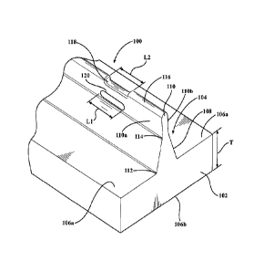
[00231 Referring to Figures 5 and 6, an exemplary embodiment of a foam mold
rail 100 includes a pedestal 102 and a trench forming section 104. The
pedestal 102 has
an upper surface 106a and a lower surface 106b defining a predetermined
thickness T
therebetween. If the foam mold rail 100 is integrally formed within one piece
of a
CA 02935060 2016-07-04
traditional two-piece foam mold tool, then upper surface 106a would coincide
with the
A-surface of the foam mold tool. The trench forming section 104 is positioned
along the
pedestal 102 and extends perpendicularly with respect to the pedestal 102,
outwardly
away from the upper surface 106a of the pedestal 102. The trench forming
section 104 is
contoured to include a funnel shaping segment 108 and a trench segment 110.
The upper
surface 106a of the pedestal 102 extends outwardly away from the trench
forming
section 104 on opposing sides thereof. The funnel shaping segment 108 includes
a
widened end 112 and a narrowed end 114. The widened end 112 is connected to
the
upper surface 106a of the pedestal 102. The funnel shaping segment 108 tapers
linearly
from the widened end 112 towards the narrowed end 114 in a direction away from
the
upper surface 106a of the pedestal 102. The trench segment 110 is connected to
the
narrowed end 114 of the funnel shaping segment 108. The trench segment 110
includes
a distal tip 116 wherein the tip 116 includes a plurality of spaced notches
118 formed
therealong. The notches 118 are disposed longitudinally along the trench
segment 110
and are designed to locate a plurality of mechanical clips 122 used to fasten
a trim cover
150 to a foam pad 140, as further described below. The trench segment 110
further
includes elongated slots 120 formed in opposing sides 110a, 110b of the trench
segment
110. The slots 120 are formed longitudinally about the opposing sides 110a,
110b of the
trench segment 110, and are located directly below the notches 118 formed in
the tip
116. The slots 120 generally have a length Ll that need not correspond to a
length L2 of
the notches 118. The notches 118, in combination with the slots 120, assist
with aligning
the mechanical clips 122 to ensure that the mechanical clips 122 are retained
in position
both vertically and axially along the length of the trench forming section 104
during the
foam pad 140 forming process.
[0024] Regarding
Figures 6 and 7, the mechanical clips 122 include a base 124
having a top surface 126 and a bottom surface 128. A pair of legs 130 is
connected to
and extends from the top surface 126 of the base 124. The notches 118 and
slots 120
have widths and lengths that are predetermined so that the mechanical clips
122 may be
securely positioned on the trench forming section 104. The base 124 may
include ribs
134 which provide additional strength to the base 124 during the molding
process and
during general use of the mechanical clips 122 while disposed in the seat.
When
positioning the clips 122 upon the trench forming section 104, the legs 130 of
the
6
CA 02935060 2016-07-04
mechanical clips 122 straddle the tip 116 of the trench forming section 104
such that a
mid-section 136 is positioned within the notches 118. With the legs 130
already
straddling the trench segment 110, and just prior to positioning the mid-
section 136 of
the base 124 within the notch 118, the pair of legs 130 are slid into the
respective slots
120 disposed on opposing sides 110a, 110b of the trench segment 110. The pair
of legs
130 includes retaining members 132 connected to the legs 130 wherein the
retaining
members 132 are configured to extend at an angle with respect to the legs 130.
Retaining members 132 further assist with retaining the legs 130 within the
slots 120 and
include a first end 132a and a second end 132b. The second end 132b is
retained in the
slot 120 of the trench segment 110.
100251 During the
molding process, the foam mold rail 100, which is integrally
formed within one piece of a traditional two-piece foam mold tool, contains
the attached
mechanical clips 122 and is joined with the other piece of the foam mold tool
(not
shown). In another aspect, the foam mold rail 100 may serve as a third piece
or as an
insert for the two-piece foam mold tool. Once the foam mold rail 100, with the
mechanical clips 122 secured thereto, is joined to form the foam mold tool,
liquid foam
material or other similar expandable material is poured into the mold. The
foam mold
rail 100 allows for the plurality of mechanical clips 122 to be embedded in
the foam pad
140 while simultaneously forming a self-aligning clip trench 138 in the foam
pad 140.
The mechanical clips 122 may be formed from a polymer material that may be
particularly suited to provide good adhesion and chemical reaction bonding
with the
foam pad 140. Acceptable polymer materials for the mechanical clips 122
include, but
are not limited to, nylon, polyester, polycarbonate, polyacetate or any other
durable
thermoplastic having desired mechanical properties. The foam pads 140 are
typically
polyurethane or isoeyanate-based foam. The material of either the mechanical
clips 122
or the foam pad 140 must be selected so as to have the capability of surviving
temperature and environmental variations over an expected range, as well as to
have the
capability of promoting bonding and/or adhesion to one another. As the foam or
other
similar material expands, it disperses and spreads about the foam mold tool to
fully
encompass the foam mold rail 100 and the attached mechanical clips 122. In
doing so,
the first end 132a of the retaining members 132 becomes embedded within the
foam pad
140 while the second end 132b of the retaining members 132 is exposed and
projects,
7
CA 02935060 2016-07-04
untampered by the foam or other similar material, into the self-aligning clip
trench 138
formed by the trench forming section 104.
[00261 In reference to Figure 7, once the expanded foam or other similar
material
is set and cured, the foam pad 140 is removed from the foam mold tool and the
self-
aligning clip trench 138 is formed, thereby exposing the second ends I32b of
the
retaining members 132. The foam pad 140 is made with the exemplary self-
aligning clip
trench 138 and mechanical clips 122 molded therein. The self-aligning clip
trench 138
includes a funnel 138a that corresponds with the funnel shaping segment 108
and a
trench 138b that corresponds with the trench segment 110. The funnel 138a
tapers and
includes linear side walls 138e that extend from a widened opening 138c of the
funnel
13810 a narrowed opening 138d. The trench I38b is continuous in length and
width, and
extends from the narrowed opening 138d of the self-aligning clip trench 138 to
the upper
surface 126 of the base 124 of the mechanical clip 122. The second ends 132b
project
into the self-aligning clip trench 138 at about an intersection of the side
walls 138e and
the narrowed opening I38d wherein the angled orientation of side walls 138e of
the
funnel 138a and the projecting second end 132b of the retaining member 132,
assist in
permitting the self-alignment of the trim cover 150.
[0027] Referring to Figure 8, a portion of trim cover 150 may typically
include
two pieces of material joined together at a seam 158. The trim cover 150 may
also
include an attachment feature 152 connected thereto. The attachment feature
152
includes a rigid cylindrical member 154 enclosed by an attachment cover piece
156. The
rigid cylindrical member 154 can be made from a plastic, metal, or other
similar rigid
material. The rigid cylindrical member 154 is sized to pass between the
retaining
members 132 of the mechanical clips 122 and may be trapped thereafter, against
outward
movement therefrom, by the projecting second ends 132b of the retaining
members 132
in the trench 138b. The attachment cover piece 156 is retained, via a
stitching 160 or
other attachment means, against the seam 158 formed in the trim cover 150.
Collectively, the diameter of the rigid cylindrical member 154 and attachment
cover
piece 156 defines an outer diameter 162 that is approximately equal to the
width of the
narrowed opening 138d and trench 138b. The attachment feature 152 can be
constructed
of beaded duon, as is commonly known in the art.
8
CA 02935060 2016-07-04
[0028] In reference to Figure 9A, during the process of attaching the trim
cover
150 to the foam pad 140, an installer needs only to apply a force F to a top
side 150a of
the trim cover 150 at the seam 158 or at approximately near a position where
the two
trim cover pieces 150 are joined together. The force F causes the rigid
cylindrical
member 154 to move down into the funnel 138a where the side walls 138e guide
the
rigid cylindrical member 154 therealong and forces the rigid cylindrical
member 154 to
self-align with the narrowed opening 138d and trench 138b. As a result of the
force F.
the rigid cylindrical member 154, now being self-aligned, is pressed down
between the
projecting second ends 132b of the retaining members 132. In response to the
rigid
cylindrical member 154 being pressed down between the projecting second ends
132b of
the retaining members 132, the pressure from the force F imposed thereon
triggers the
retaining members 132 to spread, thereby allowing the rigid cylindrical member
154 to
pass therebetween.
[0029] Once the rigid cylindrical member 154 passes fully between the
projecting second ends 132b of the retaining members 132, the rigid
cylindrical member
154 is guided by a portion 164 of the foam pad 140 that consequently, after
the molding
process, helps to form side walls 166 of the trench 138b. Side walls 166 of
the trench
138b ensure that the rigid cylindrical member 154 self-aligns within the
trench I38b, and
is mechanically retained therein beneath the projecting second ends 132b of
the retaining
members 132. While the bases 124 of the mechanical clips 122 are embedded and
locked into the foam pad 140 as a result of the molding process, the bases 124
of the
mechanical clips 122 are disposed beneath the trench 138b and serves as a
bottom of the
trench 138b. The length of the attachment cover piece 156 is selected such
that once the
rigid cylindrical member 154 self-aligns within the trench 138b, and is
mechanically
retained therein beneath the projecting second ends 132b of the retaining
members 132,
the trim cover 150 is subsequently pulled taut against the foam pad 140. The
funnel
138a provides a space for any trim cover 150 seam salvage to be stored
comfortably
therein without producing a noticeable and unsightly bulge in the top side
150a of the
trim cover 150. The rigid cylindrical member 154 is sufficiently retained
against the
projecting second ends 132b of the retaining members 132 with there being
minimal
potential for the rigid cylindrical member 154 to be setback into the trench
I38b.
Conventional methods typically require an installer to manually guide an
attachment
9
CA 02935060 2016-07-04
feature from the underside of the trim cover in order to engage a
corresponding
attachment feature located in the foam pad. However, in this manner, the
installer guides
the self-aligning feature from the top side of the trim cover thereby removing
the
awkwardness associated with having to maneuver attachment from the underside
of the
trim cover. Additionally, the requirement for additional tools, aligning
and/or adjusting
is eliminated.
[0030] Regarding Figure 9B, an alternative exemplary self-aligning clip
trench
238 includes a funnel 238a and a trench 238b. The funnel 238a includes a
curved taper
wherein side walls 238e of the funnel 238 comprises a curved contour which
extends
from a widened opening 238c to a narrowed opening 238d. The trench 238b is
also
continuous in length and width, and extends from the narrowed opening 238d of
the self-
aligning clip trench 238 to the upper surface 126 of the base 124 of the
mechanical clip
122. The second ends I32b project into the self-aligning clip trench 238 at
about an
intersection of the side walls 238e and the narrowed opening 238d wherein the
curved
orientation of side walls 238e of the funnel 238a and the projecting second
end 132b of
the retaining member 132, assists in permitting the self-alignment of the trim
cover 150.
[0031] The method of attaching the trim cover 150 to the foam pad 140 using
the
self-aligning clip trench 238 of Figure 9B is similar to the exemplary method
for
attaching the trim cover 150 to the foam pad 140 using the self-aligning clip
trench 138
detailed in Figure 9A. The exception being that, upon application of the force
F, the
rigid cylindrical member 154 is guided along the curved side walls 238e
wherein the
rigid cylindrical member 154 is self-aligned with the narrowed opening 238d
and trench
238b. All other molding and installation steps are the same as that detailed
for self-
aligning clip trench 138.
[0032] The invention has been described in an illustrative manner, and it
is to be
understood that the terminology used is intended to be in the nature of words
of
description rather than limitation. Many modifications and variations of the
present
invention are possible in light of the above teachings. It is, therefore, to
be understood
that within the scope of the appended claims, the invention may be practiced
other than
as specifically enumerated within the description.