Note: Descriptions are shown in the official language in which they were submitted.
CA 02935165 2016-06-27
W02015/102663 PCMJS2014/035408
UNI-DIRECTIONAL RIGIDIFIER AND METHOD
FIELD OF THE INVENTION
The invention herein pertains to tension members and
particularly pertains to arcuate spring members for use in sofa
beds.
DESCRIPTION OF THE PRIOR ART
AND OBJECTIVES OF THE INVENTION
Various types of tension members have been used in furniture
seats and sofa mattresses for many years. Coil, sinuous, and flat
or leaf springs have often been employed to provide comfort for the
user. A foldable mattress that employs springs must carefully
balance the tension so that the user is comfortable both while
sitting with the mattress folded in sofa mode and while the user is
in a prone position with the mattress unfolded or extended in bed
mode. A sofa mattress that is either "too hard" or "too soft"
brings discomfort and causes loss of sleep. Therefore to address
the problem of providing the optimum tension and comfort in a sofa
mattress, the present invention was conceived and one of its
objectives is to provide a uni-directional rigidifier formed from
an arcuate tension member which can be easily fitted and attached
within a foldable mattress for a sofa bed.
It is another objective of the present invention to provide an
elongated tension member for a sofa bed mattress which can lock or
close to stiffen when in the bed mode and which will provide
flexing when in the sofa mode.
1
CA 02935165 2016-06-27
WO 2015/102663 PCT/US2014/035408
It is still another objective of the present invention to
provide a tension member which includes a series of lateral slits
therealong to provide exceptional locking and stiffening ability.
It is yet another objective of the present invention to
provide a tension member which is conventionally stamped and formed
from coated sheet steel.
It is a further objective of the present invention to provide
an elongated tension member which can be easily affixed within a
sofa bed mattress for improved comfort in both the sofa and bed
modes.
It is still a further objective of the present invention to
provide a tension member which is relatively inexpensive to
manufacture and install.
It is yet a further objective of the present invention to
provide an elongated tension member having a U-shaped cross-section
with lateral slits therein capable of flexing in a single
direction.
Various other objectives and advantages of the present
invention will become apparent to those skilled in the art as a
more detailed description is set forth below.
SUMMARY OF THE INVENTION
The aforesaid and other objectives are realized by providing
uni-directional rigidifiers formed from arcuate tension members
which extend longitudinally and have a U-shaped cross-section. In
the upright position as a load is applied such as with an
2
CA 02935165 2016-06-27
WO 2015/102663 PCT/US2014/035408
individual sitting on the folded mattress in the sofa mode, the
tension members flex and the lateral slits open for seating
comfort. When the mattress is unfolded in the usual bed mode the
tension members are inverted and when a load is applied such as
when an individual lays on the unfolded mattress, the lateral slits
therealong close and therefore stiffen to prevent further flexing.
Thus the tension members provide the best support and comfort for
both sofa seating and bed modes.
The method of use described herein further demonstrates the
benefits and advantages of the arcuate tension member. The tension
member is formed with a plurality of lateral slits which allow
flexing when pressure is applied to the tension member, such as
while in the sofa mode. A sofa mattress can be fitted with a
suitable number of tension members, such as by attachment to the
spring assembly, or otherwise contained within the sofa bed
mattress. Unfolding the mattress for use in the bed mode presents
the tension members in an inverted configuration whereupon applying
a load (pressure) to the mattress causes the slits to close,
stiffening the mattress for the user.
BRIEF DESCRIPTION OF THE DRAWINGS
Fig. 1 shows the elongated, arcuate tension member of the
invention in an upright, relaxed perspective view;
Fig. 2 pictures the tension member as seen in Fig. 1 in a
right side elevational view depicting the elongated arc, the left
side elevational view being a mirror image thereof;
Fig. 3 depicts a right end view of the tension member as shown
in Fig. 2, the left end view being a mirror image thereof;
3
CA 02935165 2016-06-27
W02015/102663 PCT/US2014/035408
Fig. 4 demonstrates a top view of the tension member as shown
in Fig. 2;
Fig. 5 illustrates a bottom view of the tension member as
shown in Fig. 4;
Fig. 6 features a cross-sectional view of the tension member
generally as along lines 6-6 of Fig. 4;
Fig. 7 shows in schematic fashion the flexing of the tension
member as shown in Fig. 2 when a load is applied;
Fig. 8 illustrates the tension member in an inverted posture
with the slits closed due to the applied load;
Fig. 9 depicts a schematic side elevational view of a typical
foldable mattress of a sofa bed in the sofa mode with tension
members positioned within the mattress; and
Fig. 10 demonstrates the foldable mattress of Fig. 9 in an
extended or unfolded posture in the bed mode with the inverted
tension members shown therein.
DETAILED DESCRIPTION OF THE PREFERRED
EMBODIMENT AND OPERATION OF THE INVENTION
For a better understanding of the invention and its operation,
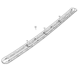
turning now to the drawings, Fig. 1 illustrates a perspective view
of a preferred uni-directional rigidifiers presented as elongated
tension members 10 having a plurality of lateral slits 11 spaced
therealong. In the side view as shown in Fig. 2, slits 11 are only
slightly open when tension member 10 is in its relaxed, arcuate
configuration. Openings 12 allow for screws, bolts, wires,
4
CA 02935165 2016-06-27
WO 2015/102663 PCT/US2014/035408
springs, zip ties or other fasteners to be used to affix tension
member 10 to the spring assembly inside mattress 21, cushion or the
like as shown schematically in Figs. 9 and 10. Tension member 10
includes opposing lips 13, 13' which are relatively flat and act as
top edges along the sides of U-groove 14 as seen in Figs. 3 and 6.
In Fig. 5 which portrays the bottom view of tension member 10, open
slits 11 are easily seen though tension member 10 is not under
pressure such as by the weight of a user. As seen in Figs. 4 and
5, slits 11 include apertures ha on each end which are in
communication therewith and provide pressure relief to tension
member 10 as slits 11 close and open during use to prevent damage
such as bending, creasing, stress fractures or the like to the
surrounding edges.
Preferred tension member 10 has a U-shaped cross-section as
seen along lines 6-6 of Fig. 4 and is formed such as by a
conventional stamping process from usual metal such as a thin
coated steel. Tension member 10 is formed from twenty (20) gauge
(0.8 mm thick) coated steel although other thicknesses and
materials such as plastics, aluminum or composite materials if
suitable may be employed. Tension member 10 was created to provide
comfort to the user while extending the life of a mattress and as
such must be formed from a durable material which will sustain its
shape during repeated use over an extended time period. The
preferred length of tension member 10 is preferably twenty-two
inches (55.88 cm) with a width of one and a half inches (3.81 cm)
although other lengths and widths may be used, depending on the
particular application and specifications desired.
A plurality of tension members 10 can be positioned for
example in a foldable mattress of a sofa bed such as sofa bed 20.
For example, see co-pending application Serial No. 13/470,458 and
Serial No. 13/470,478.
As shown
in Figs. 9 and 10, sofa bed 20 includes a standard foldable
mattress 21 having at least lower or first section 22 and folded or
second section 23. As seen in Fig. 9 in the sofa mode, tension
members 10 are in an upright position in folded or second section
23 which is shown folded atop lower or first section 22 which
includes tension members 10 in an inverted position. Second
section 23 in Fig. 9 is shown directly below seat cushion 24. In
Fig. 9, if sofa bed 20 is used for seating and seat cushion 24
above mattress 21 is sat upon, upright tension member 10 in second
section 23 will flex and slits 11 as shown in Fig. 7 Will open
allowing some give (flexing) An mattress 21 providing comfort to
the user. Tension members 10 in lower or first mattress section 22
will stiffen due to the closure of slits 11 therealong (see Fig. 8)
as a load is applied, such as by sitting thereon to prevent further
downward movement.
In Fig. 10, sofa bed 20 is shown with seat cushions 24 removed
and foldable mattress 21 in its extended posture for use as a bed.
Tension members 10 in first section 22 and second section 23 are
positioned proximate the bottom of mattress 21 and are both
inverted as shown larger in Fig. 8. Thus, when a load is applied
to first section 22 or second section 23 such as a person laying
thereon, tension members 10 stiffen due to slits 11 closing as seen
in Fig. 8 thus stopping the flexion of tension members 10 to
provide a firm support.
As would be understood the upper portion of mattress 21 as is
conventional allows for some deformation when a user lays thereon.
However over time and extended, repeated use, the mattress and
spring assembly (not shown) begin to flatten or sag and can provide
6
CA 2935165 2019-06-14
CA 02935165 2016-06-27
WO 2015/102663 PCT/US2014/035408
an unstable, uncomfortable mattress for the user. By positioning
tension members 10 within sofa mattress 21, an additional
stiffening structure is provided to assist in supporting the spring
assembly/mattress and will prevent sagging and "bottoming out" of
the mattress as often occurs over time after repeated use. Tension
members 10 provide support not only for the user but also for the
mattress itself to maintain its posture and ultimately extend its
"shelf life".
In the method of use, one or more uni-directional rigidifiers
shown as tension members 10 are formed such as by usual stamping
from coated steel and installed in a suitable, conventional
foldable mattress such as mattress 21 for use such as in sofa bed
20 as illustrated in Figs. 9 and 10.
Foldable mattress 21 is
positioned as normal in sofa bed 20 with usual removable back and
seat cushions. As
seat cushions 24 are loaded or pressure is
applied such as by an individual (not shown) sitting thereon,
tension member 10 in second (upper) mattress section 23 flexes
(with slits 11 opening) to provide comfort to the user. Lower or
first mattress section 22 having tension member 10 inverted will
only slightly flex causing slits 11 to close preventing further
flexing. Next, when using sofa bed 20 as a bed, seat cushions 24
are removed and second section 23 which is hingedly joined to first
section 22 is unfolded or extended as seen in Fig. 10 whereby
tension members 10 in both first section 22 and second section 23
are inverted. Here, as a person lays upon mattress 21, the upper
portion would deform downwardly as is conventional however tension
members 10 in both first section 22 and second section 23 would
stiffen as a load or pressure is applied causing lateral slits 11
to close, thus effectively locking tension members 10 and
preventing further flexing or downward deformation of mattress 21.
Such placement allows for a firmer mattress providing comfort to
7
CA 02935165 2016-06-27
WO 2015/102663 PCT/US2014/035408
the user while also preventing sagging of the mattress. Although
not shown as would be understood a plurality of tension members 10
are evenly spaced in an asymmetrical and parallel relation
approximately five inches (12.7 cm) apart along the width of
mattress 21 for a total of six (6) tension members 10 in both first
and second sections 22, 23 respectively to provide additional
stiffening support to mattress 21.
The illustrations and examples provided herein are for
explanatory purposes and are not intended to limit the scope of the
appended claims.
8