Note: Descriptions are shown in the official language in which they were submitted.
CA 02935222 2016-07-06
EXERCISE DEVICE
BACKGROUND OF THE INVENTION
1. Field of the Invention
[00011 The present invention pertains to a suspended exercise device. More
particularly, the present invention pertains to a suspended exercise device
which a user places
his or her feet upon to exercise while sitting down.
2. Description of the Prior Art
[0002] The mental and physical health benefits of exercise are well known.
The
physical benefits include reduced risk of heart disease and high blood
pressure. Additionally,
extended periods of time spent working at a desk or studying may be harmful if
that activity is
an impediment to the amount of exercise that one can get each day. It has been
shown that
not moving while working or studying at a desk may cause postural fixity,
which is the static
loading of the musculoskeletal system. Postural fixity may cause back, neck,
shoulder and
other pain. Extended periods of time spend sitting at a desk can also lead to
obesity when
paired with a poor diet because the individual is simply not burning calories
to inactivity.
[0003] The mental health benefits of exercise include reduced depression
and anxiety,
and improved psychological well-being.
1 of 14
CA 02935222 2016-07-06
[0004] In the prior art there exists various exercise devices which can be
used with a
desk and/or a desk chair. However, each of these devices requires active
participation and
focus from the user. In this respect, these devices may be a distraction to
the user while the
user is attempting to Study or work. Thus, the act of exercising is still in
conflict with the
user's study or work.
[0005] There remains a need for an exercise device which can be used as an
"unconscious" device in which the user does not necessarily have to perform
active exercises
in order to reap the benefits of the device. This type of device would allow
the user to burn
calories while they are not actively exercising.
[0006] The present invention, as detailed hereinbelow, seeks to fill this
need by
providing a suspended footrest device which can be easily installed in any
suitable location
and used either actively or passively to provide movement and exercise to a
user in a seated
position.
SUMMARY OF THE INVENTION
[0007] The present invention provides a suspended footrest device
comprising: (a) a
pair of footrests; (b) a rigid elongated member having a pair of opposed ends
and a medial
section, each of the footrests being pivotally connected to a respective one
of the ends of the
elongated member; and (c) at least one a non-rigid suspension member having a
first end
connected to the rigid elongated member, and a second end connected to a fixed
location for
suspension of the footrest device therefrom.
2 of 14
CA 02935222 2016-07-06
[0008] Optionally, the suspended footrest device can include a ball-and-
socket joint
connected between each footrest and the respective end of the rigid elongated
member to
allow pivotal movement between each footrest and the rigid elongated member.
[0009] Optionally, the suspended footrest device can include a rotatable
turntable
connected between each footrest and the respective end of the rigid elongated
member to
allow rotational movement between each footrest and the rigid elongated
member.
[0010] Optionally, the first end of the suspension member is connected to
the medial
section of the elongated member.
[0011] The suspension member may be either elastic or inelastic.
[0012] The suspended footrest can also optionally include a damper
positioned
between each footrest and the respective end of the rigid elongated member for
dampening
the pivotal movement of the ball-and-socket joint.
[0013] Additionally, the suspended footrest device can include a rigid
elongated
support member having a first end and a second end. The first end is connected
to a chair,
and the second end is connected to the second end of the non-rigid suspension
member. The
footrests and the rigid elongated member are thus suspended by the rigid
elongated support
member and the non-rigid suspension member.
[0014] For a more complete understanding of the present invention,
reference is made
to the following detailed description and accompanying drawings. In the
drawings, like
reference characters refer to like parts throughout the views in which:
3 of 14
=
CA 02935222 2016-07-06
BRIEF DESCRIPTION OF THE DRAWINGS
[0015] FIG. 1 is a perspective view of a first embodiment of the present
invention
hereof;
[0016] FIG. 2 is a front view of the first embodiment of the present
invention;
[0017] FIG. 3 is an enlarged front view showing one embodiment of the
footrest being
pivotally connected to an end of the elongated member;
[0018] FIG. 4 is an enlarged front view showing another embodiment of the
footrest
being pivotally connected to an end of the elongated member; and
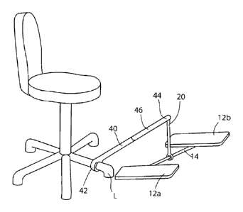
[0019] FIG. 5 is a perspective view showing a second embodiment of the
invention in
which the footrests are suspended directed from a support member that is
connected to the
=
user's chair.
DETAILED DESCRIPTION OF THE PREFERRED EMBODIMENT
[0020] In accordance with the present invention and as shown generally in
FIGS. 1 and
2, there is provided a suspended footrest device 10 comprising: (a) a pair of
footrests 12a,12b;
(b) a rigid elongated member 14 having a pair of opposed ends 16a,16b and a
medial section 18,
each of the footrests 12a,12b being pivotally connected to a respective one of
the ends 16a,16b
of the elongated member 14; and (c) a non-rigid suspension member 20 having a
first end 22
connected to the medial section 18 of the rigid elongated member 14, and a
second end 24
connected to a fixed location F for suspension of the footrest device 10
therefrom.
[0021] The footrests 12a,12b include a rigid base platform 26 and are
dimensioned to
receive the feet of the user. The base platform 26 is preferably thin and
planar and formed
from a substantially rigid material, such as wood, metal, a plastic polymer,
or the like. Each
=
4 of 14
CA 02935222 2016-07-06
=
footrest 12a,12b can optionally include a top layer 28 haying a pliable
material for cushioning
the user's feet which may or may not be contoured to the shape of a foot or a
shoe. Any
suitable type of pliable material that is well-known in the art can be used
for the top layer 28.
Optionally, each footrest 12a,12b can also include guide rails 30 along the
front, back, or sides
of each footrest 12a,12b to help the user keep his or her feet squarely
positioned on each
footrest 12a,12b.
[0022] In addition, each footrest 12a,12b can optionally include a bumper
(not shown)
formed from an elastomeric material along the front, back, or sides of the
each footrest 12a,12b
to keep the footrests 12a,12b from damaging any items or creating distracting
noise when the
footrests 12a,12b contact other items near the user.
[0023] The elongated member 14 is provided to connect the footrests
12a,12b to the
non-rigid suspension member 20. The elongated member 14 has a pair of opposed
ends
16a,16b and a medial section 18. Each of the footrests 12a,12b is pivotally
connected to a
respective one of the ends 16a,16b of the elongated member 14. The elongated
member 14 can
be formed from any suitable type of material, such as wood, metal, a plastic
polymer, and so
forth. The elongated member 14 can also have any suitable type of geometry,
such as being
solid or hollow, as well as having any suitable cross-sectional shape (e.g.,
triangular, rectangular,
circular, etc.). As discussed further below, the medial section 18 of the
elongated member 14 is
connected to the non-rigid suspension member 20 for suspending the footrests
12a,12b.
[0024] Each of the opposed ends 16a,16b of the elongated member 14 are
pivotally
connected to a respective one of the footrests 12a,12b. More specifically, a
bottom surface 32
of 14
CA 02935222 2016-07-06
of each base platform 26 is pivotally connected to the respective end 16a,16b
of the elongated
member 14.
[0025] The ends 16a,16b of the elongated member 14 can optionally each
include a
roller (not shown) to help elim.inate any damaging contact between the side of
the footrest
12a,12b or the end 16a,16b against the side of a desk or any other item.
[0026] Optionally, the footrests 12a,12b can also include means for moving
the
footrests 12a,12b out of the way of the user. For example, the footrests
12a,12b can include
magnets (not shown) at the front or bottom of each footrest so that the user
can store the
footrest device 10 against a magnetic surface which can be placed wherever as
desired by the
user.
[0027] As shown best in FIG. 3, the suspended footrest device 10 can
optionally
include a ball-and-socket joint 34 connected between each footrest 12a,12b and
the respective
end 16a,16b of the elongated member 14 to allow the pivotal movement. A ball-
and-socket
joint is well-known to those having ordinary skill in the art, and it provides
multi-axis
movement of the footrest with respect to the elongated member 14. More
specifically, and as
shown best in FIG. 1, the ball-and-socket joint 34 allows each footrest
12a,12b to pivot front-
to-back (about the x axis), side-to-side (about they axis), and also rotate
(about the z axis).
Any suitable type of ball-and-socket joint which is commercially available can
be used.
[0028] A damper 36 may optionally be positioned between each footrest
12a,12b and
the respective end 16a,16b of the elongated member 14 for dampening the
pivotal movement
of the ball-and-socket joint 34. Any suitable type of damper can be used. For
example, and
as shown in FIG. 4, the damper 36 can comprise a resiliently flexible
elastomer that surrounds
6 of 14
CA 02935222 2016-07-06
the ball-and-socket joint 34 and provides a moderate amount of resistance to
movement by
the ball-and-socket joint 34. And as shown in FIG. 3, the damper 36 can also
comprise a
plurality of elastomeric bumpers positioned at various locations around the
ball-and-socket
joint 34. The damper 36 can be positioned or designed so that it can dampen
the movement
of the ball-and-socket joint 34 in one axis, two axes, or three axes (i.e.,
the x,_y, and .z axes as
shown in FIG. 1). Preferably, the damper 36 dampens the movement of the ball-
and-socket
joint 34 along the x andy axes.
[0029] In addition to the ball-and-socket joint 34, a rotatable turntable
38 can be
connected between each footrest 12a,12b and the respective end 16a,16b of the
elongated
member 14 to allow rotational movement about the axis between each footrest
12a,12b and
the elongated member 14. Any suitable type of rotatable turntable can be used.
Preferably,
the rotatable turntable 38 includes a circular track and ball bearings to
facilitate smooth and
low-resistance rotational movement.
[00301 It is to be understood that either the ball-and-socket joint 34 or
the rotatable
turntable 38 can be used, as well as possibly both the ball-and-socket joint
34 and the
rotatable turntable 38 (as shown in FIGS. 3 and 4). When both are used, the
rotatable
turntable 38 is preferably connected directly to the bottom surface 32 of the
base platform 26
and the ball-and-socket joint 34 is preferably connected directly to the end
of the elongated
member 14. The bottom of the rotatable turntable 38 and the top (socket) of
the ball-and-
socket joint 34 are then connected directly to each other.
[0031] There is also provided at least one suspension member 20 having a
first end 22
connected to the elongated member 14, and a second end 24 connected to a fixed
location F
7 of 14
CA 02935222 2016-07-06
for suspension of the footrest device 10 therefrom. Preferably the first end
22 is connected to
the medial section 18 of the elongated member 14. The suspension member 20 can
be either
rigid or non-rigid, but preferably the suspension member 20 is non-rigid. When
the
suspension member 20 is rigid, it is flexibly connected at the ends 22,24 to
both the elongated
member 14 and the fixed location F to allow free-hanging movement of the
footrests 12a,12b
from the fixed location F. The suspension member 20 can be formed from any
suitable type
of material, including but not limited to, a rigid bar, a non-rigid cable, a
rope, a non-rigid
length of a polymeric material, a chain, and so forth.
[0032] The suspension member 20 may be either elastic or inelastic. That
is, the
suspension member 20 may be stretchable or have a fixed length, as well as
have different
elastic and inelastic sections.
[0033] The suspension member 20 may optionally include a quick-release
mechanism
(not shown) to allow the footrest device 10 to be quickly and easily removed
from the fixed
location F when it is desired. Any suitable type of quick-release mechanism
that is well-
known in the art can be used herewith, including a buckle, clasp, and so
forth.
[0034] As mentioned above, the second end 24 of the suspension member 20
is
connected to a fixed location F. The "fixed location F" is intended to
encompass any
peripheral structure from which the suspended footrest can be supported and
suspended. For
example, when the suspended footrest device 10 is used at a desk, the fixed
location F can be
the bottom surface 32 of the desktop. The second end 24 of the suspension
member 20 can
be secured to the fixed location F using any suitable type of means for
securing, such as an
adhesive, a clamp, a mechanical device (e.g., a hook, an eye bolt), and so
forth.
8 of 14
CA 02935222 2016-07-06
[0035] Alternatively, and as shown in FIG. 5, the suspended footrest
device 10 can
include a rigid elongated support member 40 having a first end 42 and a second
end 44 from
which the suspension member 20 can be attached. In one embodiment, the first
end 42 is
rigidly connected to a leg L of a chair, and the second end 44 is connected to
the second end
24 of the non-rigid suspension member 20. The support member 40 shown in FIG.
5
extends 16a,16b directly from the leg L of the chair to the suspension member
20 as a
substantially straight member. However, the support member 40 can have any
suitable shape
or geometry. For example, the support member 40 could have an arcuate shape in
which the
support member 40 extends 16a,16b away from the chair and then arcs upwardly
and back
toward the chair so that the support member 40 does not interfere with the
user's legs or feet.
The footrests 12a,12b and the elongated member 14 are thus suspended by the
rigid elongated
support member 40 and the non-rigid suspension member 20. In this regard, the
suspended
footrest device 10 can be moved along with the user's chair.
[0036] The support member 40 can also optionally include an extendable
section 46 at
one of the ends 16a,16b to allow the second end 44 to be temporarily moved
(such as during
an active exercise or during a particular movement by the user). The
extendable section 46
can include a spring (not shown) or other suitable type of biasing device for
returning the
extendable section 46 back to its retracted position.
[0037] The suspended footrest device 10 is designed as an unconscious
exercise device.
This means that when a user puts his or her feet on the footrests 12a,12b
while they are
suspended, the user will need to make small adjustments of his or her body in
order to keep
the suspended footrest device 10 in a neutral position. In order to do this,
the user may apply
9 of 14
CA 02935222 2016-07-06
small amounts of force in a multitude of directions, however the movements are
so small that
there will be only a small degree of physical movement visible to the naked
eye.
[0038] The suspended footrest device 10 is an instability exercise
apparatus upon
which the user or exerciser places his or her feet and is forced unconsciously
to stabilize their
feet thereby creating small muscular contractions. In this regard, the user is
not distracted
from his or her work or study by consciously thinking about the exercise.
Rather, the user
gets exercise from the suspended footrest device 10 simply by controlling the
position of his
or her feet and legs on the footrests 12a,12b during use.
[0039] In addition, the footrest device 10 can also optionally include a
plurality of
accelerometers or other electromechanical devices for detecting and measuring
movement.
These measuring devices can then be used to supply movement data to a computer-
readable
software program which can be designed to record the amount of movement by the
user and
calculate the total number of calories burned, equivalent miles walked, and so
forth.
Preferably, the software can be fed live movement data using Bluetootht or
other similar
type of wireless communication.
[0040] According to the invention described above, an exercise device is
provided
which can be used as an "unconscious" device in which the user does not
necessarily have to
perform active exercises in order to reap the benefits of the device.
[0041] As is apparent from the preceding, there is provided a suspended
footrest
device which can be. easily installed in any suitable location and used either
actively or
passively to provide movement and exercise to a user in a seated position.
of 14