Note: Descriptions are shown in the official language in which they were submitted.
CA 02935238 2016-06-27
WO 2015/103188
PCT/US2014/072649
LIGHTGUIDE INCLUDING EXTRACTORS WITH DIRECTIONALLY
DEPENDENT EXTRACTION EFFICIENCY
Background
Lightguides are used to transport light through total internal reflection.
Lightguides
include extractors which divert or reflect light such that the light can pass
out of the
lightguide and in some cases be viewed by a viewer. The configuration of the
extractors
affects characteristics of the overall illumination viewable from systems
including these
lightguides.
Summary
In one aspect, the present disclosure relates to a lightguide. The lightguide
includes
first and second discrete spaced apart light extractors disposed on a major
surface of the
lightguide and configured to preferentially extract light when receiving light
rays
propagating within the lightguide along respective first and second ranges of
optical paths,
the preferentially extracted light rays exiting the lightguide along a range
of viewing
angles with respective minimum first and second extraction efficiencies, the
second light
extractor being disposed on a first optical path within the first range of
optical paths,
where a light ray propagating along the first optical path and extracted by
the second light
extractor exits the lightguide within the range of viewing angles with a third
extraction
efficiency substantially less than the minimum first extraction efficiency. In
some
embodiments, the third extraction efficiency is substantially less than the
minimum second
extraction efficiency.
In another aspect, the present disclosure relates to a lightguide including
first and
second discrete spaced apart light extractors disposed on a major surface of
the lightguide,
the first light extractor configured to preferentially extract light when
receiving light rays
propagating within the lightguide along a first range of optical paths, the
preferentially
extracted light rays exiting the lightguide along a first range of viewing
angles with a
minimum first extraction efficiency, the second light extractor disposed on a
first optical
path within the first range of optical paths. A light ray propagating along
the first optical
-1 -
3M 1934362v1
CA 02935238 2016-06-27
WO 2015/103188
PCT/US2014/072649
path and extracted by the second light extractor exits the lightguide within
the first range
of viewing angles with a second extraction efficiency substantially less than
the minimum
first extraction efficiency. In some embodiments, the range of viewing angles
is within 20
degrees from a normal of the lightguide.
In yet another aspect, the present disclosure relates to a lightguide
including first
and second discrete spaced apart light extractors disposed on a major surface
of the
lightguide, the first light extractor configured to receive and extract a
first light ray from a
first edge location of the lightguide along a first optical path extending
between the first
edge location and the first light extractor, the extracted first light ray
exiting the lightguide
along a first viewing direction with a first extraction efficiency. The second
light extractor
is disposed on the first optical path and extracts the first light ray with a
second extraction
efficiency substantially less than the first extraction efficiency.
In another aspect, the present disclosure relates to a lightguide including
first and
second discrete spaced apart light extractors disposed on a major surface of
the lightguide
and configured to receive and extract respective first and second light rays
from respective
spaced part first and second edge locations of the lightguide along respective
first and
second optical paths extending between the respective first and second edge
locations and
the respective first and second light extractors, the extracted first and
second light rays
exiting the lightguide with respective first and second extraction
efficiencies. The second
light extractor is disposed on the first optical path and extracts the first
light ray with a
third extraction efficiency substantially less than the first and second
extraction
efficiencies.
In yet another aspect, the present disclosure relates to a lightguide
including first
and second discrete spaced apart light extractors disposed on a major surface
of the
lightguide and configured to preferentially extract light when receiving light
rays
propagating within the lightguide along respective first and second ranges of
optical paths,
each optical path in one of the first and second optical paths intersecting
each optical path
in the other one of the first and second optical paths.
In another aspect, the present disclosure relates to a lightguide including
first and
second discrete spaced apart light extractors disposed on a major surface of
the lightguide
and configured to receive and extract respective first and second light rays
from respective
spaced part first and second edge locations of the lightguide along respective
and
-2-
3M 1934362v1
CA 02935238 2016-06-27
WO 2015/103188
PCT/US2014/072649
intersecting first and second optical paths extending between the respective
first and
second edge locations and the respective first and second light extractors.
The extracted
first and second light rays exit the lightguide with respective first and
second extraction
efficiencies, the first light extractor extracts a light ray received from the
second edge
location with an extraction efficiency substantially less than the first
extraction efficiency,
and the second light extractor extracts a light ray received from the first
edge location with
an extraction efficiency substantially less than the second extraction
efficiency.
In some embodiments, the first and second discrete spaced apart light
extractors
are disposed on a same major surface. In some embodiments, at least one of the
first and
second light extractors is a wedge. In some embodiments, at least one of the
first and
second light extractors is a wedge with a positive or negative cylindrical
sag. In some
embodiments, at least one of the first and second light extractors is one of
an asphere or a
truncated asphere.
In one aspect, the present disclosure relates to a lightguide. The lightguide
includes
a plurality of spaced apart clusters of light extractors disposed on a major
surface of the
lightguide, each cluster of light extractors including at least first and
second light
extractors configured to preferentially extract light when receiving light
rays propagating
within the lightguide along respective first and second ranges of optical
paths, no optical
path in one of the first and second optical paths intersecting an optical path
in the other
one of the first and second optical paths.
In another aspect, the present disclosure relates to a lightguide including a
plurality
of groups of light extractors configured to extract light propagating within
the lightguide
to form an indicium for viewing. Each group of light extractors is configured
to extract
light to form a different portion of the indicium and each group of light
extractors is
configured to preferentially extract light received from a different
corresponding edge
location of the lightguide with an associated minimum extraction efficiency,
such that
each light extractor in any group of light extractors that receives a light
ray from an edge
location that corresponds to another group of light extractors, extracts the
received light
with an extraction efficiency that is substantially less than the minimum
extraction
efficiency associated with the another group of light extractors.
In yet another aspect, the present disclosure relates to a lightguide
including a
plurality of groups of light extractors extracting light propagating within
the lightguide
-3 -
3M 1934362v1
CA 02935238 2016-06-27
WO 2015/103188
PCT/US2014/072649
from a plurality of discrete spaced apart light sources disposed along one or
more edges of
the lightguide to form an image. There may be a one-to one correspondence
between the
plurality of groups of light extractors and the plurality of discrete spaced
apart light
sources. Each group of light extractors extracts light received from the
corresponding light
source with an associated minimum extraction efficiency and at least one light
extractor in
each group of light extractors receiving light from a light source
corresponding to another
group of light extractors and extracting the received light with an extraction
efficiency that
is substantially less than the minimum extraction efficiencies associated with
the group of
light extractors and the another group of light extractors
In another aspect, the present disclosure relates to a lightguide including a
plurality
of discrete spaced apart light extractors. The light extractors are configured
to extract light
propagating within the lightguide, the extracted light forming substantially
overlapping
first and second images at an emission surface of the lightguide, where each
light extractor
extracts light that is primarily part of only one of the first and second
images.
In yet another aspect, the present disclosure relates to a lightguide
including
pluralities of first and second light extractors disposed on a major surface
of the
lightguide. The plurality of first light extractors extracts light propagating
within the
lightguide from one or more first light sources disposed along one or more
edges of the
lightguide with a minimum first extraction efficiency to form a first image at
an emission
surface of the lightguide and the plurality of second light extractors
extracting light
propagating within the lightguide from one or more second light sources
disposed along
one or more edges of the lightguide with a minimum second extraction
efficiency to form
a second image at the emission surface of the lightguide. The one or more
first light
sources are different than the one or more second light sources and the first
and second
images are non-overlapping. At least one first light extractor receives and
extracts light
propagating within the lightguide from the one or more second light sources
with a light
extraction efficiency substantially less than the minimum first extraction
efficiency and at
least one second light extractor receives and extracts light propagating
within the
lightguide from the one or more first light sources with a light extraction
efficiency
substantially less than the minimum second extraction efficiency. In some
embodiments,
the at least one first light extractor receives and extracts light propagating
within the
lightguide from the one or more second light sources with a light extraction
efficiency
-4-
3M 1934362v1
CA 02935238 2016-06-27
WO 2015/103188
PCT/US2014/072649
substantially less than the minimum second extraction efficiency. In some
embodiments,
the at least one second light extractor receives and extracts light
propagating within the
lightguide from the one or more first light sources with a light extraction
efficiency
substantially less than the minimum first extraction efficiency.
In another aspect, the present disclosure relates to a lightguide including
first and
second discrete spaced apart light extractors disposed on a major surface of
the lightguide
and configured to preferentially extract light with respective minimum first
and second
extraction efficiencies when light rays propagating within the lightguide are
received by
the first and second light extractors from their input faces, at least one
light ray that is
preferentially extracted by the first light extractor being received by the
second light
extractor from a face other than the input face of the second light extractor
before being
received by the first light extractor from the input face of the first light
extractor. The at
least one light ray is extracted by the second light extractor with an
extraction efficiency
that is substantially less than the minimum first extraction efficiency.
Brief Description of the Drawings
FIG. 1 is a top perspective view of a wedge light extractor having
directionally
dependent extraction efficiency.
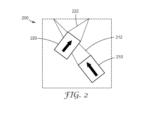
FIG. 2 is a top plan view of a lightguide including extractors with
directionally
dependent extraction efficiencies.
FIG. 3 is a top plan view of the lightguide of FIG. 2 receiving light from an
edge
location.
FIG. 4 is a top plan view of another lightguide including extractors with
directionally dependent extraction efficiencies.
FIG. 5 is a top plan view of the lightguide of FIG. 4 receiving light from two
edge
locations.
FIG. 6 is a top plan view of a lightguide including clusters of extractors
with
directionally dependent extraction efficiencies.
FIG. 7 is a top plan view of another lightguide including clusters of
extractors with
directionally dependent extraction efficiencies.
-5 -
3M 1934362v1
CA 02935238 2016-06-27
WO 2015/103188
PCT/US2014/072649
FIG. 8 is a top plan view of a lightguide including extractors with
directionally
dependent extraction efficiencies.
FIG. 9 is a top plan view of another lightguide including extractors with
directionally dependent extraction efficiencies.
Detailed Description
FIG. 1 is a top perspective view of a light extractor having directionally
dependent
extraction efficiency. Extractor 100 includes top face 110 and side face 120.
To provide an
example of directionally dependent extraction efficiency, first incident ray
130 and second
incident ray 140 are shown. An axis passing through extractor 100 is provided
for
illustrative purposes, providing a reference for the azimuthal orientation of
extractor 100.
The shape of extractor 100 may cause first incident ray 130 and second
incident
ray 140 to behave differently. Extractor 100, for example, if provided within
a lightguide
such that the index of refraction of or within extractor 100 is less than or
substantially less
than (e.g, in the case of air) the index of refraction of the lightguide, that
may cause first
incident ray 130, having a high incidence angle on top face 110, to be totally
internally
reflected off top face 110. Assuming extractor 100 is oriented or aligned such
that the
reference axis represents the thickness dimension of the lightguide, reflected
ray 132 may
be decoupled from being totally internally reflected or transported within the
lightguide
and exit the lightguide. In other words, reflected ray 132 is extracted. The
interaction of
incident light on the faces of extractor 100 may be modeled and predicted by
the extractor
shape and relative indices of refraction between extractor and lightguide. In
contrast,
second incident ray 140 is incident on side face 120 at a very low incidence
angle, in this
example near-normal incidence. Therefore, second incident ray 140 is
transmitted through
extractor 100. Transmitted ray 142, having no significant change in direction
within the
lightguide, may remain and continue to be transported within the lightguide.
In some
embodiments, second incident ray 140 may be reflected, nonetheless remaining
within the
lightguide, possibly incident on other extractors.
Extraction efficiency for an individual extractor may, at least for purposes
of this
application, be described as the ratio of light incident on an extractor to
light extracted by
-6-
3M 1934362v1
CA 02935238 2016-06-27
WO 2015/103188
PCT/US2014/072649
that extractor. Note that this characteristic is independent of size (at least
within
reasonable size scales) and dependent largely on shape. Total extraction
efficiency for an
individual extractor describes the ratio of light incident on an extractor
from any azimuthal
direction and incidence angle. It also may be useful to characterize a light
extractor¨in
particular an azimuthally asymmetric light extractor¨as having directionally
dependent
extraction efficiencies. For example, the extractor in FIG. 1 may have a first
extraction
efficiency for light incident along the azimuthal direction of first incident
ray 130, while
having a second, substantially less extraction efficiency for light incident
along the
azimuthal direction of second incident ray 140. From another perspective,
light may be
extracted at different efficiencies depending on the input face of the
extractor on which it
is incident. First incident ray 130 and second incident ray 140 are
substantially orthogonal
and represent cases with significant differences in extraction efficiencies.
In many
embodiments, extraction efficiencies may instead vary smoothly or continuously
as a
function of azimuthal incidence direction from a lower extraction efficiency
to a higher
extraction efficiency and vice versa. Extractor efficiency may also,
similarly, be a function
of polar angle of incidence. In some cases, it may be useful to characterize
useful
extracted light as being extracted light within a certain angle from the
normal or viewing
direction (reference axis in FIG. 1), such as 20 degrees.
Extractor 100 is depicted as a wedge in FIG. 1, but may instead be many
suitable
shapes. For example, the shape of the faces, such as top face 110 may be
designed or
configured to have a positive or negative cylindrical sag. Light may be
extracted within a
range of extraction angles or viewing directions. Changing the shape of the
faces of
extractor 100, in particular preferentially extracting faces such as, in the
configuration of
FIG. 1, top face 110, may shift, widen, narrow, or even split the range of
viewing angles
from light extracted by extractor 100. In some embodiments, extractor 100 may
be
designed to preferentially extract light within a range of viewing angles,
such as a 20
degree solid angle from the normal. Extractor 100 may be shorter, thinner,
wider, or
longer than the exemplary extractor shown in FIG. 1. Extractor 100 may have a
face that is
multifaceted, curved, concave, convex, spherical, aspherical, or any
combination thereof
Extractor 100 may have one or more truncated features or faces. Truncation may
occur
along either a horizontal plane, a vertical plane, or some other plane. In
some cases,
truncation along a horizontal plane may affect total extraction efficiency,
while truncation
-7-
3M 1934362v1
CA 02935238 2016-06-27
WO 2015/103188
PCT/US2014/072649
along a vertical plane may affect aziumuthal or direction dependent extraction
efficiency.
Exemplary shapes include wedges, wedges with positive or negative cylindrical
sag,
concave-concave wedges (concave surfaces as both top and side faces, concave-
convex
wedges (concave surface as one and convex surface as the other of top and side
faces),
aspheres, trimmed or truncated aspheres or sections thereof, and the like.
In some embodiments, as in FIG. 1, extractor 100 may have one input face from
which light is extracted with a higher efficiency. In other embodiments,
extractor 100 may
have a plurality of input faces from which light is extracted with a higher
efficiency. In
some embodiments, the term face may be inappropriate, because extractor 100
has a
smooth curved shape. Nonetheless, in these cases, segments or portions of
extractor 100
may have higher extraction efficiencies than other segments or portions of the
extractor.
For some extractors, it is appropriate to characterize them as preferentially
extracting light
along a range of optical paths. The range of optical paths may be
characterized by the
range of angles of incident light for which an extractor has a certain minimum
extraction
efficiency. This minimum efficiency may be 50%, 70%, 80%, 90%, 95%, or 99% of
incident light, depending on the application.
Extractor 100 may be any suitable size. Although extractor efficiency is
independent of the size of the extractor, the size of the extractor affects
the total intensity
of light extracted at that point. Further, design considerations such as
resolvability of
extractors by the human eye, speckle effects, and manufacturability may be
factors in
determining a desirable and suitable size or range of sizes for the
extractors.
FIG. 2 is a top plan view of a lightguide including extractors with
directionally
dependent extraction efficiencies. Lightguide 200 includes first extractor 210
preferentially extracting first range of optical paths 212, and second
extractor 220
preferentially extracting second range of optical paths 222. For the purposes
of this
application, or at least in terms of the figures within this application, the
convention of an
arrow indicating the extractor orientation by pointing toward the optical path
or incident
direction of greatest extraction efficiency is adopted. The range of optical
paths associated
with an extractor represents those paths that have an extraction efficiency
over a minimum
extraction efficiency. Depending on the particulars of the shape and design of
the
extractors, the range of associated optical paths need not be a continuous
range. Moreover,
the ranges of optical paths appear only two-dimensional because FIG. 2 is a
plan view,
-8-
3M 1934362v1
CA 02935238 2016-06-27
WO 2015/103188
PCT/US2014/072649
however, the range of optical paths may have any three-dimensional shape, also
controlled
by careful design of extractor shape.
Lightguide 200 is shown with dotted line edges to indicate that the specific
boundaries of the lightguide are not critical. Lightguide 200, however, may be
made from
any suitable material, including acrylic, polymeric materials, glass, and
others. In some
embodiments, lightguide 200 is formed from the same piece of material as the
extractors,
the extractors being an indentation or protrusion of the lightguide.
A replication tool may be used to fabricate the lightguides described herein.
The
replication tool, which may comprise metal, silicon, or other suitable
materials includes
the negative of the lightguide features including the protruded or recessed
light extractors.
The metal replication tool may be made from a master by electroplating or
electroforming
the metal, such as nickel, against the master and subsequently removing the
master. A
silicone replication tool can be made by curing a silicone resin against the
master and
subsequently removing the master.
The masters may be formed using a multi-photon (or, specifically, two-photon)
photolithographic process which is described in, for example, U.S. Patent No.
7,941,013
(Marttila et al.), which has been incorporated by reference herein. The multi-
photon
photolithographic process involves imagewise exposing at least a portion of a
photoreactive composition to light sufficient to cause simultaneous absorption
of at least
two photons, thereby inducing at least one acid- or radical-initiated chemical
reaction
where the composition is exposed to the light, the imagewise exposing being
carried out in
a pattern that is effective to define at least the surface of a plurality of
light extraction
structures.
First extractor 210 and second extractor 220 may be the same shape or they may
be
different shapes. Depending on the desired application, the extractors may be
similarly
sized or they may have different sizes. First extractor 210 preferentially
extracts light
propagating within the lightguide along first range of optical paths 212.
Correspondingly,
second extractor 220 preferentially extracts light propagating within the
lightguide along
second range of optical paths 222. In FIG. 2, second extractor 220 is disposed
on at least
an optical path of the first range of optical paths.
Thus, light propagating within lightguide 200 may be propagating along one of
the
optical paths in first range of optical paths 212 that is incident on second
extractor 220.
-9-
3M 1934362v1
CA 02935238 2016-06-27
WO 2015/103188
PCT/US2014/072649
However, because second extractor 220 is not oriented to preferentially
extract light
propagating within first range of optical paths 212, that light is extracted
with an
efficiency substantially less than light propagating within lightguide 200
that is incident
on first extractor 210. In other words, light propagating within first range
of optical paths
212 is extracted from second extractor 220 with an extraction efficiency that
is
substantially less than light propagating within first range of optical paths
212 extracted
from first extractor 210. In some embodiments, substantially no light along an
optical path
within first range of optical paths 212 may be extracted by second extractor
220, while
substantially all light along an optical path within first range of optical
paths 212 may be
extracted by first extractor 210.
FIG. 3 depicts the lightguide of FIG. 2 but with edges and a light source.
Lightguide 300 includes first extractor 310 preferentially extracting first
range of optical
paths 312 and second extractor 320 preferentially extracting second range of
optical paths
322. Light source 330 is positioned along an edge or at an edge location of
lightguide 300.
Light source generates ray 332, incident on both second extractor 320 and
first extractor
310. As in FIG. 2, second extractor 320 is disposed along at least one of
first range of
optical paths 312 associated with first extractor 310.
Light source 330 is meant to be a generic illumination location (or apparent
illumination location in the case of virtual images or reflected light) and is
provided for
better illustration of the general principles of lightguide 300. Light source
330, while
depicted as a circle, may have any dimensional extent and may be any suitable
light source
or set of light sources, including LEDs, CCFLs, or incandescent bulbs. In some
embodiments light source 330 may be or include a source of ambient light.
Light source
330 may emit or generate light in any wavelength or range of wavelengths.
Ray 332, generated by light source 330, is propagating within lightguide 300
along
one of first range of optical paths 312. Second extractor 320 is disposed
along that path,
and ray 332 is incident on a non-preferentially extracting face of second
extractor 320 and
is not propagating along one of second range of optical paths 322. Therefore,
second
extractor 320 extracts, if at all, ray 332 with a low extraction efficiency.
In some cases, ray
332 is transmitted through second extractor 320 without significant deviation.
In some
embodiments, ray 332 may be 90% transmitted and 10% extracted, and different
designs
-10-
3M 1934362v1
CA 02935238 2016-06-27
WO 2015/103188
PCT/US2014/072649
for the extractor shapes, particularly on the non-preferentially extracting
face or faces, will
provide different proportions. Ray 332 is then incident on first extractor
310, more
specifically on a preferentially extracting face of first extractor 310, and
may be extracted
with a high extraction efficiency, or at least in some cases substantially
higher than the
extraction efficiency of second extractor 320 for the same ray or optical path
from light
source 330.
FIG. 4 is a top plan view of another lightguide including extractors with
directionally dependent extraction efficiencies. Lightguide 400 includes first
extractor 410
associated with first range of optical paths 412 and second extractor 420
associated with
second range of optical paths 422. In the configuration of FIG. 4, each
optical path in first
range of optical paths 412 and second range of optical paths 420 intersect.
FIG. 5 is a top plan view of the lightguide depicted in FIG. 4, with the
addition of
edges and light sources to facilitate understanding of the general functioning
principles of
the lightguide. Lightguide 500 includes first extractor 510 and second
extractor 520,
associated as in FIG. 4 with first range of optical paths 512 and second range
of optical
paths 522, respectively. Disposed along or proximate edges of lightguide 500
are first light
source 530 and second light source 540. As in FIG. 3, the shapes and precise
location of
the light sources were selected for ease of illustration and should be
understood to provide
merely exemplary edge locations.
First light source 530 at a first edge location generates both first light ray
532 and
second light ray 534. First light ray 532 propagates along one of first range
of optical
paths 512, while second light ray 534 is not propagating along either first
range of optical
paths 512 or second range of optical paths 522. First light ray 532 is
incident on first
extractor 510 and is extracted with a certain first extraction efficiency.
Second light ray
534 is incident on second extractor 520 and is extracted with an extraction
efficiency
substantially less than the first extraction efficiency.
Similarly, second light source 540 at a second edge location generates both
third
light ray 542 and fourth light ray 544. Third light ray propagates along one
of second
range of optical paths 522 while fourth light ray 544 is not propagating along
either first
range of optical paths 512 or second range of optical paths 522. Third light
ray 542 is
incident on second light extractor 520 and is extracted with a certain second
extraction
-11 -
3M 1934362v1
CA 02935238 2016-06-27
WO 2015/103188
PCT/US2014/072649
efficiency. Fourth light ray 544 is incident on first extractor 510 and is
extracted with an
extraction efficiency substantially less than the second extraction
efficiency.
The concept depicted in the configuration of FIG. 5 may in some embodiments be
utilized to selectively illuminate certain portions of lightguide 500. For
example, if light
comes from first light source 530 but not second light source 540 (e.g., first
light source
530 is powered but second light source 540 is not), then the comparatively
higher
extraction efficiency of first extractor 510 vis-à-vis first light source 530
results in that
extractor extracting more light than second extractor 520. Correspondingly,
light coming
from second light source 540 but not first light source 530 results in second
extractor 520
extracting more light than first extractor 510.
FIG. 6 is a top plan view of a lightguide including clusters of extractors
with
directionally dependent extraction efficiencies. Lightguide 600 includes first
cluster 620,
second cluster 630, first light source 640, second light source 650, and third
light source
660. The light sources are placed to represent hypothetical edge locations for
ease of
explanation. FIG. 6 adopts the conventions of the previous figures for
indicating the
preferential direction of the light extractors within the clusters; however,
for the ease of
illustration the ranges of optical paths associated with each extractor is not
shown.
First cluster 620 and second cluster 630 may have the same or similar number
of
light extractors or they might each have different numbers of light
extractors. In some
embodiments, the size or shape of extractors within first cluster 620 and
second cluster
630 may vary to compensate for their position within lightguide 600; in some
cases, this
variation may help the uniformity of the extracted light. First cluster 620
and second
cluster 630 will have a minimum of a plurality of light extractors, but may
have any
suitable number of light extractors. In some embodiments, each light extractor
within a
cluster of light extractors may have a different orientation. In some
embodiments, several
light extractors within each cluster of light extractors may have the same
orientation.
Because of the complicated optical interaction between the clusters in
lightguide
600 and the light sources disposed in exemplary edge locations, explanatory
light rays are
not provided to illustrate the optical path between these sources and each
individual light
extractor or each cluster. In some embodiments, however, no optical paths in
the
respective associated ranges of optical paths for each extractor in a cluster
intersect one
another. In some embodiments, no optical paths in the respective associate
ranges of
-12-
3M 1934362v1
CA 02935238 2016-06-27
WO 2015/103188
PCT/US2014/072649
optical paths for each of two extractors in a cluster intersect one another.
First light
source 640, second light source 650, and third light source 660 may be
selectively driven
or powered to create interesting optical effects. For example, if first light
source 640 is
driven or powered, generating light incident on the clusters of light
extractors depicted
within lightguide 600, the three extractors within a cluster may extract the
light with
different extraction efficiencies. Similarly, if first light source 640 and
second light source
650 are made to generate light, light from those two light sources may appear
to be
combined to a viewer where clusters having extractors preferentially extract
light
propagating in the lightguide from the edge locations of each of first light
source 640 and
second light source 650. Alternatively, no light from one, the other, or
neither of first light
source 640 and second light source 650 may appear where clusters lack one or
both of the
light extractors oriented to preferentially extract light from those
directions.
This configuration¨combined with, in some embodiments, a third light source
660 (or more) and careful extractor design and arrangement on lightguide
600¨may result
in tremendous design flexibility in displaying information. For example, the
light sources
may be selectively or sequentially driven, with each orientation of light
extractor being
distributed differently within the lightguide. A different overall extraction
pattern is
different for each edge location of the light source. For example,
particularly in cases
where all light sources emit the same or similar color light, selective
illumination of each
of the light sources may provide different effects. For example, the extractor
clusters may
extract a lot of light, less light, or very little light, depending on the
distribution of
extractor orientations across the clusters and the edge location of the light
source. In
effect, the selective driving of the light sources may act as a dimmer for
otherwise
undimmable light sources. Two or more light sources may be driven
simultaneously as
well, giving even more control over various brightness levels. If the light
sources are
different colors or have different wavelength ranges, the light sources can be
separately
driven to provide the appearance of different colors resulting from the
controlled and
predictable combination of light from the light sources at the clusters. In
some
embodiments, the distribution of the extractor orientation across the clusters
may be such
that the powering of a light source will make an image, indicium, logo, or
security,
verification, or authentication feature appear, which would otherwise be
invisible or
substantially invisible under illumination from other edge locations. Each
orientation of
-13 -
3M 1934362v1
CA 02935238 2016-06-27
WO 2015/103188
PCT/US2014/072649
extractor may be distributed through the clusters to make an animation as the
light sources
are cycled. Timers, microprocessors, or other input devices may be used to
control the
illumination of the light sources. In some embodiments, the illumination of
the light
sources and hence the appearance of a particularly imagewise extractor pattern
may be
programmable, switchable, or otherwise controllable through user input.
FIG. 7 is a plan view of another lightguide including clusters of extractors
with
directionally dependent extraction efficiencies. Lightguide 700, similar to
lightguide 600
in FIG. 6, has clusters of similarly oriented light extractors as first
indicium 710 and
second indicium 720. Also positioned at an edge location are first light
source 740 and
second light source 750. First light source 740 generates first light ray 742
and second
light ray 744. Second light source 750 generates third light ray 752.
The dashed lines in lightguide 700, besides the dashed lines for the
lightguide to
deemphasize the specific dimensions of lightguide 700, represent the
approximate
boundaries of the indicium, which are simplified for the ease of illustration.
Any shape or
size is possible with an arrangement of similarly oriented light extractors,
such as any
suitable logo, shape, word, or other indicium. The operation of lightguide 700
is similar to
lightguide 600 of FIG. 6, with light being extracted differently based on the
orientation of
the directionally dependent light extractors and the edge location of the
light source. For
example, first indicium 710 receives light from first light source 740 as
second ray 744
and from second light source 750 as third ray 752. The extractors of first
indicium 710 are
oriented, however, to preferentially extract light along optical paths from
first light source
740, while extracting light along optical paths from second light source 750
at a
substantially lower efficiency. Therefore, for example, if first light source
740 emitted
blue light and second light source 750 emitted red light, and the two were
emitting light
simultaneously, first indicium 710 would extract the blue light at a much
higher efficiency
than the red light. Therefore, that portion of lightguide 700 corresponding to
first indicium
710 would appear blue.
Similarly, second indicium 720 receives light from both first light source 740
as
first ray 742 and from second light source 750 as third ray 752 (at least,
that portion of
third ray 752 that is not redirected or extracted by the extractors of first
indicium 710).
However, the extractors of second indicium 720 are configured to extract light
along
-14-
3M 1934362v1
CA 02935238 2016-06-27
WO 2015/103188
PCT/US2014/072649
optical paths from second light source 750 at a much higher efficiency than
light along
optical paths from first light source 740. Thus, when the hypothetical
described for first
indicium 710 is applied to second indicium 720¨that is, first light source 740
emits blue
light and second light source 750 emits red light, second indicium 720 would
appear red.
Note that in some embodiments, because of the directionally dependent
extraction
properties of the extractors of lightguide 700, if the light sources were
driven
simultaneously, first indicium 710 may appear blue while second indicium 720
may
appear red, with very little cross-talk or color mixing. Similarly, one or the
other indicium
may be illuminated with the other feature remaining substantially invisible.
In some
embodiments, an overall indicium on the lightguide is composed of non-
overlapping
segments, such as first indicium 710 and second indicium 720. There may be a
one-to-one
correspondence between the non-overlapping segments and the clusters of
extractors, as
substantially shown in FIG. 7.
FIG. 8 is a top plan view of a lightguide including extractors with
directionally
dependent extraction efficiencies. Lightguide 800 includes a variety of light
extractors,
which are not individually labeled or identified in this figure. Further,
first light source
810, second light source, 820, and third light source 830 are disposed at
different edge
locations. As for FIGS. 6-7, light from each light source edge location may
illuminate a
different subset of light extractors in lightguide 800. In this way,
lightguide 800 may be
configured such that different images, logos, or extractor patterns are
visible depending on
which edge location light from the light sources originates. Because
extraction efficiency
is not necessarily binary (all light being extracted or all light being
transmitted or reflected
within the lightguide), an extractor may be oriented to extract light at an
intermediate
efficiency from two or more edge locations.
FIG. 9 is a top plan view of another lightguide including extractors with
directionally dependent extraction efficiencies. Lightguide 900 includes a
plurality of
extractors which are not individually labeled or identified. First light
source 910 and
second light source 920 are disposed at different edge locations. Similar to
FIGS. 6-8,
light from each light source edge location may illuminate a different subset
of light
extractors in lightguide 900. FIG. 9 depicts a superimposed pattern. For
example, light
from first light source 910 may provide substantially uniform illumination
over the
depicted portion of lightguide 900. Alternatively or in addition, light from
second light
-15-
3M 1934362v1
CA 02935238 2016-06-27
WO 2015/103188
PCT/US2014/072649
source 920 may provide illumination only in the subset depicted with its light
extractors
oriented to preferentially extract light from the edge location of second
light source 920.
In a sense, light from first light source 910 forms a first image at the
emission surface of
lightguide 900 while light from second light source 920 forms a second image
at the
emission surface of the lightguide. Applications for this configuration
include, for
example, in the case of an automotive taillight, turn signals superimposed on
running
lights, which can be run simultaneously or separately and with different
intensities and
patterns. Other applications¨for example, signage, general or decorating
illumination
including lamps and luminaires, transparent lighting such as sunroofs,
windows, and
skylights that can be selectively illuminated¨are contemplated and may include
the
lightguides and configurations described herein. Further, such applications
may
alternatively or additionally include elements described in conjunction with
other figures,
for example, those described in FIGS. 6-8.
Descriptions for elements in figures should be understood to apply equally to
corresponding elements in other figures, unless indicated otherwise. The
present invention
should not be considered limited to the particular embodiments described
above, as such
embodiments are described in detail in order to facilitate explanation of
various aspects of
the invention. Rather, the present invention should be understood to cover all
aspects of
the invention, including various modifications, equivalent processes, and
alternative
devices falling within the scope of the invention as defined by the appended
claims and
their equivalents.
-16-
3M 1934362v1