Note: Descriptions are shown in the official language in which they were submitted.
CA 02935318 2016-06-28
WO 2015/102524 PCT/SE2m4itioni60
1
TITL.E: INSERT FOR AN ORGAN TRANSPORT DEVICE
FIELD OF INVENTION
The present invention relates to an device for maintaining an organ, such as a
heart,
viable and transportable for a long time, such as up to and exceeding 24
hours. In more detail,
the invention relates to an insert for use in an organ transport device for
transporting and
storing of the organ before a transplant thereof.
BACKGROIJND OF THE INVENTION
Us Patent No. 7176015 discloses a transportable organ preservation system for
maintaining an organ viable for successful implantation into a human
recipient. The system
comprises a cylinder that contains 255 litre of oxygen sufficient for up to 34
hours of
1 5 perfusion time. The organ is immersed in a pertlision fluid, which is
oxygenated and pumped
through the coronary vessels of the heart via the aorta of the heart in a
retrograde flow. The
system containing the heart, the oxygen cylinder. the pump assembly and hoses
are all
arranged in a tray, which is inserted in a commercial cooler device having
cooling blocks and
an insulation for maintaining the cylinder and the heart at a temperature of
about 4 C. The
sterility is maintained by a lid, which closes the cylinder.
The patent publication WO 2011/037511 Al discloses a method and a device for
treatment of a heart after harvesting and before transplantation, in which a
perfusion fluid is
circulated through the coronary blood vessels of the heart. The perfusion
fluid is cardioplegic
and comprises an oncotic agent exerting an oncotic pressure larger than about
30 intnHg and
the perfusion is performed at a pressure which is at least 15 mmHg and at
least 15 mmHg
lower than said oncotic pressure. The perfusion may be intemittent. WO
2011/037511 Al is
assigned to the assignee of the present application and its technical contents
are included in
the present application by reference.
The patent publication WO 2012/128696 Al discloses an apparatus for enclosing
an
organ after harvesting and before implantation, comprising: a vessel enclosing
a fluid; a
connection tube for connecting a fluid flow hose to the organ for passing a
fluid to the man
by means of a pump. A degassing hose extending from the connection tube from a
position
adjacent the connection of the tube with an inlet part of the organ and to
said vessel. A pinch
valve is arranged in the degassing hose. During a degassing phase, the pinch
valve is opened
to allow fluid flow from the pump, via the fluid flow hose to the connection
tube and via the
degassing hose to the vessel for expelling air entrapped in the fluid flow
system. A balloon is
arranged to prevent fluid flow via the connection tube to the organ during the
degassing phase.
CA 02935318 2016-06-28
WO 2015/102524 PCIISE2914/009160
A sterility arrangement closes the vessel at the top thereof and may be
replaced by a second,
third etc. sterility arrangement without compromising the sterility. WO
2012/128696 Al is
assigned to the assignee of the present application and its technical contents
are included in.
the present application hy reference.
There is a need in the art for an insert, which may facilitate the arrangement
of the
organ in a correct position in the organ transport system, which insert may be
sterlized and be
disposible.
SUMMARY OF THE INVENTION
Accordingly, an object of the present invention is to mitigate, alleviate or
eliminate
one or more of .the above-identified deficiencies and disadvantages singly or
in any
combination.
According to a first aspect, there is provided a device for arranging a
harvested organ
to be stored in an enclosure before transplantation, whereby the organ is
connected to a tube
for supply of a medical fluid to the organ, comprising: a substantially
cylindrical insert
intended to he arranged in the enclosure For the organ; and a fixture for
immobilizing the tube
in a central position of the insert.
According to an embodiment, the fixture may comprise an arm extending from the
periphery of the fixture to the center of the fixture; and a jaw device at the
arm for gripping
the tube and maintaining the tube in a predetermined height position. In
addition, there may be
arranged a locking jaw for co-operation with the jaw device for locking the
tube against
unintentional withdrawal from the jaw device.
According to another embodiment, the device may further comprise two ears
arranged at the fixture for co-operation with openings arranged in the insert
for maintaining
the fixture in a predetermined position in relation to the insert.
According to a further embodiment, the device may further comprise a lid
arranged
above the 'fixture for locking the fixture in position and for closing the
space belovv the fixture.
The organ may be a heart and the tube may be attached to an aorta residue of
the .heart.
BRIEF DESCRIPTION OF THE DRAWINGS
Further objects, features and advantages of the .invention will become
apparent from
the following detailed description of embodiments of the invention with
.reference to the
drawings, in which:
Fig. 1 is a schematic cross-sectional view of a prior art device for storage
and
transportation of an organ.
Fig. 2 is a schematic perspective view partially in cross-section of an
embodiment of
the device according to the invention.
CA 02935318 2016-06-28
WO 2(115/11.12524 PCT/SE2014/000160
3
Fig. 3 is a perspective view of an insert in the embodiment shown in Fig. 2.
Fig. 4 is a perspective view of a fixture in the embodiment shown in Fig. 2.
Fig. 5 is an exploded plan view of the fixture of Fig. 4.
Fig. 6 is a plan view of the fixture according to Fig. 4 in a locked position.
Fig. 7 is a plan view of a lid in the embodiment shown in Fig. 2.
Fig. 8 is a perspective view of the insert a.n.d fixture of the embodiment of
Fig. 2 and
shows the insert and fixture in an initial position for gripping a tube with
an organ hanging in
the tube.
Fig. 9 is a perspective view similar to Fig. 8 with the fixture in a second
position.
Fig. 10 is perspective view similar to Fig. 8 with the fixture in a third
position.
Fig. 11 is perspective view similar to Fig. 8 with the fixture in place and a
lid being
arranged for closing the space.
Fig. 12 is a perspective view similar to Fig. 11 with the lid in a second
position.
Fig. 13 is a perspective view similar to Fig. 11 with the lid in a final
locked position.
Fig. 14 is an exploded perspective view of an alternative embodiment attic
device
according to the invention.
Fig. 15 is a plan view of the embodiment shown in Fig. 14.
Fig. 16 is a partially cut perspective view of the embodiment shown in Fig. 14
in an
assembled state.
Fig. 17 is a perspective view of the fixture in the embodiment shown in Fig.
14.
Fig. 18 is a perspective view from below of the embodiment shown in Fig. 14
and
showing a support plate.
Fig. 19 is a plan view of the support plate according to Fig. 18.
Figs. 20, 21 and 22 are plan views showing a lid to the fixture of the
embodiment
according to Figs. 14 and 17.
DETAILED DESCRIPTION OF EMBODIMENTS
Below, several embodiments of the invention will be described. These
embodiments
are described in illustrating purpose in order to enable a skilled person to
carry out the
invention and to disclose the best mode. However, such embodiinents do not
limit the scope of
the invention. Moreover, other combinations of the different features are
possible within the
scope of the invention..
The below embodiments disclose apparatuses and methods for handling an organ
between (and including) harvesting the organ in a donor and up to and
including implant of
the organ in a recipient. While the embodiments are described in connection
with a heart to be
transplanted, th.e same device may be used for other organs, such as lungs,
liver and kidney.
CA 02935318 2016-06-28
WO 2(115/102524 PCT/SE2014/000160
4
Most organs cannot withstand a long ischemic time, i.e. a condition without
supply of
nutrients and oxygen, which are normally supplied via the blood. For example,
at normal
temperature of 37 C, a heart cannot withstand more than about 20 minutes.
while other
organs, such as the lungs can withstand up to 40 minutes or more.
The outcome of an organ transplantation is among others dependent on the
condition
of the organ before harvesting. All efforts should be undertaken to maintain
the donor and its
organs in as good a condition as possible before harvesting. Such efforts may
for example
include the method steps and processes disclosed in the patent publication
WO 2010/077200 Al, the contents of which are included in its entirety in the
present
specification by reference. Generally, the methods of this publication
involves that the
potential donor is treated as vigorously as possible before death, and that
circulation and
ventilation are maintained after the time the potential donor is declared
brain dead, in order to
avoid ischemic conditions. After obtaining consent from the potential donor in
advance and/or
his/her next of kin, the potential donor is treated according to a strategy
that maintains the
organs in a viable condition, after brain death is declared.
Next, the organs are harvested, most often within 24 hours after declaration
of brain
death. in some countries, brain death is not defined or authorized as
indication of actual deatlì..
in such countries, the above-mentioned expression "declaration of brain-death"
is intended to
encompass any other definition of death or actual death, used in such country.
For the purpose
of the embodiments, brain death involves that the brain and the brain stem do
no longer send
any ele,ctrie stimulation signals to the nerve terminals.
The organs are examined for viability and stored, nonnally under hypothermic
conditions until transplantation.
Finally. the organs are implanted in the recipient.
All steps are important .fbr t.he final result of the organ transplantation.
The present embodiments generally deal with the procedure between harvesting
and
implantation of an organ, especially of a heart.
In a presently used procedure, the harvesting of a heart may start with
exposing the
heart to a cardioplegic and cold saline fluid, which is infused in the heart.
The heart stops
beating and the circulation stops. The heart may now be in the risk for an
ischemic condition,
since there is no blood flow. However, the infused tluid may provide
sufficient oxygen and
nutrients for avoiding ischemic conditions. The heart is made free from the
donor and the
aorta is cut and maintained with a sufficient length, called the aorta
residue.
The heart may be examined for viability, involving, for example, checking for
aortic
valve insufficiency and other examinations. Aortic valve insufficiency may be
examined by
adding a fluid to the aorta and examine whether the fluid level decreases.
Since the fluid has
no other escape way except via the aortic valve, this is a good test of the
patency of the aortic
CA 02935318 2016-06-28
WO 2015/102524 PCT/SE2014/011016(1
valves. It is mentioned that the fluid may escape via the coronary vessels.
However, the
pressure for passing fluid through the coronary vessels is normally higher
than a few
centimeter of water pillar, which means that substantially no flow will pass
through the
coronary vessels during such an aorta valve test. The heart may also be
examined by
5 angiographic methods in order to detect defects in the coronary vessels
and other problems.
A connector tube is attached to the aorta and the heart is moved to a
preservation
apparatus and connected in a preservation circuit, for example as described in
the above-
mentioned US Patent No. 7176015 or the patent publication WO 2010/077200 Al. A
preservation solution may be circulated through the coronary vessels via the
aorta. The
preservation is nomially cold in order to cool the heart and maintain the
heart in a
hypothermic condition. Other strategies may as well be used.
Fig. 1 discloses a device as shown in the prior art patent publication
WO 2012/128696 Al comprising a vessel enclosing a heart to be transplanted.
The heart is
immersed in a preservation solution. The heart is shown schematically with the
a ventricle to
the right in the figure and includes an aorta, ending in an aortic valve,
which opens into a left
ventricle of the heart. A mitral valve connects the ventricle with a left
atrium.
During normal operation in the living human body, blood enters the left
portion of
the heart via four pulmonary veins, one of which is shown in Fig. I. The blood
fills the left
atrium and the left ventricle during diastole, while the initral valve is open
and the aortic valve
is closed. During contraction, the left atrium is first contracted forcing
further blood into the
left ventdele. Then, the left ventricle is contracted, whereupon the mitral
valve is closed and
the aortic valve is opened and the blood is forced out into the body via the
aorta.
The right portion of the heart operates in a similar way, while blood enters
the right
atrium via two veins. superior vena cava and inferior vena cava. During
diastole, blood fills
the right atrium and right ventricle via tricuspid valve. During contraction
of the heart, the
blood in the right ventricle is forced to the lungs via pulmonary valve and
pulmonary artery.
The heart muscle is provided with blood supply via a left coronary artery and
a right
coronary artery. each dividing into capillaries. The coronary blood is
returned to the right
atrium via coronary sinus, which collects blood from several coronary veins,
such as middle
cardiac vein and great cardiac vein. The coronary sinus opens into the right
atrium via
Thebesian valve (not shown), which prevents backtlow into the coronary sinus.
During harvesting of the heart, the heart may be paralyzed via infusion of a
cardioplegic fluid into the coronary circulation of the heart. The
cardioplegic fluid is normally
cold to induce a hypothermic condition in the heart. The aorta is cut in a
position to keep it
with a sufficient length so that a tube may be attached to the aorta for
antcgrade supply of
coronary fluid flow.
CA 02935318 2016-06-28
WO 2015/102524 PCT/SE2014/000160
6
In Fig. 1, the heart 1 is shown removed from the donor and with a connection
member such as a connection tube arranged in the aorta. The heart I is
immersed in the vessel
2 so that the entire aorta is immersed below a fluid surface, in order to keep
the aorta moist.
There is only one connection required during the harvesting of the organ,
namely between the
connection tube and the aorta, which connection can be made relatively
quickly.
The connection tube is inserted in the aorta so that the end of the connection
tube is
above the aortic valve and the openings of the coronary arteries. The coronary
arteries open
normally between 5 and 10 mm above the aortic valve. Since the aortic valve is
closed, all
fluid passing through the connection tube flows through the coronary arteries.
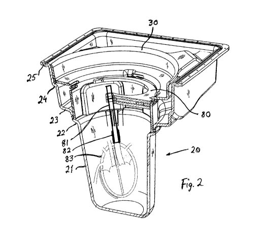
Fig. 2 discloses a modified enclosure for the organ according to an embodiment
of
the present invention.
The enclosure 20 comprises a lower portion 21, a first shoulder 22, a second
shoulder
23 and a third shoulder 24. The third shoulder 24 is connected to a
substantially rectangular
rim 25. The enclosure 20 fits in a box of the type disclosed in WO 2012/128696
Al. The box
comprises pumps, cooling devices, oxygenator. tubes, valves etc for
circulating a fluid.
Inside said enclosure 20. there is arranged an insert 30 according to an
embodiment
of the invention. The insert 30 rests on said first shoulder 22. The insert 30
is provided with
legs, one of which is visible in Fig. 2. There are four legs each arranged in
a corner inside said
rectangular rim 25 and along the side in order to. immobilize said insert 30.
Thus, the insert is
easily inserted into the enclosure 20 from above.
The insert 30 aecomodates a fixture 80 for a connection tube 81. which is
connected
to the residue of the aorta 82 of the heart 83.
The insert 30 is shown separately in perspective in Fig. 3.
The bottom portion ofthe insert 30 is formed of a lower cylindrical portion
35.
having a bottom rim 36, which is arranged to rest on shoulder 22 or being
arranged just above
shoulder 22. The lower cylindrical portion 35 is provided with four recesses
37 leaving an area
for any fluid to pass from the space outside the insert 30 to the space below
the insert 30.
An annular portion 38 is at its inner side connected to the lower cylindrical
portion 35
and an upper cylindrical portion 39 is connected to the outside of the annular
portion 38. The
upper cylindrical portion 39 is supported by said four legs 31. 32, 33, 34.
The upper portion of each recess 37 forms a shoulder 40. Directly above each
recess
37, there is arranged an opening 41 having a substantially rectangular shape.
Offset about 45
in relation to said openings 41, there is a set of lbur slits 43, each having
a side entrance 44 via
a recess 45.
Fig. 4 is a perspective view of a fixture 80 and Fig. 5 is an exploded plan
view of the
fixture 80. As clearly appears from Fig. 5, the fixture comprises four
separate parts 83. 84. 85,
86, which are joined to each other by three screws or rivets or similar means
arranged in three
CA 02935318 2016-06-28
WO 2015/102524 PCT/S.E2014/000160
7
holes 87, 88, 89. The first- upper part 83 of the fixture is annular over an
arch of three quarter
nf a circle and has a dimension so that it may be arranged inside the insert
30 as shown in Fig.
2 and resting on the shoulders 40 of each recess 37. The upper part 83
comprises two ears 90
and 91 arranged at a mutual distance of 270' along the periphery of the upper
part 83. The
ears 90 and 91 are dimensioned and arranged for fitting in two of the
rectangular openings 41
while the rest of the fixture 80 rests on the shoulders 40.
In the centrum of the fixture, there is arranged a support jaw 92 at the end
of an ann
93 extending from the central portion of the first part 83. The support. jaw
92 is dimen.sioned
to enclose and retain a tube 81 as will be explained in more detail below. The
jaw 92 extends
over slightly more than 180 to grip the tube 81 with a friction grip. By this
arrangement, the
tube gripped by the support jaw 92 will be positioned in the middle of' the
enclosure 20. A
second part 84 is arranged below the arm 93 with a distance and has the sanie
shape as the arm
93 and comprises a support jaw 94. A third part 85 and a fourth part 86 are
arranged between
the arm 93 and the second part 84. The .fourth part 86 has a locking jaw 94
similar to the
support jaws 92 and 94 but facing in the opposite direction.
The fourth part 86 is pivotible between an open position as shown in Fig. 4 to
a
closed position shown in Fig. 6. In the closed position, the fourth part 86 is
locked by the third
part 85 by a hook system 96, 97. The hook system may be released by a lever
98.
Finally, Fig. 7 shows a lid 101 to be arranged above support fixture 80.
Figs. 8 to 13 explain the use of the described insert.
In Fig. 8, the insert 30 is arranged in an enclosure (not shown) .in the
manner shown
in Fig. 2. The residue of the aorta 82 of the heart has been connected to a
tube 81.
The tube 81 is inserted in the support jaws 92 and 94 of the fixture 80 as
shown in
Fig. 8. The height position of the heart is adjusted as desired by moving the
tube 81 in the
height direction as seen in Fig. 8. Normally, it is desired that the heart
hangs in the tube 81
slightly above the bottom of the enclosure 20, but the user has full control
of the height
position and may choose another height position.
When the desired position has been obtained, the locking jaw 95 is pivoted to
a
locked position shown in Fig. 9. The hook system 96 and 97 locks the fourth
part 86 in the
locked position.
Fig. 10 shows the fixture 80 after being lowered and arranged in the insert
30. The
ears 90 and 91 of the -fixture 80 are arranged in the rectangular openings 41
while the rest of
the fixture rests on the shoulders 40. 11 it is desired to adjust the position
of the heart, this can
be done by activating the lever 98, thereby releasing the locking jaw 95,
whereupon the
height position of the tube 81 and the heart can be adjusted up or down. Then,
the lever 98 is
moved to the locked position.
CA 02935318 2016-06-28
WO 2015/102524 PCT/SE2014/000160
8
It may be desired to arrange a lid 101 above the insert 30 as shown in Fig.
11. The lid
comprises a slit 102, arranged to pass the tube 81 from the periphery to the
center of the lid
101. Two grip holes 103 arc arranged for handling the lid by two fingers of
the user. In
addition. there are four tabs 104 arranged equidistantly along the periphery
of the lid. The lid
and the tabs 104 are arranged and dimensioned to fit in the four slits 43
arranged in the insert
30. The lid 101 is moved so that the tube 81 is arranged in the slit 102 and
the tabs 104 are
moved down the recesses 45 as shown in Fig. 12.
Finally, the lid 101 is pivoted clockwise as shown in Fig. 13 for moving the
tabs 104
via thc side entrances 44 into the slits 43, wherein the lid 101 is locked in
place and locks the
fixture so that it cannot be removed. In the final position, the slit 102 of
the lid is arranged
above the arm 93, so that no fluid may pass out through the slit 102.
The fixture 80 and the lid 101 may be arranged in four different positions
displaced
90 in relation to each other.
The fixture and lid are constructed so that they can be operated by one hand
of the
user, so that the user can use the other hand for manipulating the organ to a
desired position.
The tube 81 may be provided with a coupling (not shown) for connection to a
tube
system as shown in Fig. I. The tube 81 may be connected to the tube system
just below the
bifurcation of the tubes shown in Fig. 1. Other arrangements may be foreseen,
but such
arrangements are not the subject of the present invention.
The same system for circulating a fluid as disclosed in WO 2012/128696 Al may
be
used in the device according the present invention. However, another
circulation system may
be used, and such systems are not the subject of the present invention.
If two tubes are used as disclosed in WO 2012/128696 Al, such tubes may enter
the
insert 30 via two holes 46, 47 in the upper cylindrical portion 39 as shown in
Fig. 3.
The insert 30, the fixture 80 and the lid 101 may be disposable parts used
once and
then discarded. The parts should bc sterilized before use.
A swecond embodiment of the device according to the invention is shown in
Figs. 14
to 19. The second embodiment comprises an enclosure 120 similar to the
enclosure 20 and an
insert 130 similar to insert 30.
The enclosure 120 is provided with an upper rim 125, which is provided with a
plurality of holes 126. A rectangular plate 140 having the same plurality of
holes 141 is
attached to the enclosure 120 and is tightened to the enclosure by a plurality
of screws, not
shown. The rectangular plate is provided with a circular opening 142 having a
slightly smaller
dimension than the insert 130, Thus, the plate 140 locks the insert in place.
A circular rim or collar 150 may be inserted in the opening 142 for attaching
a sterile
cloth to the upper surface of the device.
CA 02935318 2016-06-28
WO 2015/102524 PCT/SE2014/1100160
9
Fig. 15 shows the second embodiment in an assembled condition, from above,
while
Fig. 16 is a broken perspective view, showing the enclosure 120, the insert
130 and the fixture
180.
Fig. 17 shows the fixture 180 according to the second embodiment. In contrast
to the
fixture 80. it does not have any moveable part, but the tube is kept in a
central recess 181 by a
friction grip. The fixture comprises four layers 182, 183, 184, 185, each
being provided with a
recess 186, 187, 188, 189. The recesses 187, 188 in the middle extend over
1800 or slightly
more, such as 185 , while the upper and lower recesses 189, 186 extend over a
larger bow,
such as 190 to 195 . Thus, a tube inserted in the recess is kept by friction
by all four recesses
and is stopped from passing out of the recesses mainly by the lower 186 and
upper 189
recesses.
Turning again to Hz. 16, there is shown a support plate 160, which support
plate is
also shown in Figs. 18 and 19. The support plate 160 comprises several holes
and openings
161 for supporting devices, such as oxygenators. filters and tube sets etc. A
circular opening
162 is arranged for fitting outside the bottom portion of the enclosure 120.
The inner periphey
of the opening 162 is provided with several chamfered peripheral portions 163,
which fit into
recesses 164 in the outer surface of the enclosure 120, see Fig. 16 and Fig.
18.
As further shown in Fig. 16. the support plate 160 may support a stand 196 for
supporting the fixture 180' in a raised position. The distance between the
raised fixture 180'
and the top surface of the enclosure is substantially the same as the depth of
the enclosure 120.
The heart may be attached to the fixture 180' in the raised position and the
height position be
adjusted to a desired position, whereupon the fixture 180' is moved down to
the final position
shown by the fixture 180 in Fig. 16.1n this manner, the distance between the
heart and the
bottotn surface of the enclosure 120 can be adjusted in advance. The stand 196
may be
attached to the support plate 160 as shown, or alternatively to the collar 150
shown in Fig. 14.
'Me stand 196 may be removed after use.
The raised position may be in relation to the top surface of the enclosure 120
as
defined by the plate 140. Alternatively. the lid 190 shown in Fig. 20 may be
put in place for
defining the raised distance corresponding to the bottom of the enclosure.
After the heart has
been arranged in a desired position with the fixture in the raised position
and with the lid in
place. the lid is removed and the fixture is moved to the final position and
the lid is again put
in place now above the fixture and the heart.
Fig. 20 shows a lid 190 similar to lid 101 shown in Fig. 11. However, lid 190
has a
wider slit 191. In addition, the lid has two grip holes 192, 193 and tbur tabs
194. Fig. 21
shows the lid arranged upon the fixture 180 in an initial position. Fig. 22
shows the lid rotated
so that a portion of the lid is positioned below a shoulder 195 of layer 185
of the fixture. In
this position, the lid locks the tube in place as desired.
CA 02935318 2016-06-28
WO 2015/102524 PCT/SE2 I 441119160
ln the claims, the term "comprises/comprising" does not exclude the presence
of
other elements or steps. Furthermore, although individually listed, a
plurality of means,
elements or method steps may be implemented by e.g. a single unit.
Additionally, although
individual features may be included in different claims or embodiments, these
may possibly
5 advantageously be combined, and the inclusion in different claims does
riot imply that a
combination of features is not feasible and/or advantageous. in addition,
singular references
do not exclude a plurality. The terms "a", "an", "first", "second" etc. do not
preclude a
plurality. Reference signs in the claims are provided merely as a clarifying
example and shall
not be construed as limiting the scope of the claims in any way.
10 Although the present invention has been described above with reference
to specific
embodiment and experiments, it is not intended to be limited to the specific
form set forth
herein. Rather, the invention is limited only by the accompanying claims and,
other
embodiments than those specified above are equally possible within the scope
of these
appended claims.