Note: Descriptions are shown in the official language in which they were submitted.
5
Description
Adhesive tape for flying splice
The invention relates to an adhesive tape for the on-the-fly roll changeover
of flat web
material wound up into rolls (splicing method, or simply "splice"), having an
adhesive
facing side and having a main carrier on whose reverse face an adhesive has
been
provided which in the splice process can be split off from the main carrier,
and also to a
splicing method for the on-the-fly roll changeover of flat web material wound
up into rolls,
for which an adhesive tape of this kind is suitable.
Roll changeover on the fly in paper mills or the like is a commonplace method
for
replacing an old, almost fully unwound flat web roll by a new roll without
having to stop
the high-speed machinery. It uses double-sided self-adhesive tapes, known as
tabs,
which on the one hand are highly adhesive and highly tacky, while on the other
hand do
not cause disruption in the paper machine, by virtue of their water-soluble
self-adhesives
and paper carriers, when the paper wastes are reused. These tabs are adhered
artfully in
sawtooth form at the web start, a procedure which requires experienced
personnel, with
the high-speed machinery leaving generally only little time for the entire
operation.
Although this technology is well-established and well-practised, it is not
without certain
disadvantages. Thus experienced staff are required, the procedure is
intrinsically hectic,
and the bonds are also relatively thick, since in each case two plies of paper
and the
adhesive tab in-between are the result: a result which is unwanted in the
paper industry,
since the high thickness may result in tearing, including at coating blades in
paper coating
machines.
For this butt splicing during on-the-fly roll changeover there are various
products on the
market, known as tabs, which in addition to a paper carrier are coated on both
sides with
Date Recue/Date Received 2022-05-03
CA 02935514 2016-07-08
2
a water-soluble self-adhesive. Adhesive tapes of this kind are on the market,
for instance,
under the name tesafix (tesa SE).
It has been possible to improve splice preparation and splice implementation
through the
use of specific adhesive tapes which on the one hand are suitable for
guaranteeing, for
the preparation, a roll end bond which does not unintentionally open again
even when the
rolls are being accelerated to their process speed, these specific adhesive
tapes
nevertheless having a flat predetermined breakage point such that the end bond
opens at
exactly the moment, or immediately thereafter, when the new roll is being
adhered to the
old, outgoing web by means of this very adhesive tape, so that the new flat
web is
integrated into the process together with the old, outgoing flat web to which
it is now
bonded, thereby ensuring the continuity of the process.
Adhesive tapes of this kind are, for instance, those which are equipped on the
reverse
face of their main carrier with multilayer splitting systems comprising a
splittable paper
carrier, these tapes being described for example in specifications DE 196 28
317 A and
DE 199 02 179A.
Flying splices of this kind are made in the production or processing of other
flat web
materials, such as films and the like, for example, and in some cases further-
adapted
adhesive tapes are used there.
As a result of the specific construction of such speciality adhesive tapes,
having a
plurality of functional layers, adhesive tapes of these kinds are relatively
thick. As a
consequence of this, the thickness of the bond site of the two webs to one
another is
relatively large; where otherwise a flat web is guided through the apparatus,
the
sequence in the region of the bond site is a sequence of at least two flat
webs with the
web-connecting adhesive tape arranged between them. The thickness of
commercial
adhesive tapes for continuous bonding, in the region of the splitting system
(i.e. the
predetermined breakage point), is customarily about 100 to 200 pm in the split
state.
Added to this are the paper thicknesses at the bond site, which may also be in
the range
of several 10s to several 100s of pm. This produces the substantial thickness
of the
paper web assembly in the splicing operation, since it is this point, in the
course of travel
in processing machinery, that makes first contact with coating assemblies,
printing rolls or
the like, and here the shape and thickness of the splice poses a particular
risk of tearing.
3
The aim is therefore to use extremely thin adhesive splicing tapes. One
solution for an
adhesive tape of this kind is proposed in DE 102 10 192 A, where an adhesive
tape is
used that comprises a main paper carrier, an adhesive on the facing side, and
a thin
stripe of adhesive (instead of a multilayer splitting system) on the reverse.
Splitting during
the splicing operation in this case is realised by the main carrier being
splittable at least in
the region of the underlying stripe of adhesive, and by a corresponding
portion of the
paper being torn out from the main carrier during splicing.
Also part of the prior art is an adhesive tape wherein a paper carrier is
coated on both
sides with a water-soluble self-adhesive and where the paper carrier consists
of an
areally splittable paper. This adhesive tape is described in DE 196 32 689 Al.
A paper
carrier is disclosed which splits in full width. With this mode of
functioning, there is a
dramatic reduction in the maximum tensile force of the split paper and hence
in the
maximum possible web tension to be transmitted. In the case of centrally split
papers, it is
reduced by at least 50%. Where the splitting plane is not central, the maximum
tensile
force may even be reduced by well below 50%.
A feature shared by both aforementioned solutions is that the splitting of
paper carriers
produces surfaces which are not very smooth and which, moreover, possess a
fibrous-
frayed structure. Fibrous and frayed structures of this kind are a
disadvantage during
coating or in the print works, for example, since fibres may be deposited in
the printing
mechanism and lead ultimately to incorrect printing, and/or even at the
coating unit in the
paper mill, there may be deposits beneath the coating assembly. A possible
consequence of such deposits is that the coating is irregular and faulty,
producing a
coating profile that is not clean and uniform. This leads to quality
detractions in the
product.
It is an object of the invention to provide an adhesive tape for flying splice
that produces
as small as possible a thickness in the region of the bond between the old and
new webs,
while nevertheless retaining the full maximum tensile force to accommodate the
maximum web tension, and leading to extremely smooth surfaces of the remnants
of the
predetermined breakage point after splitting.
The object has surprisingly been achieved by the invention.
Date Recue/Date Received 2022-01-24
4
The invention relates accordingly to an adhesive tape K, suitable for on-the-
fly roll
changeover of flat web material wound up into rolls, which comprises a carrier
layer (K3)
having a first surface (K31) and a second surface (K32), there being provided
on the side
of the first surface (K31) of the carrier layer, indirectly or directly, over
at least part of the
area, a first layer (K1) of adhesive, and the second surface (K32) of the
carrier layer
having one or more areas on which a second layer (K2) of adhesive is provided.
The
adhesive tape is characterized in accordance with the invention in that it has
regions
("predetermined breakage areas") suitable for areal splitting, which come
about as a
result of the fact that at least the areal regions of the second surface of
the carrier layer
on which the second layer of adhesive is provided have been modified with a
surface
coating (K4), the forces of adhesion of the second layer (K2) of adhesive to
the surface
coating (K4) are greater than the forces of adhesion of the surface coating
(K4) to the
carrier layer (K3), and/or the forces of adhesion of the second layer (K2) of
adhesive to
the surface coating (K4) are greater than the forces of cohesion within the
surface coating
(K4). In this regard compare Figures 1 (perspective view of an exemplary
adhesive tape
of the invention), 2 (cross section of an exemplary adhesive tape of the
invention with
surface coating over part of the area), and 3 (cross section of an exemplary
adhesive
tape of the invention with surface coating over the full area).
With the adhesive tape of the invention, the first and second layers of
adhesive are in
each case external layers of adhesive, in other words, in particular, layers
of adhesive
which are able during the application to bring about bonding to a respective
substrate
surface ¨ in the context of application in the method of flying roll
changeover, in
particular, a bond to a respective flat web. Their designation as external
layers of
adhesive is not intended to rule out the possibility of the first layer of
adhesive and/or the
second layer of adhesive being lined before the application ¨ in particular
for better
handling and/or storage and/or for protection of the open areas of adhesive ¨
in each
case with a release liner. The release liner is then in each case removed
before the open
area of adhesive is needed for the application.
Material used for the release liner here may be all materials with separation
effect that
are known per se for this purpose; these materials are, more particularly,
antiadhesive
materials or antiadhesively coated (more particularly siliconized) materials,
such as for
example (optionally also modified) silicones, siliconized papers, glassine
papers, coated
Date Recue/Date Received 2022-01-24
CA 02935514 2016-07-08
or uncoated HDPE liners (low-pressure polyethylene), coated or uncoated LDPE
liners
(high-pressure polyethylene), coated or uncoated MOPP and BOPP liners
(nnonoaxially
and biaxially oriented polypropylene, respectively), coated or uncoated PET
liners
(polyethylene terephthalate) and the like.
5 The first layer of adhesive may be part of a multilayer assembly or may
be anchored
directly on the first surface of the carrier layer. Hence between the carrier
layer of the
adhesive tape and the first layer of adhesive there may also, for example, be
a layer
present which makes the adhesive tape recognisable to optical, inductive,
electronic or
other detector systems.
The second layer of adhesive may be anchored directly on the surface coating
of the
carrier layer of the adhesive tape, or may be part of a layer assembly which
nevertheless
in turn, in particular, does not contain its own carrier layer. Such an
assembly may
consist, for example, of two adhesive layers, or, for example, of the second
layer of
adhesive and of a functional layer which brings about improved anchorage on
the surface
coating of the carrier layer of the adhesive tape.
Carrier layers for the purposes of the present invention are layers which are
not layers of
adhesive, and which, moreover, are of self-supporting (inherently stable)
design; more
particularly they are layers of which, therefore, an essential function is to
impart
(additional) stability to a layer of adhesive or to an assembly of layers of
adhesive. Carrier
layers may consist in particular of paper, thin films (plastics, metals),
textile materials,
multilayer laminates and the like.
Functional layers for the purposes of this specification are those layers or
coatings on
other layers which themselves do not represent a self-supporting assembly but
which
instead preserve their layer-like cohesion in particular only in conjunction
with other
layers; this may involve, for example, primer layers, paper coats, coating
layers, thin
metallizations (available for instance through sputtering processes),
corresponding layers
of chemical substances applied from solution, suspension or the like and
dried, and
similar.
The surface coating of the carrier layer of the adhesive tape consists at
least of a
functional layer, although there may also be an assembly of two or more
functional
layers. The breakage of the predetermined breakage point in the as-intended
application
CA 02935514 2016-07-08
6
of the adhesive tape is brought about by the following occurring in the
regions in which
the second layer of adhesive is provided:
- the surface coating detaches from the carrier layer, and/or
- the surface coating splits areally as a result of cohesive fracture within
one of its
layers, and/or
- at least one of the functional layers of the surface coating detaches from a
second
functional layer of the surface coating
and hence areal splitting is brought about. Here the adhesive tape of the
invention is
designed in particular such that all the forces which do not bring about
fracture in the
sense of at least one of the observations above ¨ in other words, in
particular, the forces
which cause the other layers to cohere with one another and which bring about
the
internal cohesion of the layers which do not suffer cohesive fracture ¨ are
greater than
the forces which produce fracture (in other words: the stability of the
adhesive tape ought
everywhere to be higher than at the predetermined breakage point).
.. In all cases there remains at least a part-layer of the surface coating of
the carrier layer of
the adhesive tape on the detached second layer of adhesive, and so this layer
is non-
adhesively masked. This has the effect in particular of preventing instances
of adhesion if
this region makes contact with web material or machine surfaces, and hence of
avoiding
web tearing.
Flying splices can be performed in particular such that first of all the roll
(R) of a new flat
web (RB) is provided, by the flat web section (R1) forming the uppermost turn
of the new
flat web roll (R) being fastened to the flat web section (R2) that forms the
second turn,
using an adhesive tape (K) of the invention.
.. For this purpose the first layer (K1) of adhesive of the adhesive tape of
the invention is
only partially exposed. This may be accomplished by a release liner (K5)
located thereon
having a slit or a perforation (K5S) in the longitudinal direction, so that
the release liner is
divided into two parts (K51, K52), or having a predetermined breakage point to
produce
two parts (K51, K52), and then only one part of the release liner (K51) being
removed, to
leave an adhesive region (K11) of the first adhesive (K1) and a non-adhesive
region
(K12) thereof ¨ non-adhesive because it is lined ¨ extending in each case in
the
longitudinal direction of the adhesive tape (K) (in this regard cf. Fig. 4).
This adhesive
tape is then utilised to bond the flat web section of a new roll forming the
uppermost turn
(R1) ¨ the topmost flat web ply ¨ on the flat web section forming the second-
from-topmost
turn (R2) ¨ the second flat web ply ¨ of a new roll (R), for instance by,
first, the free region
CA 02935514 2016-07-08
7
of the first layer (K1) of adhesive being bonded in a straight line beneath
the end region
of the new flat web (RB) and, secondly, the second layer (K2) of adhesive
being bonded
to the underlying flat web section (R2). The result of this procedure is shown
in Figure 6.
The projecting pennant (R3) of the flat web section (R1) bonded to the first
layer (K1) of
adhesive is then advantageously removed to length ¨ cut off, torn off or the
like ¨
essentially at the edge (K5) to the region (K12) of the first layer (K1) of
adhesive that is
masked by the remaining part of the release liner (K52), so that the end (K6)
of the flat
web that then results is essentially adjacent to the remaining release liner
(K52) of the
first layer (K1) of adhesive of the adhesive splicing tape (K). The part (K52)
of the release
liner that is still present can then be removed, to give an exposed adhesive
surface (K12),
which can be utilised for bonding with the outgoing, old flat web (B) (for the
result of this
procedure, cf. the representation of a roll thus prepared in Figure 7).
Therefore, in the
context of this specification, the first layer of adhesive is also termed the
front-face layer
of adhesive.
The next step in the splicing process is shown by Figure 8. The roll (R) thus
prepared is
then placed adjacent to an almost fully unwound, old roll that requires
replacement (not
shown in the figures) and is accelerated to substantially the same peripheral
speed as
said roll. Thereupon it is pressed against the old flat web (B) (for example
with the aid of
a pressure-application cylinder (A)), with the exposed areal region (K12) of
the front-face
layer (K1) of adhesive of the adhesive tape (K) bonding to the old web (B)
with the webs
at substantially identical speeds.
At the same time as or immediately after the bonding to the old web (B), the
adhesive
tape (K) opens the fastening of the uppermost (R1) ply to the second (R2) ply
of the new
roll (R) by means of suitable predetermined breakage areas within the adhesive
tape (K)
(cf. Figure 9), so that the new web (RB) can be integrated into the process
with the old
web (B) to which it is adhered (cf. Fig. 10). This ensures a continuous
process sequence.
The use of the specific embodiments shown in the figures, and also of the
reference
symbols used, is done only by way of example for the method of the invention,
for
illustrative purposes, and is not intended to confine the invention to these
embodiments.
The adhesive tape of the invention is particularly suitable for such a
process. If a flying
splice is carried out with the adhesive tape of the invention, then during the
process an
areal splitting can be brought about, by the second layer of adhesive, in the
regions in
which the surface coating is located between said layer and the second carrier
surface,
either detaching the connection of the latter to the second surface of the
carrier layer and
8
hence splitting it from it ¨ by an adhesive fracture ¨ or else by doing so in
the regions in
which there is an areal splitting within the surface coating between the
second layer of
adhesive and the second carrier surface ¨ through a cohesive fracture and/or
adhesive
fracture between individual functional layers of the surface coating -, so
that a residual
layer of the surface coating is left in connection with the carrier surface,
and another
residual layer of the surface coating is left on the second layer of adhesive.
In both cases at least a part-layer of the surface coating masks the adhesive
tape bonded
to the new web, and consequently no adhesive regions are left exposed there
(in Fig. 9,
reference symbol K4).
The predetermined breakage point ought advantageously to exhibit the weakest
cohesion
forces of the adhesive splice intended for the invention, so that on opening,
during the
splicing operation, the adhesive tape breaks at exactly this point (i.e., in
the sense of the
abovementioned adhesive fracture between the surface coating and the carrier
layer, or
in the sense of the abovementioned cohesive fracture within the surface
coating). As
already defined, the anchorage of the second self-adhesive on the surface
coating
(directly or by means of further layers of adhesive and/or functional layers
that may be
located there) ought at least to be stronger than the weaker of the two
aforementioned
cohesion forces, as dictated by the force conditions defined in accordance
with the
invention. Advantageously, however, all other cohesion forces between
and within the individual layers that form the adhesive tape ¨ that is, the
forces of
adhesion between the other layer surfaces, such as in particular the forces of
adhesion
between the first surface of the carrier and the first layer of self-adhesive
(directly or
through further layers that may be present there), and the forces of cohesion
within the
other layers ¨ ought to be greater than those forces ¨ the forces of adhesion
of the
surface coating to the carrier layer, and the forces of cohesion within the
surface
coating ¨ which lead to the splitting of the predetermined breakage area, so
that there is
no unwanted splitting at a location other than the predetermined breakage
area.
The adhesive tape of the invention can be given a very thin design. What is
enabled by
the adhesive tape of the invention in particular is that the bond site and/or
the remnant
that remains on the new web after splitting can be made thinner than is the
case with the
systems currently on the market. As a result there is a significant
minimization of the risk
of unintended operational dropouts ¨ such as web tears, for example.
Date Recue/Date Received 2022-01-24
CA 02935514 2016-07-08
9
Especially advantageous is an adhesive tape wherein, apart from the carrier
layer defined
in accordance with the invention, the first and second layers of adhesive and
the surface
coating, there are no further layers of adhesive or carrier layers; optionally
there may be ¨
just a few pm thick ¨ functional layers, such as pigment layers and/or
anchorage layers
(such as primer systems, for instance) or, for example, metal foil layers.
Since the main carrier is not damaged, moreover, the maximum tensile forces
are not
reduced (as would be the case with the adhesive tapes of DE 102 10 192 A and
of
DE 196 32 689 A), and there are no uneven surfaces, as a result, for instance,
of
extracted paper fibres (which would likewise be a problem with the adhesive
tapes of the
two aforementioned specifications).
Construction of the adhesive tape of the invention
The adhesive tape of the invention is described by way of example, for
elucidatory
purposes, using Figures 1 to 4, without any intention that the choice of the
specific
embodiments and reference symbols used should confine the invention to these
embodiments.
The adhesive tape (K) of the invention has a main carrier (K3) and a first
layer (K1) of
adhesive provided directly or indirectly on a first surface (K31) of the main
carrier (K3)
(referred to as facing side, owing to the positioning of the adhesive tape on
application in
the splicing operation). Directly in this context means that the first layer
(K1) of adhesive
lies immediately on the carrier material (K3). Indirectly means that between
the carrier
layer (K3) and the first layer (K1) of adhesive there may be one or more
further layers
provided, such as, for example, functional layers ¨ for instance, layers
suitable for
detection of the adhesive tape by corresponding detectors provided in the
splicing
operation, such as paint layers, metal layers (e.g. aluminium layers) or other
layers
comprising functional additives (such as dyes, metal powders, getters, etc.) -
, further
layers of adhesive, film layers, layers of textile materials, layers for
promoting adhesion
between the carrier surface and the first layer of adhesive (such as primer
layers, for
example) and the like.
Figures 1 and 2 show, by way of example, variant embodiments with a surface
coating
(K4) which is confined to the region of the second layer (K2) of adhesive;
Figure 3 shows
by way of example a surface coating (K4) provided over the full area on the
carrier layer
(K3).
CA 02935514 2016-07-08
Since the splitting of the adhesive splicing tape occurs in the surface
coating of the carrier
layer or between the surface coating and the carrier layer, but not within the
carrier layer,
as is frequently the case with prior-art adhesive tapes, there is
fundamentally no
5 restriction on the choice of material for the carrier layer. The only
requirement is that the
carrier layer can be provided with a surface coating which either has
sufficiently low
forces of adhesion to the carrier surface or has sufficiently low internal
forces of cohesion
so that the adhesion of the second layer of self-adhesive to this surface
coating is higher
than at least one of the aforementioned forces.
10 Hence the carrier layer, for example, can be optimized in terms of
stability for the tensile
forces to be accommodated. Having emerged as being particularly advantageous
are
carrier materials whose maximum tensile force ¨ that is, the tensile force
which they can
withstand at maximum before they tear ¨ in the direction which corresponds to
the
application direction in the completed adhesive tape product (in general the
transverse
direction of the adhesive tape), is at least 10 N/cm, lying more particularly
in the range
between 10 and 100 N/cm. The values are based on the measurement according to
DIN EN 14410 (DIN EN 14410:2003), variant A, clamped length 100 mm, speed
300 mm/min, samples 200 mm x 15 mm, reported measurement values standardized
to
10 mm (1 cm) sample width.
Carrier layers which can be used are in principle papers, films ¨ made from
plastics, for
example -, nonwovens, multi-layer laminates ¨ composed, for example, of a
plurality of
papers or a plurality of film materials, or paper(s) and film(s). Laminates of
at least one
layer of a customary carrier layer material ¨ such as paper and/or plastic ¨
with a metal
foil layer (such as aluminium, in particular) may likewise be used with
advantage.
In one very preferred procedure, the carrier layer is a paper layer. As
surface coating, the
surface of the paper may carry an applied layer of a chemical substance, as
for example
a binder.
The chemical substance may be applied, for example, in the form of a solution
or
dispersion and thereafter dried, to give a dry layer (for example, continuous
film or porous
coating) lying on the carrier surface. By selecting the nature of application,
the chemical
substance and the concentration of the solution, suspension or dispersion, it
is possible
to influence the adhesion of the film to the carrier surface.
CA 02935514 2016-07-08
11
It is also possible for the solution, suspension or dispersion to penetrate
into the surface
of the carrier layer. This may be of interest in particular for the
embodiments where the
predetermined breakage point is present within the surface coating and this
coating splits
by cohesive fracture in the splicing method, though it is not limited to this.
In one very preferred variant embodiment of the invention, a coated paper is
used as
carrier layer, or a carrier layer of that kind which has a coated paper on one
surface is
used.
In order to obtain a coherent surface and better printability, it is common to
carry out
uniform application of a coating composition (also called a coating slip) to
papers ¨ such
as coating base papers, for instance ¨ by means, for instance, of knife
coating, roll
coating, brush coating, jet coating (for example air jet coating) or, for
example, by curtain
coating. The surface coating thus obtained is also referred to as a "coating",
and the
treated paper as "coated paper". Papers may be coated on one or both sides.
Coating slips used in accordance with the invention are customarily composed
of a
plurality of the following principal constituents: water, pigments (generally
white mineral
pigments or white minerals), dispersants for pigments (generally
polyacrylates), binders
(generally synthetic acrylate or styrene-butadiene copolymers), starch,
thickeners
(generally methylcellulose derivatives or acrylate copolymers), additives for
regulating the
viscosity and the water retention, calendering aids (e.g. waxes), release
agents (for
example polyvinyl alcohol), auxiliaries for reducing the wet abrasion, shading
dyes (for
example optical brighteners), antifoams, biocides.
The solids fraction in a coating slip is customarily about 65 to 70 wt%,
almost 90% of
which is pigments. The binder fraction is customarily 10 to 15 wt% (based on
dry matter),
and via the binder fraction it is possible in particular to influence those
properties that are
relevant for the process of splitting at the predetermined breakage point
(such as, for
example, the tendency towards adhesive or cohesive separation, etc.). All
other additives
are customarily added in small concentrations (more particularly below 1 wt%).
The
selection of the pigments for commercially available papers is guided by the
quality
requirements imposed on the coated papers, for example whiteness, opacity,
smoothness, gloss, pick resistance, printability.
Material used for the coating composition in accordance with the invention,
with particular
advantage, is a chemical composition whose principal constituent comprises one
or more
minerals ¨ such as, for example, chalk (calcium carbonate), talc, kaolinite
earth (kaolin,
CA 02935514 2016-07-08
12
china clay for example) ¨, one or more protein derivatives ¨ such as for
example casein -,
one or more polysaccharides ¨ such as for example starch -, one or more
plastics
particles, or a mixture of two or more representatives of the aforementioned
substances.
Additionally or instead, moreover, it is possible for speciality pigments to
be used, such
as satin white (calcium aluminate sulphate) or calcined clays.
As constituent of the chemical composition for the coating material it is
possible in
particular to select at least partly, preferably as principal constituent, in
other words to an
extent of more than 50%, more preferably also exclusively, components which
are
present in leaflet-like and/or layer-like form. This may be realised in
particular
advantageously by selection of appropriate minerals. Leaflet- and/or layer-
like
substances, especially minerals, have a structure such that the interactions
between the
building blocks are not comparable in all dimensions, but instead within a
plane (layer)
are greater than between the planes (definition according to Rompp). The
different
interaction is manifested in different atomic distances and results in a
usually leaflike
splittability. Known examples of such compounds are graphite, montmorillonite
and mica.
The slideable layers, which are either planar, as in graphite, or corrugated,
as in
phyllosilicates, can be easily displaced parallel relative to one another. The
choice of
leaflet-like and/or layer-like constituents of the coating material may be
utilised for
particularly good regulation of the splittability in the sense of the
inventive teaching.
Employed with particular advantage are coating compositions based on kaolin,
especially
in leaflet form, and/or based on titanium dioxide, since for these materials
particularly
high compatibility with the adhesives has been found.
In accordance with the invention it is possible outstandingly to use single-
sidedly or
double-sidedly coated papers of this kind. Since the interface between paper
and coating,
or the coating itself, represents the predetermined breakage area of the
systems, it is
advantageous to select a paper coated only on one side.
For the carrier material it is possible to use commercial coated papers whose
coating can
be split in the course of the splicing operation at the carrier surfaces
provided with a
second adhesive.
Alternatively, however, uncoated papers may first be provided with a coating,
for use as
carrier material for the adhesive tape of the invention, or a paper already
provided with a
coating is provided with a further surface coating, it being possible for the
splitting during
CA 02935514 2016-07-08
13
the splicing operation to take place in particular between the original ¨
first ¨ coat and the
further surface coating.
Although the splitting ¨ as set out above ¨ occurs between the first coat and
the carrier
surface, it may be advantageous to increase the anchorage of the second layer
of
adhesive and the coat by further treatment of the coated surface, in
particular by physical
methods such as corona or plasma treatment or by chemical methods such as
priming.
Also suitable as chemical substance for the surface coating, advantageously,
moreover,
are those chemical compositions of the kind described as laminating materials
in
specifications EP 1 076 026 A and EP 2 116 581 A, for example.
Such laminating compositions customarily comprise a binder and also additives
which
have a weak separation effect and, as and when required, elastifying qualities
as well.
Through the choice of the nature and amount of the binder it is possible to
exert
advantageous influence over the splitting properties (in particular, the
tendency towards
cohesive or adhesive fracture).
A first composition which can be employed outstandingly in accordance with the
invention, as described by EP 1 076 026 A, comprises a binder and also
silicone-free
additives with a weak separation effect and, as and when required, elastifying
additives
as well. As binders it is possible for example to use modified starches, or
binders of the
kind that have long been used for wet-bonding adhesive tapes. Release agents
used may
be, for example, talc, steelyl derivatives such as Ca stearate, or dispersions
of polymeric
release agents, more particularly silicone-free and fluorine-free release
agents, such as
dispersions based on copolymers of stearyl methacrylate or stearyl derivatives
of maleic
acid with styrene, for example. Serving for example as elastifying agents,
which may be
added optionally, may be water-soluble polyglycols. In particular, aqueous
preparations
with 10 to 90 wt% of binder and 10 to 90 wt% of release agent, and also up to
60 wt% of
elastifying agent, may be used as material for producing the surface coating.
Preferred
for use as binders are starch derivatives, an example being anionic potato
starch, in
fractions of 30 to 70 wt /0. Release agents used are preferably talc, Ca
stearate, and/or
copolymers with stearyl groups that exhibit release activity, in fractions of
30 to 80 wt%.
For elastification, polypropylene glycols or polyethylene glycols, especially
water-soluble
glycols of this class, have proven highly suitable, preferably in amounts
between 0 to
15 wt%. Used primarily here are the higher molecular mass products that are
solid at
room temperature. Other elastifying agents that can be used to good effect in
larger
proportions are gum Arabic and plastics with a similar profile of properties.
The material
CA 02935514 2016-07-08
14
may also be admixed with fillers and/or thickeners, particularly in a fraction
of up to
30 wt%.
A further composition which can be used outstandingly in accordance with the
invention
for producing the surface coating comprises at least one polysaccharide
component and
one surfactant component. Such compositions are described in EP 2 116 581 A
and can
be utilised effectively for the present invention as well. The composition
used for the
surface coating in that case is a material which comprises not only a binder,
more
particularly a polysaccharide component, but also at least one surfactant
component,
serving in particular as release agent. The surfactant component may be a
single
surfactant, although it is also possible to use a surfactant component made up
of two or
more surfactants. As and when required, the composition may advantageously
include
further components, such as elastifying additives (hereinafter also
elastifying agents) in
particular. The polysaccharide component in one very preferred procedure is
starch, gum
Arabic or derivatives of the aforementioned compounds. The binder component
may also,
moreover, be a stearate, for example, more particularly magnesium stearate and
calcium
stearate. The composition of the binder component may also be such that a
mixture of
starch with one or more further binders is used. Compositions particularly
preferred in
accordance with the invention have a polysaccharide fraction of up to 98 wt%,
more
.. preferably of up to 85 to 95 wt%, better still of 90 to 95 wt%. Starch
derivatives can be
used with particular preference, especially hydroxypropyl ethers based on
potato starch.
A starch of this kind is available, for example, from Emslandstarke under the
name
Emsol K55. The surfactant content is very preferably 2 to 20, better 5 to 15,
ideally 5 to
10 wt%. The fraction figures above, both for the polysaccharide component and
for the
surfactant component, are based on the mixture of surfactant and
polysaccharide, in
each case in the form of the amount based on the solids fraction. Also
present, moreover,
is solvent, especially water, preferably in fractions of 50 to 80%. One
particular procedure
possible is to add the solid surfactant in a 20 to 40% strength aqueous
solution to the
polysaccharide component. As further additives it is possible here as well to
make use,
for example, of talc, Ca stearate and/or copolymers with release activity,
having stearyl
groups, in fractions of 30 to 80 wt%. For elastification, polypropylene
glycols or
polyethylene glycols, preferably in amounts between 0 to 15 wt%, have proven
very
suitable. Used primarily here are the higher molecular mass products that are
solid at
room temperature. Other elastifying agents which can be employed effectively
in
relatively large proportions are gum Arabic and plastics with a similar
profile of properties.
CA 02935514 2016-07-08
Depending on the composition used for the coating or for the other surface
coating, the
thickness thereof (the application weight) may vary. It has emerged as being
advantageous if the areal weight of the surface coating is 1 to 25 g/m2, based
on the
5 modified regions (meaning that for determining the areal weight, the only
areas used are
those which have actually been provided with a surface coating).
The adhesive tape of the invention, as already set out above, has at least two
self-
adhesive layers, these being a first layer (K1) of adhesive, which in the
splicing operation
10 is present on the facing side (K31) of the main carrier (K3) (and is
therefore also referred
to within this specification as "facing-side layer of adhesive"), and also at
least one
second layer (K2) of adhesive, which in the prepared roll and in the splicing
operation is
disposed on the reverse face (K32) of the main carrier (K3) (and which is
therefore also
referred to in the context of this specification as "reverse-face layer of
adhesive").
Used very preferably for the first layer of adhesive and/or for the second
layer of adhesive
are self-adhesives. Self-adhesives ¨ also referred to as PSAs for pressure
sensitive
adhesives ¨ are considered in particular to encompass those polymeric
compositions
which ¨ where appropriate through suitable additization with further
components, such as
tackifier resins, for example ¨ are durably tacky and permanently adhesive at
the
application temperature (at room temperature unless otherwise defined) and
adhere on
contact, adhering more particularly immediately, to a multiplicity of
surfaces, here in
particular to the flat web materials (the adhesives exhibit "tack"
[stickiness, or stickiness
to the touch]). At just the application temperature, without activation by
solvent or by heat,
though usually under the influence of a greater or lesser pressure, they are
capable of
wetting an adherend substrate sufficiently that interactions sufficient for
adhesion are able
to develop between the composition and the substrate. Influencing parameters
key to this
ability include the pressure and the contact time. The special qualities of
the PSAs derive
in particular from, among others, their viscoelastic properties.
The adhesive used for the facing-side self-adhesive layer is selected
preferably with a
high tack (stickiness to the touch), whereas the reverse-face system
advantageously
uses a shear-resistant (self-)adhesive.
One very preferred embodiment of the invention uses acrylate-based systems as
self-
adhesives, in the form, for example, of straight acrylic adhesives
(homopolymers and
CA 02935514 2016-07-08
16
copolymers, based in each case exclusively on acrylate and/or methacrylate
monomers;
known as 100% systems), in the form of adhesives based on copolymers of
acrylic
monomers ¨ acrylates, methacrylates ¨ and non-acrylic monomers, or in the form
of
adhesives based on blends comprising at least two representatives from the
list
encompassing straight polyacrylates, copolymers of acrylic monomers and non-
acrylic
monomers, and (co)polymers only of non-acrylic monomers. It is possible with
advantage
to use both water-soluble and water-insoluble acrylates. Acrylates polymerised
in water
(waterborne systems) can also be used, with particular advantage.
It is also possible, moreover, to use natural and synthetic rubber adhesives,
silicone-
based adhesives, and dispersions of the above-described compounds.
Also highly useful are mixtures (blends) of different types of pressure
sensitive adhesives,
as for example blends of rubber-based adhesives (natural rubber and/or
synthetic rubber)
with acrylate adhesives, or blends of natural rubber with synthetic rubber.
Blends of
silicone systems with rubber systems (natural rubber and/or synthetic rubber)
and/or
acrylate systems can also be used.
It is noted that in principle all basic types of PSAs suitable for such
adhesive bonds can
be used. There is advantage in using repulpable adhesives, more particularly
adhesives
repulpable according to measurement method TAPPI UM 213 (TAPPI Useful Methods
213, TAPPI 1991, ISBN 0898522064), these being adhesives which on reprocessing
of
the flat web material, more particularly paper, can be incorporated largely or
wholly into
the pulp, in other words into the paper or fibre slurry in suspension or
solution in water.
Adhesives which may also be used outstandingly for the purposes of the
invention
described here are described for example by the following specifications: EP
655 490 A,
namely, in particular, repulpable PSAs based on polyacrylates comprising graft
polymers;
EP 1 489 153 A, namely, in particular, repulpable PSAs comprising polyacrylate-
based
block copolymers; EP 1 462 480 A, namely, in particular, acrylate-based PSAs
combining
high tack with high shear strength; EP 2 166 051 A and EP 1 935 956 A, namely,
in
particular, repulpable PSAs comprising additives ¨ such as phosphates or
orthophosphoric acid, for example ¨ which are able to bind alkaline earth
metal ions and
which lead in particular to increased stability relative to calcium carbonate-
containing
papers; WO 03/20623 A, namely, in particular, PSAs with elevated shear
strength,
especially for operations with calenders; EP 2 062 952, namely, in particular,
silicone-
based PSAs; EP 1 903 084 A, namely, in particular, PSAs with additives for
improved
anchorage; WO 2007/96010 A, namely, in particular, self-adhesives which are
particularly
CA 02935514 2016-07-08
17
suitable on film substrates, and, in particular, synthetic rubber adhesives,
but also the
acrylate PSAs described therein; and DE 10 2013 226 504 A, namely shear-
resistant
PSAs with high tack based on acrylate.
The first, facing-side layer of adhesive may have been applied, in particular,
over the full
area, or else over part of the area (for example in segments, linear stripes,
not linear ¨ for
instance undulatory ¨ only in particular surface regions or the like). An
adhesive applied
substantially over the full area may have a spacing on one or both of the long
edges, so
that there (in each case) a stripe remains which is not provided with
adhesive, in a width
of in each case several millimetres, for example.
Provided on the first surface there may also be two or more ¨ in each case
coherent ¨
first layers of adhesive, as for instance in the form of two or more ¨
mutually
unconnected ¨ partial coverings, segments, linear or undulatory stripes or the
like.
The function of the first layer(s) of adhesive is in particular, during the
flying splice, to
ensure the secure attachment of the new flat web to the outgoing, old flat
web. Adhesives
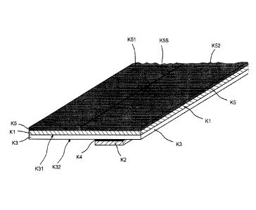
with a high tack are therefore used, in particular. Tack refers to the
stickiness to the touch
of an adhesive, in other words the quality thereof of bringing about immediate
adhesion to
a particular material.
Particularly for application in the paper industry or in the context of normal
newspaper
printing, high-tack adhesives are used advantageously on the facing side. It
may,
however, also be advantageous to use adhesives of high shear strength on the
facing
side. This is of interest in particular for application on the calender or in
use on the dryer.
Provided on the second surface (K32) of the carrier layer (K3) (referred to as
reverse
face, owing to the positioning of the adhesive tape on application in the
splicing
operation) is at least one second layer (K2) of adhesive, which in turn may be
provided
over the full area or only in regions of the second (reverse-face) surface.
In one very preferred embodiment the reverse-face layer (K2) of adhesive is
applied in
the form of a stripe (shown by way of example in Figure 5), which in one
advantageous
refinement of the adhesive tape (K) extends parallel to one of its edges
(LK1), in other
words, in particular, linearly. Advantageously a strip of adhesive ¨ more
particularly a
linear strip of adhesive ¨ of this kind extends in the longitudinal direction
(f) of the
CA 02935514 2016-07-08
18
adhesive tape, in other words on one or parallel to one of the long edges
(LK1) of the
adhesive tape.
Adhesive tapes customarily have an extent in a first direction (g) which is
very much
greater than the extent in a second direction (g) defined at right angles
thereto; this first
direction is therefore referred to for the purposes of this specification as
longitudinal
direction (0, and the extent in this direction as length (eK) of the adhesive
tape. The
second direction is referred to as cross direction (g.), and the extent in
this second
direction as width ((,,K) of the adhesive tape. The length (k) and the width
(tx) of the
adhesive tape determine its areal extent.
The thickness (aK) of the adhesive tape ¨ the extent in the third direction
(a) in the
Cartesian coordinate system, defined at right angles to the first and to the
second
direction and therefore to the areal extent of the adhesive tape ¨ is
customarily in turn
very much smaller than the width of the adhesive tape.
The adhesive tape of the invention may, however, also be present in the form
of adhesive
tape sections ("labels"), where the length and the width of the adhesive tape
are of similar
order of magnitude.
In one preferred embodiment the second (reverse-face) layer (K2) of adhesive
applied in
the form of a stripe is oriented parallel to its closest long edge (LK1) of
the adhesive tape
__ (K) and is indented at a distance (Al) from this long edge (LK1). The
indentation amounts
advantageously to up to 10 mm, preferably 0.5 to 5 mm, very preferably 1 to 3
mm. One
specific embodiment of the adhesive tape of the invention has an indentation
of 2 mm.
In another very preferred variant embodiment, the reverse-face layer (K2) of
adhesive is
provided in the form of a stripe which while running overall in the
longitudinal direction (g)
of the adhesive tape, does not itself have any linear edges. What this may
look like, for
instance, is that a linearly extending imaginary line can be defined in the
longitudinal
direction of the adhesive tape, running, in particular, parallel to at least
one of the long
edges (LK1) of the adhesive tape, with this line dividing the stripe of the
layer of adhesive
.. ¨ when this stripe is looked at straight on ¨ into two areal regions of
equal size. In a
preferred way the adhesive tape is formed conceptually by a sequence of
adhesive tape
sections for which in each case the corresponding section of adhesive located
thereon is
divided by the imaginary line into two parts of equal area.
CA 02935514 2016-07-08
19
A stripe of the invention with non-linear edges may be executed in such a way,
for
instance, that it has a left and a right boundary edge, at least one of these
two edges
being unstraight, such that the unstraight edge has projections which at their
positions of
maximum projection are continuously differentiatable and have a tangent
running parallel
to the imaginary line; more particularly, projections of a kind which are
executed in
rounded form at their points of maximum projection. Stripe forms of this kind
are defined
for example in EP 1 948 545 A. Explicit reference may be made to the line
forms
described in the claims of WO 2007/48695 A and EP 1 948 545 B and the line
forms
shown in the figures of those specifications ¨ especially in Figures 1, 2, 3,
4, 5, 6 and 7 of
WO 2007/48695 A ¨ together with the associated disclosure; these line forms
are also
outstandingly realisable for the present invention. Especially advantageous
are
symmetrical wave forms in accordance with Figure 7 of WO 2007/48695 A, and
variants
modified therefrom, for instance with a wavy edge and a straight edge, with
wavy edges
of different curvature, or with wavy edges whose maxima are displaced relative
to one
another. Hence it is possible, for example, also for edge shapes mirrored on
the
imaginary line to be realised.
A stripe of the invention with non-linear edges may also be executed such that
at least its
one boundary edge is designed in the form of a curve extending parallel to the
imaginary
line and is characterized by a sequence of rising and falling curve sections,
so that a
maximum or a plurality of maxima is or are formed between a respective rising
curve
section and a subsequent falling curve section in the curve region formed by
these two
curve sections, and so that a minimum or a plurality of minima is or are
formed between a
respective falling curve section and a subsequent rising curve section in the
curve region
formed by these two curve sections, the slope being different in magnitude in
each rising
curve section and in each falling curve section.
Curve profiles of this kind which are also advantageous for the present
invention are
shown for example by EP 2 130 887 A; explicit reference may be made to the
line forms
described in the claims and to the line forms shown in the figures of these
specifications ¨
particularly in Figures 2, 3, 3a, 4, 5, 6 and 7 ¨ including the associated
disclosure.
Further edge forms for stripe edges which run non-linearly and which may be
realised in
the sense of the present invention are shown by EP 2 615 049 A; reference may
be made
in particular to the claims and to Figures 2, 3, 4, 5, 6, 7, 8, 9 and the
associated
explanations, with the geometries shown there being transferred to a stripe in
accordance
with the present invention.
CA 02935514 2016-07-08
Provided on the second (reverse-face) surface there may also be two or more ¨
in each
case coherent ¨ first layers of adhesive, for instance in the form of two or
more ¨ mutually
unconnected ¨ partial coverings, segments, linear or non-linear ¨ for instance
undulatory ¨ stripes or the like.
5 An embodiment of this kind has two, three or more stripes running
parallel in the
longitudinal direction of the adhesive tape, between which and the second
surface of the
carrier layer there is in each case a surface coating provided for the purpose
of
generating predetermined breakage areas. It is of advantage if the first of
these stripes
has a distance from its closest long edge of the adhesive tape, as elucidated
above for
10 the adhesive tape with one stripe, in particular also with the
dimensions indicated there.
A system with two stripes may, for example, also have one stripe with at least
one non-
linear, more particularly undulatory edge ¨ in particular, two non-linear,
more particularly
undulatory edges ¨ as shown for instance in WO 2011/144466 A.
The extents of the reverse-face layers of adhesive are advantageously selected
such that
the desired splitting energy is obtained and that a secure adhesive bond is
ensured.
Through the form of the systems it is possible to influence the splitting
behaviour.
Relatively narrow predetermined breakage points ¨ i.e. those which are small
in relation
to the width of the main carrier ¨ offer the advantage that small fluctuations
in the
preselected parameters for the splitting operation are realisable.
Adhesive systems with a linear stripe form (those having two parallel edges in
the
longitudinal direction () of the adhesive tape) have, for example, in each
case and
independently of one another, widths (is) of 3 mm to 30 mm, particularly of 5
to 18 mm,
very particularly of 15 mm and of 9 mm. Undulatory adhesive systems may for
example
have widths (the width of stripes (is) which do not run linearly is taken to
be the maximum
extent of the respective stripe in cross direction (i)) of 20, 30 or 40 mm.
The aforesaid
figures, however, do not in principle confine the widths, the choice of which
is wide. If
there is only one stripe-shaped reverse-face layer of adhesive present, it is
likewise of
advantage to select the aforementioned dimensions for said layer.
Through the choice of the width of the reverse-face layers of adhesive, more
particularly
in stripe form, it is possible to adjust the splitting energy which must be
extended in order
to split the predetermined breakage point completely, independently from the
width of the
CA 02935514 2016-07-08
21
main carrier. This is an advantage relative to the systems wherein the
intended breakage
area extends over the full area of the width of the main carrier.
In advantageous adaptation to the particular application, it is possible with
preference
likewise to use a variant of the adhesive tape of the invention wherein the
only reverse-
face layer of adhesive present in stripe form or ¨ in the case of two or more
stripes ¨ the
reverse-face layer of adhesive closest to the long edge borders that long edge
directly, in
other words not being indented.
Adhesive used for the second, reverse-face layer of adhesive is advantageously
a shear-
resistant adhesive.
A fundamental objective is to make the adhesive tape of the invention as thin
as possible,
and so the thickness of the second layer of adhesive is generally likewise
selected to be
as thin as possible. In another embodiment, however, it is also possible for
the second
(reverse-face) layer of adhesive to be replaced by a multi-layer system which
comprises,
in addition to the bottom layer of adhesive, a carrier (secondary carrier)
and/or further
layers. In that case, for example, the reverse-face self-adhesive system may
be a double-
sided self-adhesive tape, especially if it is likewise provided in stripe
form.
Provided optionally on the second surface (reverse face) of the adhesive tape -
especially
in relation to specific applications of the adhesive splicing tape ¨ may be
third layers of
adhesive, for example in the regions of the surface or parts of these regions
in which no
surface coating is provided. The design of this third layer of adhesive may
for example be
such that it is not detachable from the second surface of the carrier.
At least the areal regions of the second surface that are provided with the
second layer of
adhesive are modified with the surface coating. In this case the surface layer
may be
provided exclusively in the regions of the second surface of the carrier layer
that are
covered by the second layer of adhesive; alternatively, the surface coating
may be
present in areas in which there is no second layer of adhesive. Hence the
surface
coating, for example, may be present over the full area of the second surface
of the
carrier layer, as is the case, for example, in general for coated papers where
the coat is
applied as early as part of the papermaking process.
CA 02935514 2016-07-08
22
In a further preferred embodiment the first, facing-side self-adhesive layer
(K1) is
provided with a release liner (K5) which is optionally provided with a
perforation or a slit
(K5S) in the longitudinal direction (IK).
Suitable for this purpose are the materials identified above. Very
advantageously it is
possible, for example, to use siliconized release paper. The slit (K5S) may be
provided
preferably at a distance (A2) of 10 to 40 mm from the long edge (LK2) of the
adhesive
tape (K), which is opposite the facing long edge (LK1) in whose vicinity the
second layer
(K2) of adhesive is arranged.
The second layer of adhesive may be provided over the full area or over part
of the area
on the reverse of the main carrier.
Advantageously an almost full-area implementation may be provided wherein
stripes with
which have no second adhesive and which are a few millimetres (for example in
each
case 1 or 2 mm) wide are provided on both long edges of the carrier.
In another very advantageous embodiment, the part of the reverse (K32) of the
carrier
(K3) that is furnished with one or more second layers (K2) of adhesive is up
to 60% of the
overall reverse-face area, preferably between 18 and 48%, it also being
possible for the
covered part of the reverse face to be divided into a plurality of areas, each
of which is
equipped with a second layer (K2) of adhesive.
The dimensions selected for the adhesive stripe of the invention may be
different
according to the field of use and the intended use and so may be adapted to
the
particular requirements. Advantageous product dimensions are, for example,
stripes of
75 mm width, of 63 mm width, of 50 mm width and of 38 mm width, without
wishing these
figures to impose any restriction.
The adhesive tape of the invention may be provided with perforations or
incisions such
that individual pieces of defined, predetermined length can be taken off.
In one advantageous embodiment the adhesive tape is equipped with at least one
means
recognizable by machine (contactlessly) by means of a detector, through
inductive
detection, for example, the recognition being achieved preferably by metal, by
transponder systems or by optical devices.
Such means recognizable optically or by machine may be provided in principle
in one or
more layers of the adhesive tape (carrier, layers of adhesive, other layers)
by the
admixing of appropriate additives into the material of the layer in question,
and/or the
CA 02935514 2016-07-08
23
means are provided as an independent layer or surface coating on existing
layers in the
adhesive tape assembly.
In one preferred variant, the carrier layer or regions thereof are composed of
a material
admixed with at least one detectable additive, and/or the carrier layer is an
assembly
which includes at least one layer of a detectable material.
In one embodiment of the inventive adhesive tape, for example, metal powders
or
granules are admixed to the actual carrier material, or the carrier framework
is provided
with one or more metal layers. In another variant of the inventive adhesive
tape, the
integrated signal function is realised by providing the carrier layer,
advantageously over
its full area, and in particular on its first surface, but optionally, instead
or additionally, on
its second surface, with an aluminium layer. Instead of aluminium, the layer
used may
also comprise all other materials detectable in accordance with the
requirements,
especially metals, for example copper, silver, gold.
Such layers are located advantageously on the facing side of the adhesive tape
or the
carrier layer.
Metal layers or metal coatings (of aluminium, for example) may also, instead
of being
present over the full area, be provided in the form of one or more stripes
which extend in
particular in the longitudinal direction of the adhesive tape of the
invention. In principle
such detectable layers may have any forms, such as segments, waves and the
like,
including irregular uninterrupted or interrupted forms.
In a further embodiment of the invention it is possible ¨alternatively or
additionally to add
mixtures in other layers, such as the carrier layer ¨ with the first layer of
adhesive and/or
the second layer of adhesive and/or, optionally, further layers of adhesive
present to have
been admixed with corresponding detectable additives ¨ metal powders or
granules, for
example.
In a further embodiment of the invention, the detection is brought about by
transponder
systems, more particularly by thin-film transponders, which are integrated
into the
adhesive tape. Here it is possible to realise versions with active and with
passive
transponders.
A feature of a further embodiment of the inventive adhesive tape is that the
adhesive tape
is provided with optically registerable means. These may be, for example, bar
codes
CA 02935514 2016-07-08
24
which can be read with a laser. When bar codes are used, in addition to the
detection
effect itself, information can be transmitted additionally, as for example
details concerning
the type or web thickness of the new roll. Thus when using rolls of different
kinds or
varieties, the processing unit can be set automatically to the new processing
conditions,
without further external control being required.
Functioning in a similar way are optical reflectors or diffraction gratings
mounted in or on
the carrier layer of the adhesive tape. These may likewise be detected
optically and
trigger the splicing operation.
A further example of optically detectable devices are particular colorations
of the carrier
layer and/or of the first layer of adhesive and/or of the second layer of
adhesive and/or of
functional layers and/or of any other layers present, which can likewise be
registered by
suitable detecting systems. Such colorations may be accomplished, for example,
through
the addition of black pigments.
Optically detectable devices may also be colour layers at any positions in the
layer
assembly of the adhesive tape, as for example on the top face of the carrier
layer, by
means of a black pigment line or black topcoat colour, for example. Colour
layers of this
kind may for example also be provided ¨ alternatively or additionally ¨
between the
underside of the main carrier layer and the surface coating which effects the
predetermined breakage point of the invention.
For the suitability of the adhesive tape of the invention in its intended use,
the forces
acting on the predetermined breakage area and required in order to initiate
the splitting
process in flying splice, and the force required to continue splitting of the
predetermined
breakage area, are of interest. These values ought to be set in such a way
that initial
splitting and continued splitting of the predetermined breakage point takes
place only
during use as intended, but then also does so reliably, without hindering the
flying splice
procedure. Advantageously here the splitting system ought to be set in such a
way as on
the one hand to prevent the risk of unwanted initial splitting in the
acceleration phase, and
on the other hand to ensure application-compatible splitting of the splicing
tape without
damage to the webs of material to be joined.
In order to overcome the splitting resistance of the facing edge, an increased
maximum
force is required for the initial splitting of the system (initial splitting
force, force for
initiating the splitting process of the predetermined breakage point).
Furthermore, a force
is required at a lower level for splitting over the entire width of the
splicing tape (continued
CA 02935514 2016-07-08
splitting force). The product of the force to be expended and the width of the
splitting
system is the energy that is needed for splitting (splitting energy).
The initial splitting force ought to be set at a high level such that the
product does not
open prematurely as a result of the aerodynamic forces and centrifugal forces
acting
5 during acceleration; on the other hand, the splitting energy must be low
enough that the
required energy for the complete splitting of the predetermined breakage area
right
through does not cause tearing. Values outstanding for these parameters can be
realised
by virtue of the configuration of the adhesive tapes of the invention.
10 To determine the initial splitting force (initial force for initiating
the splitting process of the
predetermined breakage point), swatch specimens are produced (for example in
DIN A4
size) which comprise a carrier layer having a first surface and a second
surface, there
being provided on the side of the first surface of the carrier layer,
indirectly or directly,
over the full area, a first layer of adhesive (corresponding to the
construction of the
15 adhesive tape for which the initial splitting force is to be
determined), and there being
provided on the second surface of the carrier layer, in particular over the
full area, a
second layer of adhesive, the second surface of the carrier layer having been
modified in
accordance with the invention with a surface coating, and the mandates of the
main claim
having been observed. Where examining adhesive tapes for which the
predetermined
20 breakage areas in the longitudinal direction of the adhesive tape have
interruptions (are
segmented), swatch specimens with a second adhesive layer interrupted
accordingly are
produced.
One edge of the swatch specimen is then cut off to give a smooth cut edge. A
piece of
paper of high tensile strength is placed onto the second layer of adhesive of
the
25 specimen under test, and the free surface of adhesive is lined with a
piece of siliconized
paper. The high-tensile paper is gently pressed with the finger in order to
prevent
inclusions of air. Thereafter, a manual roller is run twice quickly over the
assembly in
order to achieve excellent bond strength. The bond should be produced such
that the end
of the high-tensile paper protrudes beyond the adhesive tape body at the
smooth edge.
Using a steel ruler, strips are cut out on the sides of the smooth edge of the
assembly,
the width of the strips (parallel to the smooth edge) being 15 mm and their
length (at right
angles to the smooth edge) being about 20 cm, with the protruding paper end
located at
one of their ends. This protruding paper end serves subsequently as a grip
tab.
The apparatus for measuring the initial splitting force is shown
diagrammatically in
Figure 11. A sample M11 produced as described above is clamped into a tensile
testing
CA 02935514 2016-07-08
26
machine, the siliconized paper on the facing-side layer of adhesive is
removed, and the
sample is adhered firmly, with its now-exposed surface horizontal, on a
carrier M14 which
is clamped into the tensile machine (by means of clamping apparatus M16) (the
carrier
being at the bottom in the figure). The grip tab of the paper M12 on the
reverse-face layer
of adhesive is clamped into the tension unit (by means of clamping device M15)
of the
tensile testing machine. It should be ensured that the predetermined breakage
point has
not yet begun to split before measurement is commenced. The grip tab of the
paper M12
applied on the reverse-face layer of adhesive is then pulled at a speed of 300
m/min such
that the sample splits at an angle of 900. This splitting takes place in the
predetermined
breakage point. The initial force here is recorded (and corresponds to the
maximum of
the force-travel curve); the value measured is standardized, in knowledge of
the actual
specimen width, to 1 cm sample width. The average value from three
measurements is
reported (in N/cm).
For determining the continued splitting force, corresponding sample strips are
produced,
with the only difference that high-tensile papers with grip tabs are provided
both on the
surface of the first adhesive and on the surface of the second adhesive (on
the lower
surface instead of the siliconized paper).
For the measurement of the continued splitting force ¨ in this regard, see
Figure 12 ¨ the
sample M21 thus prepared is first of all initially split by hand at one of the
narrow edges
(indicated by the split M27 in Figure 12). The sample M21 is then clamped, at
both grip
tabs of the lining papers M22 and M23, into the clamping devices M25, M26 of a
tensile
testing machine, and fixed (by holding with the fingers, for example) in such
a way that it
stands perpendicularly to the two tensioning directions and that the splitting
process
continues at the split 27 when the tensile testing machine is put into
operation. Pulling is
carried out equally on both grip tabs, to continue sample splitting with a
speed of
300 mm/min at an angle of 180 . The splitting here takes place in the
predetermined
breakage point. The force reported is the force, standardized to 1 cm specimen
width,
which is needed in order to continue the splitting process (reported in
cN/cm).
The test conditions for all measurements are as follows: temperature 23 1 C;
50 5%
relative humidity, air pressure 1013 5 mbar.
In one preferred embodiment of the invention, the initial splitting force
required for splitting
of the predetermined breakage point of the adhesive tape of the invention is
in the range
CA 02935514 2016-07-08
27
from 0.1 N/cm up to 2.0 N/cm (newtons per centimetre bond width), and the
force
required to split the predetermined breakage area (continued splitting force)
is between 5
and 50 cN/cm.
The invention further relates to a splicing method for the on-the-fly roll
changeover of flat
web material wound up into rolls, more particularly as already set out briefly
above. The
method of the invention is shown by way of example in Figures 6 to 10.
Adhesive tapes
which can be used in accordance with the invention are shown by way of example
by
Figures 1 to 5.
In a method preferred in accordance with the invention, for preparation, the
flat web
section (R1) forming the uppermost turn of a roll (R) of a new flat web (RB)
is fastened to
the flat web section (R2) forming the underlying turn, with an adhesive tape
(K) which
comprises a carrier (K3) having a first (K31) and a second (K32) surface, a
first layer (K1)
of adhesive ¨ more particularly layer of self-adhesive -, which is provided
directly or
indirectly on the first surface (K31) of the carrier (K3), and a second layer
(K2) of
adhesive ¨ more particularly layer of self-adhesive -, which is provided over
at least part
of the area on the second surface (K32) of the carrier (K3). This is done
preferably in a
way as set out at the outset, so that an areal region (K12), required for the
splicing
method, of the facing-side, first layer (K1) of adhesive lies exposed (cf.
Figure 7).
Thereupon the new roll (R) thus furnished is placed adjacent to an almost
entirely
unwound old roll requiring replacement (not shown), and is accelerated to
substantially
the same peripheral speed as that roll (cf. Figure 8). The roll (R) is then
pressed against
the outgoing old web (B) of the old roll, with the exposed areal region of the
facing-side
layer (K12) of adhesive of the adhesive tape adhering to the old web (B) with
the webs at
.. substantially the same speeds. In order to increase the reliability of
bonding, it is
advantageous to carry out counter-pressing from the reverse face of the web,
during the
bonding operation, with a pressing means (roll, brush or the like) (A). In
this method an
adhesive tape (K) is used that has regions suitable for areal splitting
("predetermined
breakage areas"), by at least a part-region of the second surface of the
carrier layer (K3)
being modified with a surface coating (K4), the forces of adhesion of the
lower layer (K2)
of adhesive to the surface coating (K4) being greater than the forces of
adhesion of the
surface coating (K4) to the carrier layer (K3) and/or than the forces of
cohesion within the
surface coating (K4). Employed here in particular is an adhesive tape of the
invention as
described more closely in this specification and in the claims. At the same
time as or
.. immediately after adhesive bonding, there is adhesive fracture, at least in
the
CA 02935514 2016-07-08
28
predetermined breakage areas, between the surface coating (K4) and the carrier
layer
(K3) of the adhesive tape (K), or there is cohesive fracture within the
surface coating
(K4), and so, after the adhesive fracture or cohesive fracture, at least a
part-layer of the
surface coating (K4) masks the second layer (K2) of adhesive bonded on the old
web (B),
and there are no adhesive regions lying exposed there.
In an onward development of the inventive method, the adhesive tape (K) is
bonded at
right angles to the running flat web (RB). In one advantageous variant of the
inventive
method, the bonding of the adhesive tape (K) may also take place at an acute
angle of up
to 300 to the running flat web, more particularly of up to 50
.
In the splicing method, an adhesive tape (K) is bonded in a straight line
below the
uppermost turn (R1) of the new flat web (RB) to a new flat web roll (R). The
bonding here
is such that a part of the adhesive tape (K12) remains free for bonding with
the outgoing
web (B).
The adhesive tape (K) is preferably bonded in a straight line below the
uppermost turn
(R1) of the flat web (RB) of the new roll (R), so that a part (K12) of the
adhesive tape (K)
remains free, while the reverse-face layer(s) (R2) of adhesive of the adhesive
tape (K)
bond to the underlying flat web turn (R2) and so secure the uppermost web turn
(R1);
optionally, first of all, only part (K51) of the liner (K5) optionally located
on the first, facing-
side layer (K1) of adhesive has been removed, and so the part (K12) of the
layer (K1) of
adhesive that is required for the splicing method is still lined with the
liner (K52), and the
roll (R) in this state has no free adhesive area; then, for the subsequent
preparation of the
splicing method, any residual liner (K52) still present is removed, after
which the new roll
(R) thus equipped is placed adjacent to an almost completely unwound old roll
requiring
replacement (not shown) and is accelerated to substantially the same
peripheral speed
as that roll, then pressed against the outgoing old web (B) of the old roll,
with the exposed
region (K12) of the facing-side layer (K1) of adhesive of the adhesive tape
(K) bonding to
the old web (B) with the webs at substantially the same speeds, while at the
same time or
immediately thereafter the adhesive tape (K) splits essentially in the region
in which it is
equipped with the second, reverse-face layer (K2) of adhesive (or the second,
reverse-
face layers of adhesive) and non-adhesively masks the reverse-face layer or
layers (K2)
of adhesive with the surface coating (K4) detached from the carrier layer (K3)
in this
region, and/or with a part-layer of the surface coating (K4) split cohesively
in this region.
CA 02935514 2016-07-08
,
29
In a further variant, an adhesive tape of the invention is used in splicing
methods for
which the preparation of the new roll is accomplished not by bonding the
adhesive tape
below the web end of the new web, but instead by bonding it above. Adhesive
tape
versions and methods of this kind are described for example in specifications
EP 970 905 A or WO 2003/024850 A; the splicing methods depicted therein can be
outstandingly carried out likewise with corresponding adhesive tape versions
with
predetermined breakage points configured in accordance with the invention, and
are
intended to be encompassed by the invention.
Unexpectedly, the adhesive tape of the invention is outstandingly suitable for
flying splice.
Very advantageously, with the adhesive tape of the invention, the thickness of
the bond
site on transition from the old roll to the new roll can be greatly reduced,
and so the
problems described at the outset do not occur, or only to a very much reduced
extent.