Note: Descriptions are shown in the official language in which they were submitted.
CA 02935561 2016-07-08
COUPLING ASSEMBLY FOR CONNECTING A DRAIN TO A DRAIN PIPE
FIELD OF THE INVENTION
[0001] The present invention relates generally to pipe couplings, and more
specifically, to
a coupling assembly for connecting a drain to a drain pipe.
BACKGROUND OF THE INVENTION
100021 The need to connect a new drain to a drain pipe often arises during
building
renovations or refurbishment projects. In such instances, the new drain
usually includes an
insert pipe that has an outer diameter that is smaller than the outer diameter
of the drain
pipe. A variety of couplings have been developed to join the insert pipe to
the drain pipe.
For example, it is very common for installers to use a rubber flexible sleeve
coupling that
fits around and over the top of the standing drain pipe and the bottom of the
insert pipe, and
is tightly secured in place to each by circular steel band clamps are
tightened with screws.
While the design of this coupling sleeve is relatively simple and installation
of the coupling
can be performed relatively easily, the use of this type of coupling may not
be well-suited
in certain applications where access to the standing drain pipe may be limited
or difficult,
or where space constraints hinder the installer's ability to properly tighten
the steel band
clamps.
[0003] To address these drawbacks, certain couplings have been configured to
fit into the
insert pipe and the standing drain pipe. One such coupling is described in
Canadian Patent
No. 2,698,587 issued to Abbasi et al. The coupling includes an articulated
housing which
is made up of two solid tubular bodies that are threaded to each other. The
tubular bodies
are outfitted with an elastic tubular cover which surrounds them. The elastic
tubular cover
extends along almost the entire length of the tubular bodies and is held in
place by two end
collars - one collar associated with one of tubular bodies disposed at one end
of the
articulated housing and the other collar associated with the other tubular
bodies located at
the opposite end of the articulated housing. One of the collars is provided
with a castlehead
which is configured to receive a special, bar-shaped tool which allows torque
to be applied
to the associated tubular body.
CA 02935561 2016-07-08
-2-
100041 During installation, the articulated housing is inserted into the
insert pipe and then
both the articulated housing and the insert pipe are inserted into the
standing drain pipe.
Thereafter the special tool is mated with the castlehead provided on the
collar and the
associated tubular body is urged to rotate and move towards the other tubular
body. As this
occurs, the span between the two end collars shortens thereby squeezing or
compressing the
elastic tubular cover between the collars. This compression deforms the
elastic tubular
cover and causes it to expand outwardly to sealably contact the inner surfaces
of the insert
pipe and the standing drain pipe.
[0005] While this coupling constitutes an improvement over the rubber flexible
sleeve
described above, in the field some difficulties have been encountered. More
specifically,
due to its design, the elastic tubular body must be deformed in order to form
a seal with the
inner surfaces of both the insert pipe and the standing drain pipe. Sometimes,
during
installation, if the elastic tubular cover does not sufficiently deform, it
can fall through the
standing drain pipe and can get lodged therein. Retrieval of the lodged
coupling can be a
difficult and costly undertaking.
[0006] A similar problem can be encountered when an installer wishes to
disconnect an
already installed coupling. It is not possible to separately disconnect the
coupling from the
insert pipe or the standing drain pipe. In order to disconnect an already
installed coupling,
the installer has to lengthen the tubular bodies to cause the elastic tubular
cover to revert to
its non-expanded configuration. When the installer does so, the coupling is
simultaneously
loosened from both the insert pipe and the standing drain pipe.
[0007] Moreover, because of the rigidity and limited sizing options of the
tubular bodies,
the coupling cannot accommodate a broad range of pipe sizes.
[0008] In light of the foregoing, it would be desirable to have a coupling
assembly that
could be tighten or "locked" in place to each of the standing pipe drain and
the insert pipe,
independently. Preferably, such coupling assembly would be configured to
minimize the
risk of it falling into, and becoming lodged in, the standing drain pipe.
CA 02935561 2016-07-08
- 3 -
SUMMARY OF THE INVENTION
[0009] In accordance with one embodiment of the present invention, there is
provided a
kit for coupling a drain having an insert pipe to a drain pipe. The kit
includes a coupling
sleeve made of a resiliently deformable, elastomeric material. The coupling
sleeve has a
tubular sleeve body provided with an inner surface; a top end sized to snugly
fit within the
insert pipe of the drain; a top circumferential groove defined in the inner
surface of the
sleeve body at a location proximate the top end of the sleeve body; a bottom
end sized to
snugly fit within the drain pipe; and a bottom circumferential groove defined
in the inner
surface of the sleeve body at a location proximate the bottom end of the
sleeve body. The
thickness of the sleeve body is variable along the top and bottom
circumferential grooves.
The kit also includes a top expansion ring which is made of a rigid material
and which is
seized to snugly fit within the top groove. The top expansion ring has a
plurality of
outwardly projecting structures at spaced apart locations configured to abut
the inner
surface of the sleeve body. When operatively connecting the coupling sleeve to
the insert
pipe of the drain, the top expansion ring is rotatable within the top groove
to position at
least one of the plurality of outwardly projecting structures of the top
expansion ring
against an area of the sleeve body having increased thickness so as to urge
the coupling
sleeve in the region of top groove to bulge outwardly and seal the coupling
sleeve against
the insert pipe. Also provided is a bottom expansion ring made of a rigid
material. The
bottom expansion ring is sized to snugly fit within the bottom groove and has
a plurality of
outwardly projecting structures at spaced apart locations to abut the inner
surface of the
sleeve body. When operatively connecting the coupling sleeve to the drain
pipe, the bottom
expansion ring is rotatable within the bottom groove to position at least one
of the plurality
of outwardly projecting structures of the bottom expansion ring against an
area of the
sleeve body having increased thickness so as to urge the coupling sleeve in
the region of
bottom groove to bulge outwardly and seal the coupling sleeve against the
drain pipe.
[0010] In one feature, the sleeve body has a top portion, a bottom portion,
and
intermediate portion joining the top portion to the bottom portion. The top
portion has a
diameter that is sized smaller than the diameter of the bottom portion.
Optionally, the
sleeve body has helical threading projecting from the outer surface thereof.
CA 02935561 2016-07-08
-4-
100111 In another feature, the top circumferential groove has a plurality of
top sleeve
abutment shoulders formed into the inner surface of the sleeve body. The
thickness of the
sleeve body along the top circumferential groove is greatest at the locations
of the plurality
of top sleeve abutment shoulders. The coupling sleeve in the region of top
groove has a
non-expanded configuration and an expanded configuration. When the coupling
sleeve is in
the non-expanded configuration, at least one of the plurality of outwardly
projecting
structures of the top expansion ring abuts at least one of the top sleeve
abutment shoulders.
When the coupling sleeve is in the expanded configuration, at least one of the
plurality of
outwardly projecting structures of the top expansion ring is displaced from at
least one of
the top sleeve abutment shoulders.
[0012] In a further feature, the plurality of top sleeve abutment shoulders
includes six top
sleeve abutment shoulders. Each of the plurality of outwardly projecting
structures of the
top expansion ring is a top ring abutment shoulder. The plurality of outwardly
projecting
structures of the top expansion ring includes six top ring abutment shoulders.
In an
alternative feature, the plurality of top sleeve abutment shoulders includes
four top sleeve
abutment shoulders. Each of the plurality of outwardly projecting structures
of the top
expansion ring is a top ring abutment shoulder. The plurality of outwardly
projecting
structures of the top expansion ring includes four top ring abutment
shoulders.
[0013] In an additional feature, the top circumferential groove includes a
plurality of
curved rebate regions disposed in a ring-like arrangement. Each curved rebate
region is
bound by a pair of the top sleeve abutment shoulders. In at least one of the
plurality of
curved rebate regions, the thickness of the sleeve body gradually increases
between the pair
of top sleeve abutment shoulders that bound the at least one of the plurality
of curved rebate
regions.
[0014] In another feature, the bottom circumferential groove is formed with a
plurality of
bottom sleeve abutment shoulders formed into the inner surface of the sleeve
body. The
thickness of the sleeve body along the bottom circumferential groove is
greatest at the
location of bottom sleeve abutment shoulders. The coupling sleeve in the
region of bottom
groove has a non-expanded configuration and an expanded configuration. When
the
CA 02935561 2016-07-08
- 5 -
coupling sleeve is in the non-expanded configuration, at least one of the
plurality of
outwardly projecting structures of the bottom expansion ring abuts at least
one of the
bottom sleeve abutment shoulders. When the coupling sleeve is in the expanded
configuration, at least one of the plurality of outwardly projecting
structures of the bottom
expansion ring is displaced from at least one of the bottom sleeve abutment
shoulders.
[0015] In a further feature, the plurality of bottom sleeve abutment shoulders
includes six
bottom sleeve abutment shoulders. Each of the plurality of outwardly
projecting structures
of the bottom expansion ring is a bottom ring abutment shoulder. The plurality
of
outwardly projecting structures of the bottom expansion ring includes six
bottom ring
abutment shoulders. In an alternative feature, the plurality of bottom sleeve
abutment
shoulders includes four bottom sleeve abutment shoulders. Each of the
plurality of
outwardly projecting structures of the bottom expansion ring is a bottom ring
abutment
shoulder. The plurality of outwardly projecting structures of the bottom
expansion ring
includes four bottom ring abutment shoulders.
[0016] In
an additional feature, the bottom circumferential groove includes a plurality
of
curved rebate regions disposed in a ring-like arrangement. Each curved rebate
region is
bound by a pair of the bottom sleeve abutment shoulders. In at least one of
the plurality of
curved rebate regions, the thickness of the sleeve body gradually increases
between the pair
of bottom sleeve abutment shoulders that bound the at least one of the
plurality of curved
rebate regions.
[0017] In yet another feature, the top expansion ring is sized smaller than
the bottom
expansion ring. The number of outwardly projecting structures of the top
expansion ring
matches the number of outwardly projecting structures of the bottom expansion
ring.
[0018] In still another feature, the top circumferential groove has a
plurality of top sleeve
abutment shoulders formed into the inner surface of the sleeve body. The
bottom
circumferential groove has a plurality of bottom sleeve abutment shoulders
formed into the
inner surface of the sleeve body. The number of top sleeve abutment shoulders
matches the
number of bottom sleeve abutment shoulders.
CA 02935561 2016-07-08
- 6 -
[0019] In a further feature, the kit further includes a top key fitting
configured to mate
with the top expansion ring for fixed rotation therewith. The top key fitting
is attachable to
a tool. The top expansion ring has a central cutout whose boundaries are
defined by a
plurality of contoured portions disposed in a ring-like arrangement. Each
contoured portion
includes a landing configured to receive a portion of the top key fitting. The
top key fitting
has a body and a plurality of spaced apart stub arms projecting outwardly
therefrom. Each
stub arm is configured to fit within one landing of a respective contoured
portion.
Optionally, the plurality of contoured portions includes six contoured
portion. In a further
option, the plurality of contoured portions includes four contoured portion.
[0020] In an additional feature, the kit includes a bottom key fitting
configured to mate
with the bottom expansion ring for fixed rotation therewith. The bottom key
fitting is
attachable to a tool. The bottom expansion ring has a central cutout whose
boundaries are
defined by a plurality of contoured portions disposed in a ring-like
arrangement. Each
contoured portion including a landing configured to receive a portion of the
bottom key
fitting. The bottom key fitting has a disc-shaped body and a plurality of
spaced apart stub
arms radiating therefrom. Each stub arm configured to fit within one landing
of a respective
contoured portion. Optionally, the plurality of contoured portions includes
six contoured
portion. In a further option, the plurality of contoured portions includes
four contoured
portion.
[0021] In yet another feature, the kit includes a top key fitting and a bottom
key fitting.
The top key fitting is configured to mate with the top expansion ring for
fixed rotation
therewith. The bottom expansion ring is configured to mate with the bottom
expansion ring
for fixed rotation therewith. Each of the key fittings is attachable to a
tool. The top key
fitting is sized smaller than the bottom key fitting.
[0022] In another broad aspect of the present invention, there is provided a
kit for
coupling a first pipe to a second pipe. The kit includes a coupling sleeve
made of a
resiliently deformable, elastomeric material. The coupling sleeve has a
tubular sleeve body
provided with an inner surface; a top end sized to snugly fit within the first
pipe; a top
circumferential groove defined in the inner surface of the sleeve body at a
location
CA 02935561 2016-07-08
- 7 -
proximate the top end of the sleeve body; a bottom end sized to snugly fit
within the second
pipe; a bottom circumferential groove defined in the inner surface of the
sleeve body at a
location proximate the bottom end of the sleeve body. The thickness of the
sleeve body is
variable along the top and bottom circumferential grooves. The kit further
includes a top
expansion ring made of a rigid material. The top expansion ring is sized to
snugly fit within
the top groove and has a plurality of outwardly projecting structures at
spaced apart
locations configured to abut the inner surface of the sleeve body. When
operatively
connecting the coupling sleeve to the first pipe, the top expansion ring is
rotatable within
the top groove to position at least one of the plurality of outwardly
projecting structures of
the top expansion ring against an area of the sleeve body having increased
thickness so as
to urge the coupling sleeve in the region of top groove to bulge outwardly and
seal the
coupling sleeve against the first pipe. Also provided is a bottom expansion
ring made of a
rigid material. The bottom expansion ring is sized to snugly fit within the
bottom groove
and has a plurality of outwardly projecting structures at spaced apart
locations to abut the
inner surface of the sleeve body. When operatively connecting the coupling
sleeve to the
second pipe, the bottom expansion ring is rotatable within the bottom groove
to position at
least one of the plurality of outwardly projecting structures of the bottom
expansion ring
against an area of the sleeve body having increased thickness so as to urge
the coupling
sleeve in the region of bottom groove to bulge outwardly and seal the coupling
sleeve
against the second pipe.
[0023] In yet another broad aspect of the present invention, there is provided
a kit for
coupling a first pipe to a second pipe. The kit includes a coupling sleeve
made of a
resiliently deformable, elastomeric material. The coupling sleeve has a
tubular sleeve body
provided with an inner surface; a first end sized to snugly fit within the
first pipe; a first
circumferential groove defined in the inner surface of the sleeve body at a
location
proximate the first end of the sleeve body; a second end sized to snugly fit
within the
second pipe; a second circumferential groove defined in the inner surface of
the sleeve
body at a location proximate the second end of the sleeve body. The thickness
of the sleeve
body is variable along the first and second circumferential grooves. The kit
further includes
a first expansion ring made of a rigid material. The first expansion ring is
sized to snugly fit
within the first groove and has a plurality of outwardly projecting structures
at spaced apart
CA 02935561 2016-07-08
- 8 -
locations configured to abut the inner surface of the sleeve body. When
operatively
connecting the coupling sleeve to the first pipe, the first expansion ring is
rotatable within
the first groove to position at least one of the plurality of outwardly
projecting structures of
the first expansion ring against an area of the sleeve body having increased
thickness so as
to urge the coupling sleeve in the region of first groove to bulge outwardly
and seal the
coupling sleeve against the first pipe. Also provided is a second expansion
ring made of a
rigid material. The second expansion ring is sized to snugly fit within the
bottom groove
and has a plurality of outwardly projecting structures at spaced apart
locations to abut the
inner surface of the sleeve body. When operatively connecting the coupling
sleeve to the
second pipe, the second expansion ring is rotatable within the second groove
to position at
least one of the plurality of outwardly projecting structures of the second
expansion ring
against an area of the sleeve body having increased thickness so as to urge
the coupling
sleeve in the region of second groove to bulge outwardly and seal the coupling
sleeve
against the second pipe.
100241 In still another broad aspect of the present invention, there is
provided a kit for
coupling a first pipe to a second pipe. The kit includes a coupling sleeve
made of a
resiliently deformable, elastomeric material. The coupling sleeve has a
tubular sleeve body
that includes a top portion, a bottom portion, an intermediate portion
disposed between the
top and bottom portions and an inner surface defining a passageway extending
through the
top, intermediate and bottom portions. The passageway has a first portion
extending
between the top portion and the intermediate portion and a second portion
extending
between the intermediate portion and the bottom portion. The first portion of
the
passageway tapers from the top portion toward the intermediate portion and has
threading
formed along the inner surface. The second portion of the passageway tapers
from the
bottom portion toward the intermediate portion and has threading formed along
the inner
surface. The sleeve body further includes a top end sized to snugly fit within
the insert pipe
of the drain and a bottom end sized to snugly fit within the drain pipe. A top
expansion ring
is also provided. It is made of a rigid material and has threading formed
along its outer
surface configured for engagement with the threading formed along the inner
surface of the
first portion of the passageway. When operatively connecting the coupling
sleeve to the
insert pipe of the drain, the top expansion ring is threadingly engageable
with the top
CA 02935561 2016-07-08
- 9 -
portion of the coupling sleeve so as to urge the coupling sleeve in the region
of top
expansion ring to bulge outwardly and seal the coupling sleeve against the
insert pipe. The
kit further has a bottom expansion ring made of a rigid material. The bottom
expansion ring
has threading formed along its outer surface configured for engagement with
the threading
formed along the inner surface of the second portion of the passageway. When
operatively
connecting the coupling sleeve to the drain pipe, the bottom expansion ring is
threadingly
engageable with the bottom portion of the coupling sleeve so as to urge the
coupling sleeve
in the region of bottom expansion ring to bulge outwardly and seal the
coupling sleeve
against the drain pipe.
[0025] In another feature, the top portion of the sleeve body has a diameter
that is sized
smaller than the diameter of the bottom portion. In a further feature, the
sleeve body has
helical threading projecting from the outer surface thereof
[0026] In yet another feature, the sleeve body has a sleeve body wall and the
thickness of
the sleeve body wall increases from each of the top and bottom ends of the
sleeve body
towards the intermediate portion. In still another feature, the top expansion
ring is sized
smaller than the bottom expansion ring.
[0027] In additional feature, the kit further includes a key fitting
configured to mate with
at least one of the top and bottom expansion rings for fixed rotation
therewith. The key
fitting is attachable to a tool. Optionally, the key fitting is configured to
mate with the top
expansion ring and the bottom expansion ring. In another feature, the key
fitting has a body
and a plurality of spaced apart stub arms projecting outwardly therefrom. In
one feature,
the key fitting has four stub arms.
100281 In a further feature, the top expansion ring has an inner surface that
defines a
central cutout and includes a plurality of spaced apart landings cut into the
inner surface of
the top expansion ring at locations about the central cutout. Each landing is
configured to
receive one of the stub arms of the key fitting. The top expansion ring also
has a top face
and a bottom face and the plurality of landings extend into the bottom face of
the top
expansion ring. In an additional feature, the top expansion ring has a
plurality of grooves
CA 02935561 2016-07-08
- 10 -
that extend through the top and bottom faces. Each groove of the plurality is
shaped to
allow one of the stub arms of the key fitting to pass therethrough.
[0029] In yet another feature, the bottom expansion ring has an inner surface
that defines
a central cutout and includes a plurality of spaced apart landings cut into
the inner surface
of the bottom expansion ring at locations about the central cutout. Each
landing is
configured to receive one of the stub arms of the key fitting. The bottom
expansion ring
has a top face and a bottom face and the plurality of landings extend into the
top face of the
bottom expansion ring.
[0030] In still another broad aspect of the present invention, there is
provided a kit for
coupling a first pipe to a second pipe. The kit includes a coupling sleeve
made of a
resiliently deformable, elastomeric material. The coupling sleeve has a
tubular sleeve body
that includes a top portion, a bottom portion, an intermediate portion
disposed between the
top and bottom portions and an inner surface defining a passageway extending
through the
top, intermediate and bottom portions. The passageway has a first portion
extending
between the top portion and the intermediate portion and a second portion
extending
between the intermediate portion and the bottom portion. The first portion of
the
passageway tapers from the top portion toward the intermediate portion and has
threading
formed along the inner surface. The second portion of the passageway tapers
from the
bottom portion toward the intermediate portion and has threading formed along
the inner
surface. The sleeve body also includes a top end sized to snugly fit within
the first pipe and
a bottom end sized to snugly fit within the second pipe. The kit is further
provided with a
top expansion ring made of a rigid material. The top expansion ring has
threading formed
along its outer surface configured for engagement with the threading formed
along the
inner surface of the first portion of the passageway. When operatively
connecting the
coupling sleeve to the first pipe, the top expansion ring is threadingly
engageable with the
top portion of the coupling sleeve so as to urge the coupling sleeve in the
region of top
expansion ring to bulge outwardly and seal the coupling sleeve against the
first pipe. Also
included in the kit is a bottom expansion ring made of a rigid material. The
bottom
expansion ring has threading formed along its outer surface configured for
engagement
with the threading formed along the inner surface of the second portion of the
passageway.
CA 02935561 2016-07-08
- 11 -
When operatively connecting the coupling sleeve to the second pipe, the bottom
expansion
ring is threadingly engageable with the bottom portion of the coupling sleeve
so as to urge
the coupling sleeve in the region of bottom expansion ring to bulge outwardly
and seal the
coupling sleeve against the second pipe.
[0031] In a different broad aspect of the present invention, there is provided
a kit for
coupling a first pipe to a second pipe. The kit includes a coupling sleeve
made of a
resiliently deformable, elastomeric material. The coupling sleeve has a
tubular sleeve body
that includes a first body portion, a second body portion, an intermediate
body portion
disposed between the first and second body portions and an inner surface
defining a
passageway extending through the first, intermediate and second body portions.
The
passageway has a first passageway portion extending between the first body
portion and the
intermediate body portion and a second passageway portion extending between
the
intermediate body portion and the bottom body portion. The first passageway
portion
tapers from the top body portion toward the intermediate body portion and has
threading
formed along the inner surface. The second passageway portion tapers from the
bottom
body portion toward the intermediate body portion and has threading formed
along the
inner surface. The sleeve body also has a first end sized to snugly fit within
the first pipe
and a second end sized to snugly fit within the second pipe. The kit further
includes a first
expansion ring made of a rigid material. The first expansion ring has
threading formed
along its outer surface configured for engagement with the threading formed
along the
inner surface of the first passageway portion. When operatively connecting the
coupling
sleeve to the first pipe, the first expansion ring is threadingly engageable
with the first body
portion of the coupling sleeve so as to urge the coupling sleeve in the region
of first
expansion ring to bulge outwardly and seal the coupling sleeve against the
first pipe. Also
provided is a second expansion ring made of a rigid material. The second
expansion ring
has threading formed along its outer surface configured for engagement with
the threading
formed along the inner surface of the second passageway portion. When
operatively
connecting the coupling sleeve to the second pipe, the second expansion ring
is threadingly
engageable with the second body portion of the coupling sleeve so as to urge
the coupling
sleeve in the region of second expansion ring to bulge outwardly and seal the
coupling
sleeve against the second pipe.
CA 02935561 2016-07-08
- 12 -
BRIEF DESCRIPTION OF THE DRAWINGS
[0032] The embodiments of the present invention shall be more clearly
understood with
reference to the following detailed description of the embodiments of the
invention taken in
conjunction with the accompanying drawings, in which:
[0033] FIG. 1 is a top right perspective view of a coupling assembly for a
drain pipe
according to an embodiment of the present invention;
[0034] FIG. 2 is a side elevation view of the coupling assembly shown in FIG.
1;
[0035] FIG. 3 is a bottom plan view showing the coupling assembly illustrated
in FIG. 1
with a bottom expansion ring disposed within a coupling sleeve being visible
therein;
[0036] FIG. 4 is a top plan view showing the coupling assembly illustrated in
FIG. 1 with
an top expansion ring disposed within the coupling sleeve being visible
therein;
[0037] FIG. 5 is a cross-sectional view of the coupling assembly illustrated
in FIG. 2
taken along section '5-5' showing the bottom expansion ring positioned within
the coupling
sleeve while the lower portion of the coupling sleeve remains in a non-
expanded
configuration;
[0038] FIG. 6 is another cross-sectional view similar to that illustrated in
FIG. 5 except
that the bottom expansion ring has been removed to reveal details of the
internal structure
of the coupling sleeve in the region of the bottom groove;
[0039] FIG. 7 is another cross-sectional view of the coupling assembly
illustrated in FIG.
2 taken along section '7-7' showing the top expansion ring positioned within
the coupling
sleeve while the upper portion of the coupling sleeve remains in a non-
expanded
configuration;
[0040] FIG. 8 is another cross-sectional view similar to that illustrated in
FIG. 7 except
that the top expansion ring has been removed to reveal details of the internal
structure of
the coupling sleeve in the region of the top groove;
CA 02935561 2016-07-08
- 13 -
[0041] FIG. 9 is an exploded view of the coupling assembly shown in FIG. 1;
[0042] FIG. 10 is a cross-sectional view of the coupling sleeve shown in FIG.
1 taken
along section '9-9';
[0043] FIG. 11 is a top plan view of the bottom expansion ring illustrated in
FIG. 10;
[0044] FIG. 12 is a bottom plan view of the bottom expansion ring shown in
FIG. 10;
[0045] FIG. 13 is a longitudinal cross-sectional view showing the coupling
assembly
illustrated in FIG. 1 being operatively connected to the insert pipe of the
drain using a
ratchet tool;
[0046] FIG. 14 is a cross-sectional view similar to that illustrated in FIG. 5
showing the
key fitting of the ratchet tool being used to rotate the top expansion ring
within the coupling
sleeve so as to urge the top portion of the coupling sleeve to adopt an
expanded or bulging
configuration;
[0047] FIG. 15 is another longitudinal cross-sectional view showing the
coupling
assembly illustrated in FIG. 1 being operatively connected to the standing
drain pipe using
the ratchet tool;
[0048] FIG. 16 is another cross-sectional view similar to that illustrated in
FIG. 7
showing the key fitting of the ratchet tool being used to rotate the bottom
expansion ring
within the coupling sleeve so as to urge the bottom portion of the coupling
sleeve to adopt
an expanded or bulging configuration;
[0049] FIG. 17 is a longitudinal cross-sectional view of the drain, the
coupling
assembly and the drain pipe all shown operatively connected to each other;
[0050] FIG. 18 is a front right perspective view of another coupling assembly
according
to an alternative embodiment to that shown in FIG. 1;
[0051] FIG. 19 is an exploded view of the coupling assembly shown in FIG. 18;
CA 02935561 2016-07-08
- 14 -
[0052] FIG. 20 is a cross-sectional view of the coupling assembly illustrated
in FIG. 18
taken along section '20-20' showing the bottom expansion ring positioned
within the
coupling sleeve while the lower portion of the coupling sleeve remains in a
non-expanded
configuration;
[0053] FIG. 21 is another cross-sectional view similar to that illustrated in
FIG. 20
except that the bottom expansion ring has been removed to reveal details of
the internal
structure of the coupling sleeve in the region of the bottom groove; and
[0054] FIG. 22 is a cross-sectional view similar to that illustrated in FIG.
20 showing an
alternative key fitting of the ratchet tool being used to rotate the bottom
expansion ring
within the coupling sleeve so as to urge the bottom portion of the coupling
sleeve to adopt
an expanded or bulging configuration;
[0055] FIG. 23 is a cross-sectional view of the coupling assembly illustrated
in FIG. 18
taken along section '23-23' showing the top expansion ring positioned within
the coupling
sleeve while the upper portion of the coupling sleeve remains in a non-
expanded
configuration, the lower portion of the coupling sleeve being omitted for
purposes of
clarity;
[0056] FIG. 24 is another cross-sectional view similar to that illustrated in
FIG. 23
except that the top expansion ring has been removed to reveal details of the
internal
structure of the coupling sleeve in the region of the top groove;
[0057] FIG. 25 is a cross-sectional view similar to that illustrated in FIG.
23 showing an
alternative key fitting of the ratchet tool being used to rotate the top
expansion ring within
the coupling sleeve so as to urge the upper portion of the coupling sleeve to
adopt an
expanded or bulging configuration;
[0058] FIG. 26 is a top right perspective view of a coupling assembly for a
drain pipe
according to a further embodiment of the present invention;
[0059] FIG. 27 is a side elevation view of the coupling assembly shown in FIG.
26;
CA 02935561 2016-07-08
- 15 -
[0060] FIG. 28 is a bottom plan view showing the coupling assembly illustrated
in FIG.
26 with a bottom expansion ring disposed within a coupling sleeve being
visible therein;
[0061] FIG. 29 is a top plan view showing the coupling assembly illustrated in
FIG. 26
with an top expansion ring disposed within the coupling sleeve being visible
therein;
[0062] FIG. 30 is a cross-sectional view of the coupling assembly illustrated
in FIG. 27
taken along section '30-30' showing the top and bottom expansion rings
positioned within
the coupling sleeve with the upper and lower portions of the coupling sleeve
remaining in a
non-expanded configuration;
[0063] FIG. 31 is an exploded view of the coupling assembly shown in FIG. 26;
[0064] FIG. 32 is a cross-sectional view of the coupling sleeve similar to
that shown
in FIG. 30, except that the top and bottom expansion rings have been omitted
to reveal
details of the interior of the coupling sleeve;
[0065] FIG. 33 is a top plan view of the bottom expansion ring illustrated in
FIG. 29;
100661 FIG. 34 is a bottom plan view of the bottom expansion ring shown in
FIG. 29;
[0067] FIG. 35 is a top plan view of the top expansion ring illustrated in
FIG. 28;
[0068] FIG. 36 is a bottom plan view of the top expansion ring shown in FIG.
28;
[0069] FIG. 37 is a longitudinal cross-sectional view showing the coupling
assembly
illustrated in FIG. 26 being operatively connected to the insert pipe of the
drain using a
ratchet tool;
[0070] FIG. 38 is a cross-sectional view of the coupling assembly deployed
within the
insert pipe shown in FIG. 37 along taken along section '38-38' showing the key
fitting of
the ratchet tool being used to rotate the top expansion ring and advance it
further downward
into the coupling sleeve;
CA 02935561 2016-07-08
- 16 -
[0071] FIG.
39 is another longitudinal cross-sectional view showing the coupling
assembly illustrated in FIG. 26 being operatively connected to the standing
drain pipe using
the ratchet tool;
[0072] FIG. 40 is another cross-sectional of the coupling assembly deployed
within the
standing drain pipe shown in FIG. 39 along taken along section '40-40' showing
the key
fitting of the ratchet tool being used to rotate the bottom expansion ring and
advance it
further upward into the coupling sleeve; and
[0073] FIG. 41 is a longitudinal cross-sectional view of the drain, the
coupling
assembly and the drain pipe all shown operatively connected to each other.
DETAILED DESCRIPTION OF THE EMBODIMENTS OF THE INVENTION
[0074] The description which follows, and the embodiments described therein
are
provided by way of illustration of an example, or examples of particular
embodiments of
principles and aspects of the present invention. These examples are provided
for the
purposes of explanation and not of limitation, of those principles of the
invention. In the
description that follows, like parts are marked throughout the specification
and the
drawings with the same respective reference numerals.
[0075] Referring to FIGS. 1, 9, 17, there is shown a coupling assembly 20 for
sealably
connecting a drain 22 having an insert pipe 24 to a standing drain pipe 26. In
the preferred
embodiment, coupling assembly 20 is vertically oriented, the drain 22 is a
roof drain
mountable to a roof structure 23 and the drain pipe 26 is a roof drain pipe
projecting
upwardly through an opening 25 formed through a support structure 27 that is
located
below the roof structure 23. However, this need not be the case in every
application. In
alternative embodiments, the coupling assembly 20 could be used with other
drains and
drain pipes disposed differently. In still other embodiments, the coupling
assembly could
be used to connect horizontally-oriented pipes.
[0076] Given the vertical orientation of the coupling assembly 20 in the
preferred
embodiment, in this specification, the terms upper (or top) and lower (or
bottom) will be
used to describe the orientation of components of the assembly 20.
CA 02935561 2016-07-08
- 17 -
[0077] As shown in FIG. 9, coupling assembly 20 includes a flexible coupling
sleeve 28, a
rigid bottom expansion ring 30 and a rigid top expansion ring 32. The coupling
sleeve 28 is
made of a fluid impermeable, elastomeric material (preferably, ethylene
propylene diene
monomer (EPDM) rubber) and has a generally tubular sleeve body 34 which
extends
between a top end 36 and a bottom end 38 (see FIGS. 2 and 10). In this
embodiment, the
length of the sleeve body 34 measures 120 mm. In other embodiments, the sleeve
body
could be sized differently to suit a particular application.
[0078] The sleeve body 34 has an outer surface 40 and an inner surface 42
which defines
a longitudinal passageway 44 that communicates with a top opening 46 and a
bottom
opening 48. Disposed helically along the outer surface 40 of the sleeve body
34 between
the top and bottom ends 36 and 38 and formed thereon, is raised helical
threading 50. As
explained below, the threading 50 serves to enhance the seal made between, on
the one
hand, the coupling sleeve 28 and the inner surface 52 of the insert pipe 24
(visible in FIG.
15) on the one hand, and on the other hand, the coupling sleeve 20 and the
inner surface 54
of the standing drain pipe 26 (visible in FIG. 13).
[0079] As shown in FIG. 17, the sleeve body 30 further includes a lower
portion 56
provided with an outer diameter DL (measured about the outer surface 40, but
excluding the
threading 50), an upper portion 58 provided with a relatively smaller outer
diameter Du
(also measured about the outer surface 40, but excluding the threading 50) and
an
intermediate transition portion 60 joining the lower portion 56 to the upper
portion 58. The
outer diameter Di is sized to be smaller than the internal diameter DDp of the
standing drain
pipe 26 (shown in Fig. 17) such that the lower portion 56 can fit snugly
within the standing
drain pipe 26, when the coupling sleeve 28 is inserted therein. Similarly, the
outer diameter
Du of the upper portion 58 is sized to be smaller than the internal diameter
D1p of the insert
pipe 24 (shown in Fig. 17) to allow the top portion 58 to fit snugly within
the insert pipe 24,
when the coupling sleeve 28 is connected to the drain 22. It should be noted
that in this
arrangement, the internal diameter D1p of the insert pipe 24 is relatively
smaller than the
internal diameter DDp of the standing drain pipe 26. In this embodiment, the
DL measures
73 mm; the Du measures 63 mm; the DDp measures 75 mm; and the Dip measures 65
mm.
These are merely examples of suitable dimensions. In other embodiments, the
insert pipe
CA 02935561 2016-07-08
- 18 -
and the standing drain pipe could have different internal diameters, in which
case the upper
and lower portions would be configured with appropriately sized smaller outer
diameters to
ensure a good seal is formed between the coupling assembly and each of the
insert pipe and
the standing drain pipe.
[0080] The intermediate portion 60 is relatively narrow and is formed roughly
midway
between the upper and lower portions 58 and 56. In the region of the
intermediate portion
60, the sleeve body 34 tapers gently in the direction of the upper portion 58
before
terminating with a very short flange 62 (clearly identified in FIGS. 2 and 10)
that connects
to the upper portion 58.
[0081] Referring specifically to FIG. 10, one can see that the internal
diameter within the
passageway 44 is relatively larger in the area of the lower portion 56 than in
the area of the
upper portion 58 with the internal diameter tapering in the intermediate
portion 60.
[0082] At a short distance away from the bottom opening 48, a first station in
the nature
of a circumferential bottom groove 64 is defined in the inner surface 42 of
the sleeve body
34. The bottom groove 64 is configured to accommodate therein the bottom
expansion ring
30. When the coupling sleeve is viewed in longitudinal cross-section as
depicted in FIG.
10, the bottom groove 64 can be seen to have a generally arcuate profile. As
best shown in
FIG. 6, the bottom groove 64 is formed with a series of discrete curved rebate
regions
generically designated with reference numeral 66, disposed in a ring-like
arrangement. In
this embodiment, there are six (6) discrete curved rebate regions 66a, 66b,
66c, 66d, 66e
and 66f circumferentially disposed one adjacent the other.
[0083] Each rebate region 66 is bound on either side by a lower sleeve
abutment
shoulder, ridge or structure (generically designated by reference numeral 68)
that is formed
into the inner surface 42 of the sleeve body 34 and juts inwardly into the
passageway 44.
More specifically, curved rebate region 66a is bound by shoulder 68a and
shoulder 68b;
rebate region 66b is bound by shoulder 68b and shoulder 68c; rebate region 66c
is bound by
shoulder 68c and shoulder 68d; rebate region 66d is bound by shoulder 68d and
shoulder
68e; rebate region 66e is bound by shoulder 68e and shoulder 68f; and rebate
region 66f is
bound by shoulder 68f and shoulder 68a. The thickness of the sleeve body 34 in
a curved
CA 02935561 2016-07-08
- 19 -
rebate region 66 varies between adjacent shoulders 68. For example, in curved
rebate
region 66a the sleeve body 34 is thinnest just beyond the shoulder 68a (see
thickness T1 in
FIG. 6). The thickness of the sleeve body 34 increases as one follows the
curve of the
rebate region 66a and moves further away from shoulder 68a, with the sleeve
body 34
having its greatest thickness at shoulder 68b (see thickness 12 in FIG. 6). In
this
embodiment, T1 measures 6.35 mm and 12 measures 11.35 mm. Preferably, the
increase in
thickness is gradual. It will thus be understood that the locations of the
location of the
shoulders 68 correspond to areas of increased thickness in the sleeve body 34.
As explained
in greater detail below, the curved rebate regions 66 and the shoulders 68 are
configured to
cooperatively engage portions of the bottom expansion ring 30 to selectively
urge the lower
portion 56 of the coupling sleeve 28 in the region of bottom groove 64 to
resiliently deform
from a non-expanded configuration 70 (shown in FIG. 5) to an expanded or
bulging
configuration 72 (shown in FIG. 14).
[0084] A second station in the nature of a circumferential top groove 74 is
defined in the
inner surface 42 of the sleeve body 34, a short distance away from the top
opening 46. The
top groove 74 is configured to receive therein the top expansion ring 32. The
top groove 74
is generally similar to bottom groove 64, except that it is sized somewhat
smaller on
account of the smaller diameter of the sleeve body 34 in that area. In like
fashion to bottom
groove 64, the top groove 74 can be seen to have a generally arcuate profile
(see FIG. 10)
and is formed with a series of discrete curved rebate regions generically
designated with
reference numeral 76, disposed in a ring-like arrangement. In the embodiment
shown in
FIG. 8, there are six (6) discrete curved rebate regions 76a, 76b, 76c, 76d,
76e and 76f
circumferentially disposed one adjacent the other.
[0085] Each rebate region 76 is bound on either side by an upper shoulder
abutment
shoulder, ridge or structure, (generically designated by reference numeral 78)
that is formed
into the inner surface 42 of the sleeve body 34 and juts inwardly into the
passageway 44.
More specifically, curved rebate region 76a is bound by shoulder 78a and
shoulder 78b;
rebate region 76b is bound by shoulder 78b and shoulder 78c; rebate region 76c
is bound by
shoulder 78c and shoulder 78d; rebate region 76d is bound by shoulder 78d and
shoulder
78e; rebate region 76e is bound by shoulder 78e and shoulder 78f and rebate
region 76f is
CA 02935561 2016-07-08
- 20 -
bound by shoulder 78f and shoulder 78a. The thickness of the sleeve body 34 in
a curved
rebate region 76 varies between adjacent shoulders 78. For example, in curved
rebate
region 76a the sleeve body 34 is thinnest just beyond the shoulder 78a. The
thickness of the
sleeve body 34 increases as one follows the curve of the rebate region 76a and
moves
further away from shoulder 78a, with the sleeve body 34 having its greatest
thickness at
shoulder 78b. Preferably, the increase in thickness is gradual. It will thus
be understood
that the location of the shoulders 78 correspond to areas of increased
thickness in the sleeve
body 34. As explained in greater detail below, the curved rebate regions 76
and the
shoulders 78 are configured to cooperatively engage portions of the top
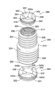
expansion ring 32
to selectively urge the upper portion 58 of the coupling sleeve 28 in the
region of top
groove 74 to resiliently deform from a non-expanded configuration 80 (shown in
FIG. 7) to
an expanded or bulging configuration 82 (shown in FIG. 14).
[0086] Turning now to FIGS. 9, 11 and 12, a detailed description of the bottom
expansion
ring 30 follows. The bottom expansion ring 30 has an upper face 84, an opposed
lower face
86 (visible in FIG. 3), a curved outer surface 88 and an inner surface 90. The
curvature of
the outer surface 88 is configured to correspond substantially to the
curvature of the bottom
groove 64.
[0087] When seen in plan view, the bottom expansion ring 30 has a generally
circular
profile defined by the curved outer surface 88, the circular profile being
interrupted by
relatively small discontinuities in the nature of ring abutment shoulders or
ridges
(generically designated by reference numeral 91) jutting outwardly from the
outer surface
88. In this embodiment, there are six (6) such abutment shoulders 91a, 91b,
912c, 91d, 91e
and 91f. As shown in FIG. 5, these ring shoulders are configured to bear
against
corresponding lower sleeve shoulders 68a, 68b, 68c, 68d, 68e and 68f formed in
the inner
surface 42 of the sleeve body 34, when the bottom expansion ring 30 is
arranged within the
bottom groove 64 and the lower portion 56 of the coupling sleeve 28 in the
region of
bottom groove 64 is in the non-expanded configuration 70. As explained in
greater detail
below, the ring abutment shoulders 91 cooperate with the inner surface 42 of
the sleeve
body 34 each other to define bottom sleeve expansion seal and locking means
92.
CA 02935561 2016-07-08
-21 -
[0088] A central cutout 93 imparts a vague annular shape to the bottom
expansion ring
30. The cutout 90 is sized large enough so as not to significantly impede the
flow of any
water that passes through the cutout 93 and the passageway 44 defined in the
coupling
sleeve 28, when the coupling assembly 20 is operatively connected to the
insert pipe 24 and
the standing drain pipe 26.
[0089] The star-like shape of the cutout 93 is defined by contoured portions,
in this case,
scalloped portions 94a, 94b, 94c, 94d, 94e and 94f (generically designated
with reference
numeral 94) formed in the inner surface 90 and disposed in a ring-like
arrangement. Each
scalloped portion 94 has a rectangular rebate generically identified with
reference numeral
95 (and more specifically, 95a, 95b, 95c, 95d, 95e and 95f) which is cut deep
into the upper
face 84 of the bottom expansion ring 30. By having each rebate 95 extend
partially into
(but not completely through) the upper face 84, a landing 96 is formed at the
location of
each rebate. The landing is configured to receive therein a portion of a key
fitting 98 and to
support the key fitting 98 so as to substantially prevent or minimize the
accidental loss of
the key fitting 98 resulting from the key fitting 98 falling through the
coupling assembly 20
and down into the standing drain pipe 26 during installation of the coupling
assembly 20.
As explained in greater detail below, when attached to a ratchet tool 100, the
key fitting 98
can be used to rotate the bottom expansion ring 30 within the coupling sleeve
28 so as to
urge the lower portion 56 of the coupling sleeve 28 in the region of bottom
groove 64 to
adopt an expanded or bulging configuration 72.
[0090] In other embodiments, the cutout 93 could be shaped differently.
[0091] During fabrication of the coupling assembly 20, the bottom expansion
ring 30 is
inserted into the bottom groove 64 where it fits snugly therein, with portions
of curved
outer surface 88 of the expansion ring 30 abutting the inner surface 42 of
sleeve body 34.
As shown in FIG. 4, the upper face 84 of the bottom expansion ring 30 is
oriented towards
the top opening 46 of the sleeve body 34 so that during installation of the
coupling
assembly 20, the key fitting 98 attached to the ratchet tool 100 can be
inserted through the
top opening 46 and be mated with the bottom expansion ring 30 (i.e. with
portions of the
key fitting 98 being received within the landings 96 formed in the scalloped
portions 94).
CA 02935561 2016-07-08
- 22 -
[0092] In this embodiment, the thickness of the bottom expansion ring 30 as
measured
between the upper face 84 and the lower face 86 is 8.5 mm. In other
embodiments, the
bottom expansion ring can be fabricated with a different thickness (i.e. a
larger or smaller
thickness). Preferably, the thickness of the bottom expansion ring measures
between 8 and
20 mm.
[0093] The bottom expansion ring 30 shown in the drawings is made of a
translucent,
hard, plastic material - polycarbonate. In other embodiments, the expansion
ring could be
fabricated from other materials selected on the basis of their strength,
rigidity and durability
characteristics. For example, the expansion ring could be made of steel or
another suitable
metal.
[0094] With reference to FIGS. 4, 7 and 9, the top expansion ring 32 is now
described.
The top expansion ring is generally similar to bottom expansion ring 30,
except that it is
sized somewhat smaller to fit snugly into the top groove 74. In like fashion
to bottom
expansion ring 30, the top expansion ring 32 has an upper face 102 (visible in
FIGS. 4 and
9), an opposed lower face 104 (visible in FIG. 3), a curved outer surface 106
and an inner
surface 108. The curvature of the outer surface 106 is configured to
correspond
substantially to the curvature of the top groove 74.
[0095] When seen in plan view, the top expansion ring 32 has a generally
circular profile
defined by the curved outer surface 106, the circular profile being
interrupted by relatively
small discontinuities in the nature of ring abutment shoulders or ridges
(generically
designated by reference numeral 110) jutting outwardly from the outer surface
106. In this
embodiment, there are six (6) such abutment shoulders 110a, 110b, 110c, 110d,
110e and
110f. As shown in FIG. 7, these ring shoulders are configured to bear against
corresponding
upper sleeve shoulders 78a, 78b, 78c, 78d, 78e and 78f formed in the inner
surface 42 of
the sleeve body 34, when the top expansion ring 32 is arranged within the top
groove 74
and the upper portion 58 of the coupling sleeve 28 in the region of top groove
74 is in the
non-expanded configuration 80. As explained in greater detail below, the ring
abutment
shoulders 110 cooperate with the inner surface 42 of the sleeve body 34 to
define top sleeve
expansion seal and locking means 111.
CA 02935561 2016-07-08
- 23 -
[0096] A central cutout 112 imparts a vague annular shape to the top expansion
ring 32.
Similar to cutout 93, the cutout 112 is sized large enough so as not to
significantly impede
the flow of any water that passes through the cutout 112 and the passageway 44
defined in
the coupling sleeve 28, when the coupling assembly 20 is operatively connected
to the
insert pipe 24 and the standing drain pipe 26.
[0097] The star-like shape of the cutout 112 is defined by contoured portions,
in this case,
scalloped portions 114a, 114b, 114c, 114d, 114e and 114f (generically
designated with
reference numeral 114) formed in the inner surface 108 and disposed in a ring-
like
arrangement. Each scalloped portion 114 has a rectangular rebate generically
identified
with reference numeral 116 (and more specifically, 116a, 116b, 116c, 116d,
116e and 116f)
which is cut deep into the upper face 102 of the top expansion ring 32. Each
116 defines a
landing 118 that is configured to receive therein a portion of a key fitting
119 and to
support the key fitting 119 so as to substantially prevent or minimize the
accidental loss of
the key fitting 119 resulting from the key fitting 119 falling through the
coupling assembly
20 and down into the standing drain pipe 26 during installation of the
coupling assembly
20. As explained in greater detail below, when attached to the ratchet tool
100, the key
fitting 119 can be used to rotate the top expansion ring 32 within the
coupling sleeve 28 so
as to urge the upper portion 58 of the coupling sleeve 28 in the region of top
groove 74 to
adopt an expanded or bulging configuration 82.
[0098] In other embodiments, the cutout 112 could be shaped differently.
[0099] During fabrication of the coupling assembly 20, the top expansion ring
32 is
inserted into the top groove 74 where it fits snugly therein, with portions of
curved outer
surface 106 of the expansion ring 32 abutting the inner surface 42 of sleeve
body 34. As
shown in FIG. 4, the upper face 102 of the top expansion ring 32 is oriented
towards the top
opening 46 of the sleeve body 34 so that during installation of the coupling
assembly 20,
the key fitting 119 attached to the ratchet tool 100 can be inserted through
the top opening
46 and be mated with the top expansion ring 32 (i.e. with portions of the key
fitting 119
being received within the landings 118 formed in the scalloped portions 114).
CA 02935561 2016-07-08
- 24 -
[00100] In this embodiment, the thickness of the top expansion ring 32 as
measured
between the upper face 102 and the lower face 104 is 8.5 mm. In other
embodiments, the
top expansion ring can be fabricated with a different thickness (i.e. a larger
or smaller
thickness). Preferably, the thickness of the bottom expansion ring measures
between 8 and
20 mm.
[00101] Preferably, the top expansion ring 32 is made of the same material to
that used for
fabricating the bottom expansion ring 30.
[00102] Referring to FIGS. 14, 15, 16 and 17, the ratchet tool 100, the key
fitting 98 and
the key fitting 119 are now described in greater detail. The ratchet tool 100
includes a
standard socket wrench or ratchet 120 and an extension rod 122 operatively
connected
thereto. The ratchet 120 has a handle portion 124 at one end, a work end
portion 126 at an
opposite end and an elongated stem portion 128 extending between the handle
portion 124
and the work end portion 126. The work end portion 126 supports a conventional
ratchet
mechanism (not shown) which terminates with a generally square male connector
(also not
shown) for mating with a generally square female socket 130 provided on the
extension rod
122. The square male connector extends generally perpendicular to the stem
portion 128.
[00103] The extension rod 122 is configured in the typical manner. At its
proximal end, it
has the generally square female socket 130 and at its distal end it terminates
with a
generally square male connector 134 (visible in FIGS. 14 and 16) for insertion
into a
generally square female socket 136 defined in the key fitting 98 or generally
square female
socket 138 defined in the key fitting 119. Preferably, the length of the
extension rod 122
measures 305 mm, which is long enough to permit the extension rod 122 to
extend all the
way through the insert pipe 24 with sufficient length left over to reach the
lower portion 56
of the coupling sleeve 28 where the bottom expansion ring 30 is situated. In
other
embodiments, a shorter or longer extension rod could be employed, as required.
[00104] With specific reference to FIG. 14, the key fitting 98 has a disc-
shaped body 140
with a central aperture formed therein which corresponds to the generally
square female
socket 136. In this embodiment, the diameter of the disc-shaped body 140
measures 50
mm. Projecting outwardly from the outer margin 142 of the disc-shaped body 140
at evenly
CA 02935561 2016-07-08
- 25 -
spaced locations, are stub arms generically identified with reference numeral
144. In this
embodiment, the disc-shaped body 140 possesses six (6) stub arms 144a, 144b,
144c, 144d,
144e and 144f. The generally rectangular stub arms 144a, 144b, 144c, 144d,
144e and 144f
constitute male portions to be received in landings 96 formed by the rebates
95a, 95b, 95c,
95d, 95e and 95f.
[00105] The key fitting 119 is generally similar to the key fitting 98 except
that it sized
slightly smaller than the key fitting 98 in order to mate with the relatively
smaller top
expansion ring 32. As shown in FIG. 16, the key fitting 119 has a disc-shaped
body 146
which resembles the disc-shaped body 140. In this regard, the body 146 also
possesses a
central aperture, but in this case, the aperture corresponds to the generally
square female
socket 138. In this embodiment, the diameter of the disc-shaped body 146
measures 45
mm. Projecting outwardly from the outer margin 148 of the disc-shaped body 146
at evenly
spaced locations, are stub arms generically identified with reference numeral
152. In this
embodiment, the disc-shaped body 152 possesses six (6) stub arms 152a, 152b,
152c, 152d,
152e and 152f. The generally rectangular stub arms 152a, 152b, 152c, 152d,
152e and 152f
constitute male portions to be received in landings 118 formed by the rebates
116a, 116b,
116c, 116d, 116e and 116f.
[00106] Having described all the various components of the coupling assembly
20, what
follows next is a description of an exemplary installation of the coupling
assembly 20 to the
insert pipe 24 of drain 22 and the standing drain pipe 26 with reference to
FIGS. 13 to 17.
Prior to installation as a preliminary step, care is taken to ensure that the
bottom expansion
ring 30 is positioned within the bottom groove 64 such that the lower portion
56 of the
sleeve body 34 in the region of the bottom groove 64 is in a non-expanded
configuration
70. Similarly, the installer verifies that the top expansion ring 32 is
positioned within the
top groove 74 such that the upper portion 58 of the sleeve body 34 in the
region of the top
groove 74 is in a non-expanded configuration 80.
[00107] Next, a waterproofing adhesive or caulking material is spread along
the outer
surface 40 of the sleeve body 34 between the threading 50 located on the top
portion 58.
Preferably, the adhesive is a cyanoacrylate adhesive. The bottom end 160 of
the insert pipe
CA 02935561 2016-07-08
- 26 -
24 is fitted onto the coupling sleeve 28 until the upper portion 58 of the
sleeve body 34 is
wholly received in the insert pipe 24 and abuts the flange 62 of the coupling
sleeve 28.
Also, in this arrangement, the outer surface 40 of the sleeve body 34 abuts
the inner surface
52 of the insert pipe 24 with the threading 50 snugly compressed up against
the inner
surface 52. Use of the adhesive assists in maintaining the upper portion 58 of
the sleeve
body 34 fixedly secured to the insert pipe with a tight seal being formed
therebetween.
While use of an adhesive has been shown to be advantageous, it need not be
used in every
application. In certain applications, the coupling assembly could be installed
to the insert
pipe without the application of adhesive.
[00108] As shown in FIG. 15, the male connector 134 of the extension rod 122
is mated
with the female socket 138 of the key fitting 119 and the ratchet tool 100
outfitted with the
key fitting 119 carried on the extension rod 122, is inserted through the top
opening 46 of
the sleeve body 34. The stub arms 152a, 152b, 152c, 152d, 152e and 152f
radiating from
the disc-shaped boy 146 are received within the landings 118 such that the key
fitting 119
and the top expansion ring 32 are now fixed to each other for rotation. .
Alternatively, the
key fitting 119 could be manually inserted into the sleeve body and positioned
into the
landings formed in the top expansion ring and the ratchet tool could then
fitted through the
top opening to mate the extension arm with the key fitting.
[00109] Thereafter, the installer grasps the handle portion 124 of the ratchet
tool 100 and
uses the tool to urge the top expansion ring 32 to rotate within the top
groove 74. As the
top expansion ring 32 rotates, each ring abutment shoulders 110 is urged to
travel within a
curved rebate 76 and is displaced from the top sleeve shoulder 78 with which
it was
associated when the upper portion 58 of the sleeve body 34 in the region of
the top groove
74 was in the non-expanded configuration 80. The rigid outer surface 106 of
the top
expansion ring 32 (more specifically, the ring abutment shoulders 91a, 91b,
91c, 91d, 91e
and 911) pushes against the inner surface 42 of the sleeve body 34 in an area
where the
sleeve body 34 has increased thickness, thereby causing the upper portion 58
of the sleeve
body 34 in the region of the top groove 74 to resiliently deform and adopt the
expanded or
bulging configuration 82 shown in FIG. 16. Expansion of the sleeve body 34 in
the region
of the top groove 74 tends to "lock" or tightly hold the coupling sleeve 28 in
place against
CA 02935561 2016-07-08
- 27 -
the inner surface 52 of the insert pipe 24, and create a tight seal between
the coupling
sleeve 28 and the insert pipe 24. Care should be taken not to rotate the top
expansion ring
too much, otherwise the ring abutment shoulders 110 may be moved to abut
against top
sleeve shoulders 78 and the sleeve body 34 in the region of the top groove 74
may revert
back to the non-expanded configuration 80.
[00110] The key fitting 119 is then detached from the top expansion ring 32
and the
ratchet tool 100 with the key fitting 119 mounted thereto is pulled out from
the sleeve body
172.
[00111] With the insert pipe securely fixed to the coupling assembly 20, the
coupling
assembly 20 can now be connected to the standing drain pipe. Optionally,
waterproofing
adhesive may be spread along the outer surface 40 of the sleeve body 34
between the
threading 50 located on the lower portion 56. The coupling assembly 20 with
the insert pipe
24 attached thereto is then introduced into the space defined between the roof
structure 25
and the support structure 27 through opening 154. The sleeve body 34 is
inserted into the
top end 156 of the standing drain pipe 26 until the lower portion 56 is wholly
received in
the standing drain pipe 26, and the top circumferential flange 162 of the
insert pipe 24 rests
the roof structure 25. In this arrangement, the outer surface 40 of the sleeve
body 34 abuts
the inner surface 54 of the standing drain pipe 26 with the threading 50
snugly compressed
up against the inner surface 54. Where adhesive is used, the lower portion 56
of the sleeve
body 34 can be permanently secured to the standing drain pipe 26 with a tight
seal being
formed therebetween. While use of the adhesive has been shown to be
advantageous, it is
optional and need not be used in every application. In certain applications,
the coupling
assembly could be installed to the standing drain pipe without the application
of adhesive.
[00112] With the coupling assembly 20 thus arranged, only a small gap G
remains
between the standing drain pipe 26 and the insert pipe 24, the gap G being
bridged by the
narrow intermediate transition portion 60 of the sleeve body 34.
[00113] As shown in FIG. 13, the male connector 134 of the extension rod 122
is mated
with the female socket 136 of the key fitting 98 and the ratchet tool 100
outfitted with the
key fitting 98 carried on the extension rod 122, is inserted through the top
opening 46 of the
CA 02935561 2016-07-08
- 28 -
sleeve body 34. The stub arms 114a, 114b, 114c. 114d, 114e and 114f radiating
from the
disc-shaped boy 140 are received within the landings 96 such that the key
fitting 98 and the
bottom expansion ring 32 are now fixed to each other for rotation.
Alternatively, the key
fitting 98 could be manually inserted into the sleeve body and positioned into
the landings
formed in the bottom expansion ring and the ratchet tool could then fitted
through the top
opening to mate the extension arm with the key fitting.
[00114] Thereafter, the installer grasps the handle portion 124 of the ratchet
tool 100 and
uses the tool to urge the bottom expansion ring 30 to rotate in a clockwise
direction within
the bottom groove 64. As the bottom expansion ring 30 rotates, each ring
abutment
shoulders 91 is urged to travel within a curved rebate 66 and is displaced
from the lower
sleeve shoulder 68 with which it was associated when the lower portion 56 of
the sleeve
body 34 in the region of the bottom groove 64 was in the non-expanded
configuration 70.
The rigid outer surface 88 of the bottom expansion ring 30 pushes against the
inner surface
42 of the sleeve body 34 in an area where the sleeve body 34 has increased
thickness,
thereby causing the lower portion 56 of the sleeve body 34 in the region of
the bottom
groove 64 to resiliently defonn and adopt the expanded or bulging
configuration 72 shown
in FIG. 14. Expansion of the sleeve body 34 in the region of the bottom groove
64 tends to
"lock" or tightly hold the coupling sleeve 28 in place against the inner
surface 54 of the
standing drain pipe and create a tight seal between the coupling sleeve 28 and
the standing
drain pipe 26. Care should be taken not to rotate the bottom expansion ring
too much,
otherwise the ring abutment shoulders 91 may be moved to abut against lower
sleeve
shoulders 68 and the sleeve body 34 in the region of the bottom groove 64 may
revert back
to the non-expanded configuration 70.
[00115] The key fitting 98 is then detached from the bottom expansion ring 30
and the
ratchet tool 100 with the key fitting 98 mounted thereto is pulled out from
the sleeve body
172.
[00116] With the coupling assembly 20 now secured to both the insert pipe 24
and the
standing drain pipe 24, the installation is completed by affixing a
hemispherical vented
drain portion to the top flange 162 of the insert pipe 24 (see FIG. 17).
CA 02935561 2016-07-08
- 29 -
[00117] It will thus be appreciated that installation of the coupling assembly
20 within the
insert pipe 24 and the standing drain pipe 26 can be performed relatively
quickly and easily
and without the use of expensive customized tools. In this regard, the use of
a standard
ratchet tool 100 is most advantageous in that it is a popular tool which can
be found in the
toolboxes of most workmen. Moreover, it can be sourced from any local hardware
store, if
necessary, thereby obviating the inconvenience, delay and cost which are
typically incurred
when a custom tool can only be purchased from a small number of specialized
plumbing or
roofing supply outlets. Moreover, the key fittings 98 and 119 are relatively
cheap to
manufacture, compact and portable, such that an installer could easily carry
spares of such
key fittings in his/her toolbox to various job sites.
[00118] Moreover, this installation method offers the additional advantage of
allowing the
installer to tighten or "lock" the coupling assembly in place to each of the
standing pipe
drain and the insert pipe, separately. This tends to be desirable because it
allows the
installer to connect the insert pipe to the standing drain pipe with the
coupling sleeve
already attached to the insert pipe, which tends to facilitate installation.
Another advantage
is that the once the coupling sleeve is fully attached (or locked) to the
insert pipe roof it
tends not to dislodge from the insert pipe once you place it into the drain
pipe. This tends to
substantially reduce the risk of the coupling assembly falling into the
standing drain pipe.
[00119] If required for maintenance purposes or other purposes, the coupling
assembly can
be disconnected from the standing drain pipe or the insert pipe by simply
rotating the
bottom expansion ring or the top expansion ring so that the region of the
sleeve body in the
area of the bottom groove or top groove is no longer deformed and adopts the
non-
expanded configuration.
[00120] In the preferred embodiment shown in FIGS. 5 and 7, the coupling
sleeve 28 is
formed with six (6) bottom sleeve shoulders 68 disposed about the bottom
groove 64 and
six (6) top sleeve abutment shoulders 78 located around the top groove 74.
Correspondingly, the bottom expansion ring 30 is formed with six (6) ring
abutment
shoulders 91 and the top expansion ring 30 is configured with six (6) ring
abutment
shoulders 110. This need not be the case in every application. In other
embodiments, the
CA 02935561 2016-07-08
- 30 -
top sleeve expansion seal and locking means could use a different number of
sleeve
abutment shoulders and ring abutment shoulders than that employed for the
bottom sleeve
expansion seal and locking means. Alternatively, the top and bottom sleeve
expansion seal
and locking means could use the same number of sleeve abutment shoulders and
ring
abutment shoulders, which number can be greater or lesser than six (6), but
preferably at
least two (2). Where two (2) sleeve abutment shoulders and two (2) ring
abutment
shoulders are employed, it is recommended to have the sleeve abutment
shoulders
positioned at 180 degrees from each other, and two (2) ring abutment shoulders
positioned
at 180 degrees from each other.
[00121] FIGS. 18 to 25 show an alternative embodiment of a coupling assembly
that uses
an arrangement of four (4) sleeve abutment shoulders configured in each of the
top and
bottom portions of the sleeve body, and four (4) ring abutment shoulders
formed in each of
the top and bottom expansion rings. In the figures, the alternative coupling
assembly is
designated generally with reference numeral 170. The coupling assembly 170
resembles
very closely the coupling assembly 20 in that it too includes a flexible
coupling sleeve 172,
a rigid bottom expansion ring 174 and a rigid top expansion ring 176. The
coupling sleeve
172 is similar to the coupling sleeve 28 in all material respects, except for
the configuration
of the top and bottom grooves and more specifically, the number of abutment
shoulders that
each groove possesses. The coupling sleeve 172 is made of an elastomeric
material and has
a generally tubular sleeve body 180 which extends between a top end 182 and a
bottom end
184 (see FIGS. 18 and 19).
[00122] The sleeve body 180 has an outer surface 186 and an inner surface 188
which
defines a longitudinal passageway 190 that communicates with a top opening 192
and a
bottom opening 194. Disposed helically along the outer surface 186 of the
sleeve body 180
between the top and bottom ends 182 and 184 and formed thereon, is raised
helical
threading 196.
[00123] As shown in FIGS. 18 and 19, the sleeve body 180 further includes a
lower
portion 198, an upper portion 200 and an intermediate transition portion 202
joining the
lower portion 198 to the upper portion 200. The intermediate portion 202 is
relatively
CA 02935561 2016-07-08
-31 -
narrow and is formed roughly midway between the upper and lower portions 198
and 200.
In the region of the intermediate portion 202, the sleeve body 180 tapers
gently in the
direction of the upper portion 200 before terminating with a very short flange
204 that
connects to the upper portion 200.
[00124] As found in the sleeve body 34, there is a first station in the nature
of a
circumferential bottom groove 206 defined in the inner surface 188 of the
sleeve body 180.
The bottom groove 206 is configured to accommodate therein the bottom
expansion ring
174. In like fashion to the bottom groove 64, the bottom groove 206 has a
generally
arcuate profile. As best shown in FIG. 21, the bottom groove 206 is formed
with a series of
discrete curved rebate regions generically designated with reference numeral
208, disposed
in a ring-like arrangement. In this embodiment, there are four (4) discrete
curved rebate
regions 208a, 208b, 208c and 208d circumferentially disposed one adjacent the
other. Each
rebate region 208 is bound on either side by a lower sleeve abutment shoulder
or ridge,
(generically designated by reference numeral 210) that is formed into the
inner surface 188
of the sleeve body 180 and juts inwardly into the passageway 190.
[00125] More specifically, curved rebate region 208a is bound by shoulder 210a
and
shoulder 210b; rebate region 208b is bound by shoulder 210b and shoulder 210c;
rebate
region 208c is bound by shoulder 210c and shoulder 210d; rebate region 208d is
bound by
shoulder 210d and shoulder 210a. In this embodiment, because there are fewer
curved
rebate regions than in the embodiment shown in FIG. 6, each rebate region 208
occupies a
larger part of the circumference of bottom groove 206.
[00126] As was the case for the curved rebate regions 66, the thickness of the
sleeve body
180 in a curved rebate region 208 varies between adjacent shoulders 210. For
example, in
curved rebate region 208a the sleeve body 180 is thinnest just beyond the
shoulder 210a
(see thickness T5 in FIG. 24). The thickness of the sleeve body 180 increases
as one follows
the curve of the rebate region 208a and moves further away from shoulder 210a,
with the
sleeve body 180 having its greatest thickness at shoulder 210b (see thickness
T6 in FIG. 24).
Preferably, the increase in thickness is gradual. It will thus be understood
that the locations
of the shoulders 210 correspond to areas of increased thickness in the sleeve
body 180. The
CA 02935561 2016-07-08
- 32 -
curved rebate regions 208 and the shoulders 210 are configured to
cooperatively engage
portions of the bottom expansion ring 174 to selectively urge the lower
portion 198 of the
coupling sleeve 170 in the region of bottom groove 206 to resiliently deform
from a non-
expanded configuration 212 (shown in FIG. 20) to an expanded or bulging
configuration
214 (shown in FIG. 22).
[00127] A second station in the nature of a circumferential top groove 216 is
defined in the
inner surface 188 of the sleeve body 180, a short distance away from the top
opening 192.
The top groove 216 is configured to receive therein the top expansion ring
176. The top
groove 216 is generally similar to bottom groove 206, except that it is sized
somewhat
smaller on account of the smaller diameter of the sleeve body 180 in that
area. In like
fashion to bottom groove 206, the top groove 216 has a generally arcuate
profile and is
formed with a series of discrete curved rebate regions generically designated
with reference
numeral 218, disposed in a ring-like arrangement. However, as shown in FIG.
24, in this
embodiment, there are four (4) discrete curved rebate regions 218a, 218b, 218c
and 218d
(generically, identified with reference numeral 218) circumferentially
disposed one
adjacent the other.
[00128] Each rebate region 218 is bound on either side by an upper shoulder
abutment
shoulder or ridge, (generically designated by reference numeral 220) that is
formed into the
inner surface 188 of the sleeve body 180 and juts inwardly into the passageway
190. For
example, curved rebate region 218a is bound by shoulder 220a and shoulder
220b. The
thickness of the sleeve body 180 in a curved rebate region 218 varies between
adjacent
shoulders 220 in the same manner as described above in the regards to a curved
rebate
region 208, such that no further description is required. It will be
appreciated that the
curved rebate regions 208 and the shoulders 220 are configured to
cooperatively engage
portions of the top expansion ring 176 to selectively urge the upper portion
200 of the
coupling sleeve 180 in the region of top groove 216 to resiliently deform from
a non-
expanded configuration 222 (as shown in FIG. 23) to an expanded or bulging
configuration
224 (as shown in FIG. 25).
CA 02935561 2016-07-08
- 33 -
[00129] Turning now to FIGS. 19 and 20, a detailed description of the bottom
expansion
ring 174 follows. The bottom expansion ring 174 closely resembles the bottom
expansion
ring 30 in that it too has an upper face 225, an opposed lower face (not
shown), a curved
outer surface 226 and an inner surface 228. The curvature of the outer surface
226 is
configured to correspond substantially to the curvature of the bottom groove
206.
[00130] When seen in plan view, the bottom expansion ring 174 has a generally
circular
profile defined by the curved outer surface 226, the circular profile being
interrupted by
relatively small discontinuities in the nature of ring abutment shoulders or
ridges
(generically designated by reference numeral 230) jutting outwardly from the
outer surface
226. However, in this embodiment, there are only four (4) such abutment
shoulders 230a,
230b, 230c, and 230d. As shown in FIG. 19, these ring shoulders are configured
to bear
against corresponding lower sleeve shoulders 210a, 210b, 210c and 210d formed
in the
inner surface 188 of the sleeve body 180, when the bottom expansion ring 174
is arranged
within the bottom groove 206 and the lower portion 198 of the coupling sleeve
172 in the
region of bottom groove 206 is in the non-expanded configuration 212.
[00131] A central cutout 232 imparts a vague annular shape to the bottom
expansion ring
174. The cutout 232 is sized large enough so as not to significantly impede
the flow of any
water that passes through the cutout 232 and the passageway 190 defined in the
coupling
sleeve 172, when the coupling assembly 170 is operatively connected to the
insert pipe 24
and the standing drain pipe 26.
[00132] Unlike cutout 93 defined in the bottom expansion ring 30 which has a
star-like
shape, the shape of the cutout 232 resembles that of a quatrefoil and is
defined by four
contoured portions, in this case, scalloped portions 234a, 234b, 234c and 234d
(generically
designated with reference numeral 234) formed in the inner surface 228 and
disposed in a
ring-like arrangement. Each scalloped portion 234 has a rectangular rebate
generically
identified with reference numeral 236 (and more specifically, 236a, 236b, 236c
and 236d)
which is cut deep into the upper face 222 of the bottom expansion ring 174.
Each rebate
236 defines a landing 238 to receive therein a portion of a key fitting 240
which, when to
the ratchet tool 100, can be used to rotate the bottom expansion ring 174
within the
CA 02935561 2016-07-08
- 34 -
coupling sleeve 172 so as to urge the lower portion 198 of the coupling sleeve
172 in the
region of bottom groove 206 to adopt an expanded or bulging configuration 214.
[00133] During fabrication of the coupling assembly 170, the bottom expansion
ring 174 is
inserted into the bottom groove 206 where it fits snugly therein, with
portions of curved
outer surface 226 of the expansion ring 174 abutting the inner surface 186 of
sleeve body
180, and the upper face 225 of the expansion ring 174 oriented towards the top
opening 192
of the sleeve body 180.
[00134] The bottom expansion ring 174 is sized similar to the bottom expansion
ring 30
and can be made of the same or similar materials.
[00135] With reference to FIGS. 19, 23 and 25, the top expansion ring 176 is
now
described. The top expansion ring is generally similar to bottom expansion
ring 174,
except that it is sized somewhat smaller to fit snugly into the top groove
216. The top
expansion ring 176 closely resembles the top expansion ring 32 in that it too
has an upper
face 242 (visible in FIGS. 19), an opposed lower face 244, a curved outer
surface 246 and
an inner surface 248. The curvature of the outer surface 246 is configured to
correspond
substantially to the curvature of the top groove 216.
[00136] When seen in plan view, the top expansion ring 176 has a generally
circular
profile defined by the curved outer surface 246, the circular profile being
interrupted by
relatively small discontinuities in the nature of ring abutment shoulders or
ridges
(generically designated by reference numeral 250) jutting outwardly from the
outer surface
246. In this embodiment, there are four (4) such abutment shoulders 250a,
250b, 250c, and
250d. As shown in FIG. 23, these ring shoulders are configured to bear against
corresponding upper sleeve shoulders 220a, 220b, 220c and 220d formed in the
inner
surface 188 of the sleeve body 172, when the top expansion ring 174 is
arranged within the
top groove 216 and the upper portion 200 of the coupling sleeve 170 in the
region of top
groove 216 is in the non-expanded configuration 222.
[00137] A central cutout 252 imparts a vague annular shape to the top
expansion ring 176.
The cutout 252 is sized large enough so as not to significantly impede the
flow of any water
CA 02935561 2016-07-08
- 35 -
that passes through the cutout 252 and the passageway 190 defined in the
coupling sleeve
172, when the coupling assembly 170 is operatively connected to the insert
pipe 24 and the
standing drain pipe 26.
[00138] In like fashion to the cutout 232, the cutout 252 is in the shape of a
quatrefoil and
is defined by four contoured portions, in this case, scalloped portions 254a,
254b, 254c and
254d (generically designated with reference numeral 254) formed in the inner
surface 248
and disposed in a ring-like arrangement. Each scalloped portion 254 has a
rectangular
rebate generically identified with reference numeral 256 (and more
specifically, 256a,
256b, 256c and 256d) which is cut deep into the upper face 242 of the top
expansion ring
176. Each rebate 256 defines a landing 258 to receive therein a portion of a
key fitting 260
which, when to the ratchet tool 100, can be used to rotate the top expansion
ring 176 within
the coupling sleeve 172 so as to urge the upper portion 200 of the coupling
sleeve 172 in
the region of top groove 216 to adopt an expanded or bulging configuration
224.
[00139] During fabrication of the coupling assembly 170, the top expansion
ring 176 is
inserted into the top groove 216 where it fits snugly therein, with portions
of curved outer
surface 226 of the expansion ring 176 abutting the inner surface 246 of sleeve
body 180,
and the upper face 242 of the expansion ring 176 oriented towards the top
opening 192 of
the sleeve body 180.
[00140] The top expansion ring 176 is sized similar to the top expansion ring
32 and can
be made of the same or similar materials.
[00141] Referring to FIGS. 23 and 25, the key fitting 240 and the key fitting
260 are now
described in greater detail. The key fitting 240 has a disc-shaped body 262
which
resembles the disc-shaped body 140 of the key fitting 98. It has a central
aperture formed
therein which defines a generally square female socket 264 and diameter that
is similar in
size to that of the disc-shaped body 140. However, in contrast to the disc-
shaped 140, the
body 262 only has four stub arms generically identified with reference numeral
266 (more
specifically, stub arms 266a, 266b, 266c and 266d) which project outwardly
from the outer
margin 268 of the disc-shaped body 262 at evenly spaced locations. The
generally
CA 02935561 2016-07-08
- 36 -
rectangular stub arms 266a, 266b, 266c and 266d constitute male portions to be
received in
landings 238 formed by the rebates 236a, 236b, 236c and 236d.
[00142] The key fitting 260 is generally similar to the key fitting 119 in
that it too is sized
to mate with the top expansion ring 176. As shown in FIG. 25, the key fitting
260 has a
disc-shaped body 270 which resembles the disc-shaped body 146. The key fitting
260
possesses a central aperture that defines a generally square female socket
272. However,
unlike the key fitting 119, the key fitting 260 only has four stub arms
generically identified
with reference numeral 274 (more specifically, stub arms 274a, 274b, 274c and
274d)
which project outwardly from the outer margin 276 of the disc-shaped body 270
at evenly
spaced locations. The generally rectangular stub arms 274a, 274b, 274c and
274d constitute
male portions to be received in landings 258 formed by the rebates 256a, 256b,
256c and
256d.
[00143] The installation of the installation of the coupling assembly 170 to
the insert pipe
24 of drain 22 and the standing drain pipe 26 is performed in a manner similar
to that
described earlier in connection with coupling assembly 20 such that no further
description
is required other than a brief description of how each of the expansion rings
30 and 32 are
displaced within their respective groove 206 and 216 so as to cause the sleeve
body 172 to
bulge outwardly.
[00144] Referring to FIG. 25, the key fitting 260 is fitted onto the top
expansion ring 176
with its stub arms 274a, 274b, 274c and 274d received within the landings 258.
Using the
ratchet tool 100, the key fitting 260 and the top expansion ring 176 are urged
to rotate. Care
is taken not to over-rotate the top expansion ring 176. This rotation causes
each ring
abutment shoulders 250 to travel within a curved rebate 218 and to move away
from the
upper sleeve shoulder 220 with which it was associated when the upper portion
200 of the
sleeve body 172 in the region of the top groove 216 was in the non-expanded
configuration
222. The rigid outer surface 246 of the top expansion ring 176 pushes against
the inner
surface 188 of the sleeve body 172 in an area where the sleeve body 172 has
increased
thickness, thereby causing the upper portion 200 of the sleeve body 172 in the
region of the
bottom groove 216 to resiliently deform and adopt the expanded or bulging
configuration
CA 02935561 2016-07-08
- 37 -
224. Expansion of the sleeve body 172 in the region of the top groove 216
tends to "lock"
or tightly hold the coupling sleeve 170 in place against the inner surface 52
of the insert
pipe 24 and create a tight seal between the coupling sleeve 170 and the insert
pipe 24. Care
should be taken not to rotate the bottom expansion ring 174 too much,
otherwise the ring
abutment shoulders 230 may be moved to abut against lower sleeve shoulders 210
and the
sleeve body 172 in the region of the bottom groove 206 may revert back to the
non-
expanded configuration 212.
[00145] With reference to FIG. 22, expansion of the sleeve body 172 in the
area of the
bottom groove 206 takes place in a very similar fashion. The key fitting 240
is fitted onto
the bottom expansion ring 174 with its stub arms 266a, 266b, 266c and 266d
received
within the landings 118. Using the ratchet tool 100, the key fitting 240 and
the bottom
expansion ring 174 are urged to rotate. Care is taken not to over-rotate the
bottom
expansion ring 174. This rotation causes each ring abutment shoulders 230 to
travel within
a curved rebate 208 and to move away from the lower sleeve shoulder 210 with
which it
was associated when the lower portion 198 of the sleeve body 172 in the region
of the
bottom groove 206 was in the non-expanded configuration 212. The rigid outer
surface
226 of the bottom expansion ring 174 pushes against the inner surface 188 of
the sleeve
body 172 in an area where the sleeve body 172 has increased thickness, thereby
causing the
lower portion 198 of the sleeve body 172 in the region of the bottom groove
206 to
resiliently deform and adopt the expanded or bulging configuration 214.
Expansion of the
sleeve body 172 in the region of the bottom groove 206 tends to tightly "lock"
or hold the
coupling sleeve 170 against the inner surface 54 of the standing drain pipe 26
and create a
tight seal between the coupling sleeve 170 and the standing drain pipe 26.
[00146] Other modifications are possible. For example, in other embodiments,
the sleeve
abutment shoulders and the ring abutment shoulders could be configured
differently. For
example, the shoulders could be configured as saw teeth, rounded bumps, nubs,
or other
shaped projections or structures.
[00147] In alternative embodiments, the configuration and arrangement of stub
arms in the
key fittings and the rebates or landings in the expansion rings could be
different.
CA 02935561 2016-07-08
- 38 -
[00148] The coupling assemblies described above could be provided in a kit
which would
include a coupling sleeve, a bottom expansion, a top expansion ring, a first
key fitting
adapted to engage the bottom expansion ring and a second key fitting adapted
to engage the
top expansion ring. Each kit could be designed for use with a standing drain
pipe of a
predetermined size and a correspondingly sized drain. In an alternative
embodiment, it
may be possible for a kit to be provided with only a single key fitting
suitable to engage
both the top expansion ring and the bottom expansion ring. In a further
alternative, the kit
could include a coupling sleeve, a bottom expansion and a top expansion ring,
with the first
and second key fittings being provided separately.
[00149] In the embodiments described above, sleeve expansion seal and locking
means are
defined by ring abutment shoulders of an expansion ring cooperating with the
inner surface
of the sleeve body. In other embodiments, the sleeve expansion seal and
locking means can
be formed by a different structural interaction between the expansion rings
and the sleeve
body. For example, in an alternative embodiment, the expansion rings could be
configured
with threading about their outer circumferential surface for threaded
engagement with
corresponding threading running along the inner surface of the sleeve body.
The interior
passageway of the sleeve body could be provided with an hourglass-like taper
(i.e. tapering
from both the upper and lower portions of the sleeve body toward the middle).
Configured
in this manner, when the top and bottom expansion rings are urged to advance
towards the
middle of the sleeve body as they travel along the threading formed in the
inner surface of
the sleeve body, the expansion rings would push out against the interior
surface of the
sleeve body in the area where the wall thickness is increased due to the
taper, thereby
causing compression of the sleeve body between the top expansion ring 284 and
the insert
pipe, and the bottom expansion ring 286 and the standing drain pipe. An
example of such
alternative embodiment is described in greater detail below with reference to
FIGS. 26 to
41.
[00150] FIG. 31 shows a coupling assembly 280 that includes a flexible
coupling sleeve
282, a rigid bottom expansion ring 284 and a rigid top expansion ring 286. The
coupling
sleeve 282 is generally similar to the sleeve coupling 28 in that the sleeve
282 is also made
of a fluid impermeable, elastomeric material (preferably, ethylene propylene
diene
CA 02935561 2016-07-08
- 39 -
monomer (EPDM) rubber) and also has a generally tubular sleeve body 288 which
extends
between a top end 290 and a bottom end 292 (see FIGS. 27 and 30).
[00151] With reference to FIG. 32, the sleeve body 288 can be seen to have an
outer
surface 294 and an inner surface 296 which defines a longitudinal passageway
298 that
communicates with a top opening 300 and a bottom opening 302. Disposed
helically along
the outer surface 294 of the sleeve body 288 between the top and bottom ends
290 and 292
and formed thereon, is raised threading 304, similar to threading 50 (shown in
FIG. 2).
[00152] As shown in FIG. 41, the sleeve body 288 further includes a lower
portion 306
provided with an outer diameter DL (measured about the outer surface 294, but
excluding
the threading 304), an upper portion 308 provided with a relatively smaller
outer diameter
Du (also measured about the outer surface 294, but excluding the threading
304) and an
intermediate transition portion 310 joining the lower portion 306 to the upper
portion 308.
The outer diameter DL is sized to be smaller than the internal diameter DDp of
the standing
drain pipe 26 such that the lower portion 306 can fit snugly within the
standing drain pipe
26, when the coupling sleeve 280 is inserted therein. Similarly, the outer
diameter Du of
the upper portion 308 is sized to be smaller than the internal diameter Dip of
the insert pipe
24 to allow the upper portion 58 to fit snugly within the insert pipe 24, when
the coupling
sleeve 280 is connected to the drain 22. It should be noted that in this
arrangement, the
internal diameter D1p of the insert pipe 24 is relatively smaller than the
internal diameter
DDp of the standing drain pipe 26. In this embodiment, DL, Du, DDp, and D1p of
the sleeve
body 288 have the same dimensions as the same as DL, Du, DDp, and D1p of
sleeve body 28.
[00153] The intermediate portion 310 is relatively narrow and is formed
roughly midway
between the upper and lower portions 308 and 306. In the region of the
intermediate
portion 310, the sleeve body 288 tapers in the direction of the upper portion
308.
[00154] Referring specifically to FIG. 32, one can see two distinct sets of
tapered, helical
female threading running along the inner surface 296 of the sleeve body 288 -
upper female
threading 314 which tapers from the upper end 290 toward the intermediate
portion 310,
and lower female threading 316 which tapers from the lower end 292 toward the
intermediate portion 310. As explained in greater detail below, the upper
female threading
CA 02935561 2016-07-08
- 40 -
314 is configured to match male threading 318 disposed on the outer surface
320 of the top
expansion ring 286, while the lower female threading 316 is configured to
match male
threading 322 on the outer surface 324 of the bottom expansion ring 284.
[00155] Due to the taper in threading 314 and 316, the internal passageway 298
can be
seen to narrow from both ends in an hourglass fashion. Correspondingly, the
thickness of
the sleeve body wall 326 increases from each of the top and bottom ends 290
and 292
towards the middle of the sleeve body 288 (i.e. the intermediate portion 310).
A shoulder
328 formed in the sleeve body 288 projects into the internal passageway 298,
thereby
creating a discontinuity (or hard transition) in the passageway 298 and a
clear demarcation
between the upper female threading 314 and the lower female threading 316.
[00156] Turning now to FIGS. 31, 33 and 34, a detailed description of the
bottom
expansion ring 284 follows. The bottom expansion ring 284 has an upper face
330, an
opposed lower face 332, the curved outer surface 324 and a curved inner
surface 336.
Helical male threading 322 runs along the curved outer surface 324.
[00157] A central circular cutout 338 imparts an annular shape to the bottom
expansion
ring 284. The cutout 338 is sized large enough so as not to significantly
impede the flow of
any water that passes through the cutout 338 and the passageway 298 defined in
the
coupling sleeve 288, when the coupling assembly 280 is operatively connected
to the insert
pipe 24 and the standing drain pipe 26.
[00158] Cut deep into the upper face 330 of the bottom expansion ring 284
along the edge
of the cutout 338, is a plurality of rectangular rebates 340 (more
specifically, four (4)
evenly-spaced rebates 340a, 340b, 340c and 340d). By having each rebate 340
extend
partially into (but not completely through) the upper face 330, a landing 342
is formed at
the location of each rebate 340. The landing 342 is configured to receive
therein a portion
of a key fitting 344 and to support the key fitting 344 so as to substantially
prevent or
minimize the accidental loss of the key fitting 344 resulting from the key
fitting 344 falling
through the coupling assembly 280 and down into the standing drain pipe 26
during
installation of the coupling assembly 280. As explained in greater detail
below, when
attached to the ratchet tool 100, the key fitting 344 can be used to advance
the bottom
CA 02935561 2016-07-08
-41 -
expansion ring 284 along threading 316 toward the intermediate portion 310
within the
coupling sleeve 280 so as to urge the sleeve body wall 326 in that region to
adopt an
expanded or bulging configuration 346 (shown in FIG. 41).
[00159] The bottom expansion ring 284 is sized to fit into the lower portion
306 of the
sleeve body 288. During installation of the coupling assembly 280, the upper
face 330 of
the bottom expansion ring 284 is oriented towards the top opening 300 of the
sleeve body
288 so that the key fitting 344 attached to the ratchet tool 100 can be
inserted through the
top opening 300 and be mated with the bottom expansion ring 284 (i.e. with
portions of the
key fitting 344 being received within the landings 342).
[00160] The thickness of the bottom expansion ring 284 as measured between the
upper
face 330 and the lower face 332 will vary depending on the size of the
coupling sleeve and
the standing drain pipe.
[00161] The bottom expansion ring 284 shown in the drawings is made of a
translucent,
hard, plastic material - polycarbonate. In other embodiments, the expansion
ring could be
fabricated from other materials selected on the basis of their strength,
rigidity and durability
characteristics. For example, the expansion ring could be made of steel or
another suitable
metal.
[00162] With reference to FIGS. 31, 35 and 36, the top expansion ring 286 is
now
described. The top expansion ring is generally similar to bottom expansion
ring 284,
except that it is sized somewhat smaller to fit into the upper portion 308 of
the sleeve body
288. In like fashion to bottom expansion ring 284, the top expansion ring 286
has an upper
face 348, an opposed lower face 350, the curved outer surface 320 and a curved
inner
surface 352. Helical male threading 318 runs along the curved outer surface
320.
[00163] A central circular cutout 354 imparts an annular shape to the top
expansion ring
286. The cutout 354 is sized large enough so as not to significantly impede
the flow of any
water that passes through the cutout 354 and the passageway 298 defined in the
coupling
sleeve 288, when the coupling assembly 280 is operatively connected to the
insert pipe 24
and the standing drain pipe 26.
CA 02935561 2016-07-08
- 42 -
[00164] Cut deep into the lower face 350 of the top expansion ring 286 along
the edge of
the cutout 354, is a plurality of rectangular rebates 356 (more specifically,
four (4) evenly-
spaced rebates 356a, 356b, 356c and 356d). By having each rebate 356 extend
partially
into (but not completely through) the lower face 350, a landing 358 is formed
at the
location of each rebate 356. The landing 356 is configured to receive therein
a portion of
the key fitting 344. As explained in greater detail below, when attached to
the ratchet tool
100, the key fitting 344 can be used to advance the top expansion ring 286
toward the
intermediate portion 310 within the coupling sleeve 280 so as to urge the
sleeve body wall
326 in that region to adopt an expanded or bulging configuration 360.
[00165] Full-length grooves 362 are also formed along the edge of the cutout
354 at
locations circumferentially staggered away from each landing 358. The grooves
362 run
from the upper face 348 to the lower face 350 of the top expansion ring 286.
In this
embodiment, there are four grooves 362 (the number of grooves matching the
number of
stub arms of the key fitting 344). Each groove 362 is shaped so as to allow a
portion of the
key fitting 344 to pass therethrough. As will be explained in greater detail
below, this
feature allows the same key fitting 344 to be used with both the bottom
expansion ring 284
and the top expansion ring 286.
[00166] The top expansion ring 286 is sized to fit into the upper portion 308
of the sleeve
body 288. During installation of the coupling assembly 280, the lower face 350
of the top
expansion ring 286 is oriented towards the bottom opening 302 of the sleeve
body 288 so
that the key fitting 344 attached to the ratchet tool 100 can be inserted
through the bottom
302 and be mated with the top expansion ring 286 (i.e. with portions of the
key fitting 344
being received within the landings 358).
[00167] The thickness of the top expansion ring 284 as measured between the
upper face
348 and the lower face 350 will vary depending on the size of the coupling
sleeve and the
insert pipe.
[00168] Referring to FIGS. 38 and 40, the key fitting 344 is now described in
greater
detail. The key fitting 344 has a disc-shaped body 370 with a central aperture
formed
therein which defines a generally square female socket 372 configured to mate
with the
CA 02935561 2016-07-08
- 43 -
generally square male connector (not shown) of the ratchet tool 110. The
diameter of the
disc-shaped body 370 will be sized appropriately to mate with both the top and
bottom
expansion rings 286 and 284. Projecting outwardly from the outer margin 374 of
the disc-
shaped body 370 at evenly spaced locations, are stub arms generically
identified with
reference numeral 376. In this embodiment, the disc-shaped body 140 possesses
four (4)
stub arms 376a, 376b, 376c and 376d. In other embodiments, the disc-shaped
body could
be provided with a different number of stub arms and correspondingly, the top
and bottom
expansion rings would be adapted with a matching number of landings. The
generally
rectangular stub arms 376a, 376b, 376c and 376d constitute male portions to be
received in
landings 342 formed by the rebates 340a, 340b, 340c and 340d, and in landings
358 formed
by the rebates 356a, 356b, 356c and 356d. Advantageously, the length of the
stub arms 376
is appropriately sized to allow it to engage both top and bottom expansion
rings 286 and
284. This reduces the hardware required for installation of the coupling
assembly 280.
[00169] Having described all the various components of the coupling assembly
280, what
follows next is a description of an exemplary installation of the coupling
assembly 280 to
the insert pipe 24 of drain 22 and the standing drain pipe 26 with reference
to FIGS. 37 to
41. Prior to installation as a preliminary step, care is taken to ensure that
the bottom
expansion ring 284 is in threaded engagement with the sleeve body 288 and the
bottom
expansion ring 284 is advanced into the lower portion 306 of the sleeve body
288 until the
lower face 332 of the bottom expansion ring 284 projects slightly below the
bottom end
292 of the sleeve body 288. It will be appreciated that in this position, the
lower portion
306 of the sleeve body 288 remains in a non-expanded configuration 378. In
other
embodiments, the lower face 332 could be brought flush to the bottom end 292
of the
sleeve body 288. In still other embodiments, it may be sufficient for the
lower face 332 to
be brought close to bottom end 302.
[00170] Similarly, the installer verifies that the top expansion ring 286 is
sufficiently
threadedly engaged onto the sleeve body 288 so that the top face 348 of the
top expansion
ring 286 projects slightly above the top end 292 of the sleeve body 288. In
this position,
the upper portion 308 of the sleeve body 288 remains in a non-expanded
configuration 380.
CA 02935561 2016-07-08
- 44 -
[00171] Next, a waterproofing adhesive or caulking material is spread along
the outer
surface 294 of the sleeve body 288 between the threading 304 located on the
top portion
308. Preferably, the adhesive is a cyanoacrylate adhesive. The bottom end 160
of the insert
pipe 24 is fitted onto the coupling sleeve 280 until the upper portion 308 of
the sleeve body
288 is wholly received in the insert pipe 24 and abuts the intermediate
portion 310 of the
coupling sleeve 280. Also, in this arrangement, the outer surface 294 of the
sleeve body
288 abuts the inner surface 52 of the insert pipe 24 with the threading 304
snugly
compressed up against the inner surface 52. Use of the adhesive assists in
maintaining the
upper portion 306 of the sleeve body 288 fixedly secured to the insert pipe
with a tight seal
being formed therebetween. While use of an adhesive has been shown to be
advantageous,
it need not be used in every application. In certain applications, the
coupling assembly
could be installed to the insert pipe without the application of adhesive.
[00172] As shown in FIG. 38, the male connector 134 of the extension rod 122
is mated
with the female socket 372 of the key fitting 344 and the ratchet tool 100
outfitted with the
key fitting 344 carried on the extension rod 122, is inserted through the top
opening 300 of
the sleeve body 288. The stub arms 376a, 376b, 376c and 376d radiating from
the disc-
shaped boy 370 are received within the landings 358 such that the key fitting
344 and the
top expansion ring 286 are now fixed to each other for rotation.
Alternatively, the key
fitting 344 could be manually inserted into the sleeve body and positioned
into the landings
formed in the top expansion ring and the ratchet tool could then fitted
through the top
opening to mate the extension arm with the key fitting.
[00173] Thereafter, the installer grasps the handle portion 124 of the ratchet
tool 100 and
uses the tool to urge the top expansion ring 284 to move along the threading
314 formed in
the inner surface 296 of the sleeve body 288. As the top expansion ring 284
travels
downward further into the upper portion 308, the narrowing of the tapered
passageway 298
causes the top expansion ring 286 to exert forces outwardly against the sleeve
body wall
326. Because the sleeve body 288 is made of a resilient material, the sleeve
body wall 326
deforms locally in response to the forces exerted against it and adopts the
expanded or
bulging configuration 360 shown in FIGS. 39 and 41.
CA 02935561 2016-07-08
- 45 -
[00174] Expansion of the sleeve body 288 in the region of the top expansion
ring 284
tends to "lock" or tightly hold the coupling sleeve 280 in place against the
inner surface 52
of the insert pipe 24, and create a tight seal between the coupling sleeve 280
and the insert
pipe 24. It will be appreciated that the top expansion ring 286 will exert the
greatest forces
against the sleeve body wall 326 when the top expansion ring 286 is moved
closest to the
intermediate portion 310 of the sleeve body 288. Accordingly, it is generally
preferred that
the top expansion ring 286 be fully tightened down into the upper portion 308
of the sleeve
body 288. However, this need not be the case in every implementation. In other
embodiments, the top expansion ring could be tightened partially such that it
occupies a
position only part way down the upper portion of the sleeve body.
[00175] The key fitting 344 is then detached from the top expansion ring 284
and the
ratchet tool 100 with the key fitting 344 mounted thereto is pulled out from
the sleeve body
288.
1001761 With the insert pipe securely fixed to the coupling assembly 280, the
coupling
assembly 280 can now be connected to the standing drain pipe 26. Optionally,
waterproofing adhesive may be spread along the outer surface 294 of the sleeve
body 288
between the threading 304 located on the lower portion 306. The coupling
assembly 280
with the insert pipe 24 attached thereto is then introduced into the space
defined between
the roof structure 25 and the support structure 27 through opening 154. The
sleeve body
288 is inserted into the top end 156 of the standing drain pipe 26 until the
lower portion 306
is wholly received in the standing drain pipe 26, and the top circumferential
flange 162 of
the insert pipe 24 rests the roof structure 25. In this arrangement, the outer
surface 294 of
the sleeve body 288 abuts the inner surface 54 of the standing drain pipe 26
with the
threading 304 snugly compressed up against the inner surface 54. Where
adhesive is used,
the lower portion 306 of the sleeve body 288 can be permanently secured to the
standing
drain pipe 26 with a tight seal being formed therebetween. While use of the
adhesive has
been shown to be advantageous, it is optional and need not be used in every
application. In
certain applications, the coupling assembly could be installed to the standing
drain pipe
without the application of adhesive.
CA 02935561 2016-07-08
- 46 -
[00177] With the coupling assembly 280 thus arranged, only a small gap G
remains
between the standing drain pipe 26 and the insert pipe 24, the gap G being
bridged by the
narrow intermediate transition portion 310 of the sleeve body 288.
[00178] As shown in FIG. 39, the male connector 134 of the extension rod 122
is mated
with the female socket 372 of the key fitting 344 and the ratchet tool 100
outfitted with the
key fitting 344 carried on the extension rod 122, is inserted through the top
opening 300 of
the sleeve body 288. The stub arms 376a, 376b, 376c and 376d radiating from
the disc-
shaped boy 370 are aligned with the grooves 362 defined in the top expansion
ring 286 so
that the key fitting 344 can be moved downward toward the bottom expansion
ring 284,
unhindered by the top expansion ring 286. Once clear of the top expansion ring
286, the
key fitting 344 can be positioned so that the stub arms 376a, 376b, 376c and
376d can be
located in the landings 358 (see FIG. 40). Thus arranged, the key fitting 344
and the bottom
expansion ring 284 are now fixed to each other for rotation.
[00179] Thereafter, the installer grasps the handle portion 124 of the ratchet
tool 100 and
uses the tool to urge the bottom expansion ring 284 to move along the
threading 316
formed in the inner surface 296 of the sleeve body 288. As the top expansion
ring 284
travels upward further into the lower portion 306, the narrowing of the
tapered passageway
298 causes the bottom expansion ring 284 to exert forces outwardly against the
sleeve body
wall 326. Because the sleeve body 288 is made of a resilient material, the
sleeve body wall
326 deforms locally in response to the forces exerted against it and adopts
the expanded or
bulging configuration 346 shown in FIG. 41.
[00180] Expansion of the sleeve body 288 in the region of the bottom expansion
ring 284
tends to "lock" or tightly hold the coupling sleeve 28 in place against the
inner surface 54
of the standing drain pipe 26 and create a tight seal between the coupling
sleeve 28 and the
standing drain pipe 26. It will be appreciated that the bottom expansion ring
284 will exert
the greatest forces against the sleeve body wall 326 when the bottom expansion
ring 284 is
moved closest to the intermediate portion 310 of the sleeve body 288.
Accordingly, it is
generally preferred that the bottom expansion ring 284 be fully tightened up
into the lower
portion 306 of the sleeve body 288. However, this need not be the case in
every
CA 02935561 2016-07-08
- 47 -
implementation. In other embodiments, the bottom expansion ring could be
tightened
partially such that it occupies a position only part way up the lower portion
of the sleeve
body.
[00181] The key fitting 344 is then detached from the bottom expansion ring
284 and the
ratchet tool 100 with the key fitting 344 mounted thereto is pulled upward
toward the top
expansion ring 286. The stub arms 376a, 376b, 376c and 376d radiating from the
disc-
shaped boy 370 are aligned with the grooves 362 defined in the top expansion
ring 386.
Thereafter, the key fitting 344 can be pulled out from the sleeve body 288,
unhindered by
the top expansion ring 286.
[00182] With the coupling assembly 280 now secured to both the insert pipe 24
and the
standing drain pipe 24, the installation is completed by affixing a
hemispherical vented
drain portion to the top flange 162 of the insert pipe 24 (see FIG. 41).
[00183] From the foregoing description, it will be appreciated that the
coupling assemblies
described herein are relatively easy and inexpensive to manufacture and to
install and
require few components. Advantageously, such coupling assemblies offer the
ability to
independently lock the coupling sleeve onto the insert pipe without having to
also
contemporaneously lock it onto the standing drain pipe.
[00184] Although the foregoing description and accompanying drawings relate to
specific
preferred embodiments of the present invention as presently contemplated by
the inventor,
it will be understood that various changes, modifications and adaptations, may
be made
without departing from the principles of the invention.