Note: Descriptions are shown in the official language in which they were submitted.
CA 02935637 2016-06-30
WO 2015/117760
PCT/EP2015/000237
1
DEVICE AND METHOD FOR PRODUCING PORTION PACKETS OF A
SMOKELESS TOBACCO PRODUCT OR NON-TOBACCO SNUFF PRODUCT
TECHNICAL FIELD
This invention relates to a device for producing portion packets of a
smokeless
tobacco product or non-tobacco snuff product, comprising a forming arrangement
configured to form portion packets of the product from a supply of product
material,
a packaging arrangement configured to fold and seal a packaging material
around
the portion packets, a sensor member configured to generate information useful
for
identifying defect portion packets during operation of the device, a rejection
system
configured to reject selected portion packets during operation of the device,
and a
control system configured to receive the information generated by the sensor
member and to control the rejection system.
The invention also relates to a method for producing portion packets of a
smokeless
tobacco product or non-tobacco snuff product comprising the steps of forming
portion packets, folding and sealing a packaging material around the portion
packets, generating information useful for identifying defect portion packets,
and
rejecting selected portion packets.
BACKGROUND OF THE INVENTION
Devices for packaging of individual portion packets of a smokeless tobacco
product
or non-tobacco snuff product, such as finely divided moistened tobacco
material, in
Swedish "snus", are known from, for instance, EP0921978 and US2010/0101189.
It is important that the customer product, typically a can filled with a
certain number
of tobacco pouches, is of high quality which, for instance, means that cans
that
contain one or several individual pouches that are too large/heavy or too
small/light
should not be sent out to customers. To avoid that such faulty/defect
individual
pouches are placed in the can they must be identified and rejected during
production before being placed in the can.
CA 02935637 2016-06-30
WO 2015/117760 PCT/EP2015/000237
2
US2010/0101189 discloses a machine capable of detecting and removing from the
production line pouches that have a weight out of a preselected range. The
machine
comprises a microwave emitter device interposed between paired transport belts
and cutting means that senses the mass density of the tobacco particles
contained
in each of the pouches. A control unit connected to the emitter calculates the
weight
of each pouch and compares with reference values. If out of range, the pouch
is
removed by means of a mechanical expulsion device activated by the control
unit.
US2012/0023874 discloses a device comprising an inspection and feed control
system for identifying and rejecting pouches that have a content that deviates
from a
certain specification. Sensors are used to determine the content of individual
pouches. The function of these sensors is not explained, so it is therefore
unclear
how to apply the disclosed inspection and feed control system.
In the device disclosed in EP0921978 the portion packets are formed by a
rotary
portioning wheel and placed onto an "endless" strip/tape of heat-sealable
packaging
material that is fed under the wheel and that transports the portion packets
towards
a folding and sealing unit where the packaging material is folded, cut and
transversely sealed around the individual portion packets. The problem of
identifying
and rejecting faulty pouches is not addressed in EP0921978.
SUMMARY OF THE INVENTION
The machine disclosed in US2010/0101189 may work well for rejecting packaged
portion packets, also called pouches, that contain too little or too much
smokeless
tobacco product material or non-tobacco snuff product material, at least in
the type
of machine described. However, no indication is given on how to detect pouches
with other defects than a faulty size or weight. Further, US2010/0101189 gives
no
indication on how to remove defect pouches from the production line in other
types
of machines, such as the one disclosed in EP0921978.
CA 02935637 2016-06-30
WO 2015/117760
PCT/EP2015/000237
3
There is thus a need for improvements with regard to identification and
rejection of
faulty individual pouches in devices for packaging of individual portion
packets of a
smokeless tobacco product or a non-tobacco snuff product.
The invention concerns a device for producing portion packets of a smokeless
tobacco product or non-tobacco snuff product, said device comprising
- a forming arrangement configured to form portion packets of the product from
a
supply of product material,
- a packaging arrangement configured to fold and seal a packaging material
around
the portion packets,
- a sensor member configured to generate information useful for identifying
defect
portion packets during operation of the device,
- a rejection system configured to reject selected portion packets during
operation of
the device, and
- a control system configured to receive the information generated by the
sensor
member and to control the rejection system.
The sensor member is capable of generating data of at least a part of an
individual
portion packet during operation of the device, and the control system is
configured
to i) carry out a comparison between a) the data received from the sensor
member
and b) reference data, and to ii) control the rejection system depending on a
result
of said comparison.
Such a device can be used to identify a variety of defects of individual
portion
packets, such as an incomplete sealing of the packaging material, an
inappropriate
positioning of a portion packet before packaging, the presence of product
material
on an outside of the packaging material, etc., which makes it possible to
reject such
portion packets and avoid placing them in the can, i.e. in the customer
product. This
improves the quality of the customer product.
The reference data relate to data for portion packets deemed to be acceptable
and/or correct.
CA 02935637 2016-06-30
WO 2015/117760
PCT/EP2015/000237
4
The packaging material may comprise, or be constituted by, a material that is
permeable to saliva and/or is heat sealable, such as viscose fibres bonded by
a
thermoplastic bonding agent. The packaging material may be a non-woven
material,
which is a fibrous material comprising relatively disordered fibres in
comparison to a
woven material. Examples of suitable materials for a non-woven intended for a
smokeless tobacco product or non-tobacco snuff product are given in patent
document EP 2 692 254 Al.
Also the weight/size of an individual portion packet can be determined or at
least
estimated by the inventive device, for instance by comparing length, width and
height from the data with an appropriate set of reference data. Thus also
portion
packets that are too small, too large or have a deviating shape can be
identified and
sorted out by the inventive device.
The individual portion packet subject to the generation of data may be fully
packaged, partly packaged or non-packaged.
The reference data are preferably adapted to a particular product type,
product size,
type and size of strip packaging material, etc.
The data comparison comprises a comparison of one or several portion packet
properties, wherein said property/properties is/are one or several of the
following:
length of portion packet; width of portion packet; position of portion packet
in relation
to an existing or intended position of a transversal seal of the packaging
material;
appearance, such as length, of the transversal seal; appearance of a
longitudinal
seal of the packaging material; and/or whether there is product material
placed on
an outside of the packaging material.
The sensor member may work with reflected and/or transmitted radiation, e.g.
light,
UV, IR, microwaves, x-ray, ultrasound, beta-radiation or gamma-radiation. The
sensor member may be one-dimensional, i.e. sensing line-wise, e.g. a line
camera,
or two-dimensional, i.e. sensing in a measurement field, such as a normal
camera.
CA 02935637 2016-06-30
WO 2015/117760 PCT/EP2015/000237
The sensor member may be a vision sensor, such as a camera. Cameras may be
used in pairs to obtain a stereo image. The camera may utilize light of the
visible
spectrum or invisible light such as UV light or IR light. Two-dimensional
data, from
e.g. a camera, form image data. The term image data as used herein may also be
5 used for two-dimensional data from the non-visible part of the spectrum.
Such data
may however be presented as a visible image, e.g. by using colour coding.
Different ways are possible for carrying out the detailed data comparison
procedure.
If utilizing image data, the procedure can follow at least part of the
following general
principle: digitalizing the image into pixels, selecting a region of interest
of the
image, e.g. a region where an edge of a sealing or a portion packet is
expected to
be positioned, identifying a starting point such as an edge, e.g. by involving
a
comparison of image data with reference data, determining a portion packet
property, e.g. length of transversal seal or presence of product material on
outside
of the packaging material, wherein the latter may include comparison of pixel
contrast and/or brightness using e.g. a light/white packaging material and a
dark/black/brown product, and comparing the determined portion packet property
data with reference data.
The result of the final data comparison comprises preferably a classification
of a first
individual portion packet as defect if the data of said first individual
portion packet
received from the sensor member differs from the reference data with at least
a
certain threshold value. For instance, if the length of the transversal
sealing of a
particular portion packet is shorter than a certain threshold value, this
particular
portion packet is classified as defect, and the control system controls the
rejection
system so that the particular portion packet is rejected from the production
line.
The packaging arrangement comprises a unit for transversal sealing of a strip
of
packaging material that has been longitudinally folded around a row of portion
packets, wherein the sensor member is arranged in association with said unit
for
transversal sealing such as to be capable of generating data of portion
packets that
have been folded into the longitudinally folded strip of packaging material.
The
control system is adapted to be provided with information on where on the
strip of
CA 02935637 2016-06-30
WO 2015/117760 PCT/EP2015/000237
6
packaging material transversal seals generated by the transversal sealing unit
will
be or have been placed.
The information from the sensor member can thereby be used by the control
system
to identify whether there is product material properly positioned in relation
to the
intended position, if the sensor member is positioned upstream of the
transversal
sealing unit or existing position, if the sensor member is positioned
downstream of
the transversal sealing unit of the transversal seal.
The device may comprise a radiation emitting member located on an opposite
side
of an intended feeding path for the strip of packaging material compared to
the
sensor member. As mentioned above, the radiation may be visible light, IR, UV,
microwaves, x-ray, ultrasound, beta-radiation or gamma-radiation. The sensor
member hence utilizes transmitted light.
By directing at least a part of the emitted radiation towards the sensor
member it is
possible to generate two-dimensional data, e.g. images, which show how the
product material is positioned in the packaging material, in particular when
using a
thin, perforated white packaging material and a dark tobacco product.
Preferably,
the sensor member is placed above the intended feeding path andthe radiation
emitting member below the intended feeding path, with the radiation directed
upwards. Such a radiation emitting member may be used in combination also with
sensor members arranged in other positions of the device, and regardless of
transversal seals etc.
The first sensor member is positioned upstream of the transversal sealing
unit,
wherein the device comprises a second sensor member positioned downstream of
the transversal sealing unit.
Information from a sensor member positioned downstream of the transversal
sealing
unit can be used by the control system to identify whether the transversal
sealing is
proper e.g. by checking length of transversal sealing and/or whether there is
any or
too much product material placed on an outside of the strip of material, at
least if
strip material is considerably lighter or darker than product material. If a
radiation
CA 02935637 2016-06-30
WO 2015/117760 PCT/EP2015/000237
7
emitting member as described above is arranged in connection with such a
sensor
member, i.e. a sensor member positioned downstream of the transversal sealing
unit, all interesting data may be generated by this single sensor member. No
further
sensor member, upstream of the transversal sealing unit, would then be needed.
However, if it for instance is difficult to arrange a radiation emitting
member
downstream of the transversal sealing unit, for instance because it would
require
installation in a heated wheel used for welding the transverse seal, it is a
preferable
solution to make use of two sensor members, one upstream of the transversal
sealing unit, e.g. combined with a radiation emitting member, and one
downstream
of the transversal sealing unit.
The first and/or the second sensor member may work with transmitted radiation.
As
an alternative, or as a complement, the first and/or the second sensor member
may
work with reflected radiation. The first and/or the second sensor member may
be a
vision sensor. Purely as an example, the first sensor member may work with
transmitted light and the second sensor member may work with reflected light.
The packaging arrangement may comprise a unit for longitudinal sealing of a
strip of
said packaging material and the unit for transversal sealing said strip, the
unit for
longitudinal sealing being positioned upstream of the unit for transversal
sealing.
The sensor member is preferably arranged downstream of the unit for
longitudinal
sealing such that the sensor member is capable of capturing data related to
the
appearance of a longitudinal seal. The control system can thereby classify and
subsequently reject portion packets based on the appearance of the
longitudinal
seal.
Control systems, i.e. one or several computers, electronic connections,
computer
programs, screens, actuators etc., are known as such. Based on the information
disclosed in this document, a person skilled in the art can adapt known
control
systems to the inventive concept.
CA 02935637 2016-06-30
WO 2015/117760
PCT/EP2015/000237
8
As mentioned above, the control system may be adapted to identify whether
there is
product material properly positioned in relation to an intended position
and/or
existing position of the transversal seal. The control system may be adapted
to use
this information to adjust the forming arrangement as regards how and/or where
a
portion packet is placed on the packaging material in relation to an intended
position
of a transverse seal. Thereby the transverse seals may be located in a
suitable way
in relation to the product material.
The device may comprise a cutting member for transversally cutting a strip of
said
packaging material, the transversal cutting member being positioned downstream
of
the packaging arrangement.
The cutting member is provided with transversally arranged cutting blades such
that
the strip of said packaging material travelling along the feeding path is cut
by a
rotation of the cutting member. The cutting blades are positioned such that
their
point of contact with the strip of packaging material corresponds to the
transversal
seals of the strip of packaging material i.e. the rotational speed of the
cutting
member and the supporting wheel, feeding the strip of packaging material, are
the
same.
The device may comprise at least one product outlet intended for non-rejected
portion packets, wherein the rejection system is configured to direct selected
portion
packets to at least one other outlet that is separate from the product outlet.
It is preferred that the rejection system comprises at least one channel for
leading
pressurized gas towards an intended feeding path of the portion packets in a
position corresponding to at least one of the outlets.
Pressurized air can thereby be applied to the gas channel in order to remove
the
portion packets from the intended feeding path. A channel leading towards the
product outlet is useful for rejecting from the feeding path product portion
packets
and make them end up in the product outlet, and a channel leading towards an
outlet separated from the product outlet is useful for rejecting from the
feeding path
CA 02935637 2016-06-30
WO 2015/117760 PCT/EP2015/000237
9
product portions classified as defect and make them end up in the outlet
separated
from the product outlet.
The rejection system is arranged downstream of the cutting member, allowing
individual separated portion packets, also called pouches, to be removed from
the
feeding path using the rejection system.
The at least one channel may be integrated in a supporting member comprising a
perforated periphery and being capable of holding a vacuum or low pressure
applied
inside of the supporting member for holding a strip of the packaging material
and the
portion packets in place when transported in The feeding path along the
supporting
member. The supporting member may be a rotatable wheel or a linear structure.
The supporting member or wheel may be provided with heatable transversally
arranged flanges at its periphery for transversal sealing of the packaging
material
around the portion packets. The supporting member or wheel thereby forms part
of
the transversal sealing unit, which preferably further comprises a rotary
welding
wheel also provided with heated transversally arranged flanges intended to
interact
with the flanges of the supporting wheel such as to form the transversal seal
on the
material strip.
The packaging arrangement may comprise a ramp member that extends in a
direction along a feeding direction of the material strip, wherein the ramp
member is
provided with walls that, along the feeding direction of the material strip,
exhibit a
gradually increasing effective angle to a bottom of the ramp member such as
to,
during operation of the device, gradually lift a first and second longitudinal
side of
the strip of packaging material and fold the strip of packaging material in a
longitudinal manner around the sides of the portion packets so that an
upper/inner
side of the first longitudinal side of the material strip faces an upper/inner
side of the
second longitudinal side of the material strip, said packaging arrangement
further
comprising first and second clamping surfaces arranged at the end of or
downstream of the ramp member on each side of an intended feeding path of the
packaging material strip, wherein the clamping surfaces are configured to
press onto
the lower/outer sides of the lifted longitudinal sides of the material strip
so as to
CA 02935637 2016-06-30
WO 2015/117760
PCT/EP2015/000237
clamp the upper/inner sides of the first and second longitudinal sides of the
material
together and thereby provide a longitudinal seal.
This way a longitudinal seal can be provided in an efficient manner of a
material
5 strip onto which portion packs are placed in a row. The strip of
packaging material
will thus enclose the row of portion packets in a tube-like structure.
Further, a
transversal sealing and cutting of the packaged portion packets executed
downstream of the longitudinal sealing is now easier to carry out compared to
the
device disclosed in EP0921978 where the strip of packaging material seems to
be
10 only folded but not sealed in the longitudinal direction. A longitudinal
seal prevents
that the product leaks out from the package.
The sealing is preferably effectuated by using a heat sealable packaging
material in
combination with at least one heated clamping surface. Sealing may
alternatively be
effectuated by applying an adhesive to at least one of the upper/inner sides
of the
material strip.
Above it is described that the longitudinal seal is provided above the portion
packet.
As an alternative, the longitudinal seal may be provided at the side of the
portion
packet or even below the portion packet. In that case, the packaging
arrangement
should be arranged accordingly, such that the ramp members help to provide the
intended position of the longitudinal seal.
The term effective angle is used to indicate that the walls of the ramp may
have a
bent or partly bent form that may not exhibit a distinct angle to the bottom
of the
ramp, but that still force the first and second longitudinal sides of the
strip of
packaging material in a direction away from the bottom of the ramp as the
strip of
material advances along the ramp. That the angle is said to be gradually
increasing
covers also variants where the angle increases in a plurality of small steps
along the
feeding direction.
The term bottom of the ramp member refers to the area that connects the lower
parts of the ramp walls. Typically, this is a part of the device that supports
the
lower/outer side of the strip of packaging material as it passes along the
ramp
CA 02935637 2016-06-30
WO 2015/117760 PCT/EP2015/000237
11
member. It may be a part of the ramp member, and/or constituted by e.g. a
conveyor/suction belt.
The first and second clamping surfaces may form part of first and second
rotatable
wheel members, respectively, arranged on each side of the intended feeding
path of
the strip of packaging material. The turning wheel members ensure a constant
pressure between the clamping surfaces, thus ensuring consistent clamping and
forming of the longitudinal seal along the folded longitudinal sides of the
packaging
material. Preferably, the rotatable wheel members are arranged such as to,
when
the wheels turn, allow the clamping surfaces to move along the strip of
packaging
material with a speed corresponding to that of the strip of packaging
material.
Thereby, wear and tear of the packaging material is avoided. At least one of
the
clamping surfaces may be capable of being heated such as to allow heat sealing
of
the strip of packaging material.
A guiding member may be arranged upstream of the first and second clamping
surfaces in connection to a downstream side of the ramp member, the guiding
member being positioned at a distance from the bottom of the ramp member to
allow passage of the portion packets and positioned centrally between the
walls of
the ramp member such as to fit between the lifted sides of the first and
second
longitudinal sides of the strip of packaging material and thereby guide the
folded
material strip on its way towards the clamping surfaces during operation of
the
device.
The guiding member thus guides the folded material strip so as to keep the
lifted
and folded longitudinal sides in position and retain the shape of the folded
strip until
it reaches the clamping surfaces. The guiding member may be placed between the
walls in the ramp member or downstream of the ramp member in which case the
guiding member still is positioned centrally between the ramp member walls but
downstream thereof. The guiding member may extend longitudinally, e.g. so as
to
guide the material strip over a longer distance, and thereby be positioned
both in the
ramp member and downstream thereof. The guiding member may, however, be of
any suitable shape, which in some applications may be just a pin-like
structure.
CA 02935637 2016-06-30
WO 2015/117760
PCT/EP2015/000237
12
The guiding member provides an inner support for the inner/upper longitudinal
sides
of the packaging material such that it prevents the lifted/folded longitudinal
sides of
the strip of the packaging material from collapsing inwards.
The packaging arrangement may comprise at least one sensor member capable of
detecting to which extent at least one of the first and second longitudinal
sides of the
strip of packaging material has been lifted during at least a part of its path
along the
ramp member, e.g. the sensor member as described above. This sensor member is
preferably arranged at the end of or downstream of the ramp member. Incorrect
or
asymmetric lifting of the sides of the material strip, for instance caused by
an
incorrect alignment of the strip, may be detected and determined by means of
the
sensor member. An incorrect lifting is likely to result in an inappropriate
sealing
process. A quick indication/detection of an incorrect lifting can be used to
quickly
interrupt the production process so as to save material, reduce waste and make
it
easier to fix the problem and resume the production.
The sensor member may be arranged in association with the guiding member,
wherein the guiding member has an optical property that differs significantly
from
that of the strip of packaging material intended to be used. For instance, if
white/light
packaging material is to be used the guiding member is black/dark, and vice
versa,
to provide a contrast. By directing light towards the guide member in a
position close
to where an edge of a lifted side of the material strip will be positioned
during
operation of the device, either towards the guiding member close to the edge
of the
material strip or towards the material strip close to the edge, the reflection
of light
will be significantly changed if the edge of the material strip is moved, e.g.
by
incorrect lifting of that particular side of the strip or by incorrect
alignment of the
strip, so that the light spot is moved from the light material strip to the
dark guiding
member, or vice versa. In such a case the sensor member can detect a
significant
change in the intensity of the reflected light and thus indicate an incorrect
lifting
and/or positioning/alignment of the strip of material.
The guiding member guides the material strip and retains its angle in relation
to the
direction of the light emitted by the light emitting member.
CA 02935637 2016-06-30
WO 2015/117760
PCT/EP2015/000237
13
The invention also concerns a method for producing portion packets of a
smokeless
tobacco product or non-tobacco snuff product, comprising the steps of forming
portion packets-of said-product:folding-and selitig a packaging material
around the
portion packets, generating information useful for identifying defect portion
packets,
and rejecting selected portion packets.
The inventive method comprises the steps of generating data of at least a part
of an
individual portion packet using a sensor member, comparing the data generated
by
the sensor member with reference data, and controlling the rejection of
portions
packets depending on a result of said data comparison.
The sensor member is arranged in association with a unit for transversal
sealing,
such as to be capable of generating data of portion packets that have been
folded
into the longitudinally folded strip of packaging material.
The data comprise information on where on the strip of packaging material
transversal seals generated by the transversal sealing unit will be or have
been
placed.
Such a method can be used to identify a variety of defects of individual
portion
packets, such as an incomplete sealing of the packaging material, an
inappropriate
positioning of a portion packet before packaging, the presence of product
material
on an outside of the packaging material, etc. By being able to sort out faulty
portion
packets from the production line the method facilitates avoiding these
selected
portion packets to be placed in the container at the end, i.e. in the customer
product.
The invention thus makes the quality control of the portion packets fast and
easy i.e.
improving the overall quality control of the portion packets. No manual
inspection of
the portion packets is in theory needed.
The step of comparing data may comprise a comparison of one or several portion
packet properties, wherein said property/properties is/are one or several of
the
following: length of portion packet; width of portion packet; position of
portion packet
in relation to an existing or intended position of a transversal seal of the
packaging
material; appearance, such as length, of the transversal seal; appearance of a
CA 02935637 2016-06-30
WO 2015/117760
PCT/EP2015/000237
14
longitudinal seal of the packaging material; and/or whether there is product
material
placed on an outside of the packaging material.
The method further comprises the step of placing the portion packets in a row
in/on
a strip of the packaging material. This step is executed after forming of the
portion
packets and before folding and sealing a packaging material around the portion
packets. The portion packets are placed with space in between each portion
packet
along the row.
The method further comprises the step of folding and sealing the strip of
packaging
material longitudinally around the row of portion packets. The step of folding
and
sealing the strip of packaging material longitudinally is preferably executed
before
generating information useful for identifying defect portion packets such that
the
information generated may be related to the appearance of the longitudinal
seal.
The method also comprises the step of sealing transversally the strip of
packaging
material between the portion packets, thereby forming individual portion
packet
pouches. This step may be executed before or after the step of generating
information useful for identifying defect portion packets. Alternatively the
step of
generating information useful for identifying defect portion packets is
executed more
than once, e.g. before and after step of sealing transversally the strip of
packaging
material. The step of sealing transversally the strip of packaging material is
preferably executed after the folding and sealing the strip of packaging
material
longitudinally.
The method may further comprise the step of providing individual portion
packets
packaged in the packaging material.
The step of rejecting selected portion packets may comprise the step of
guiding
pressurized gas towards a feeding path of the portion packets in a position
corresponding to an outlet that is separated from a product outlet intended
for non-
rejected portion packets i.e. removing the selected portion packets from the
feeding
path. The method may also, as a complement or alternative, comprise the step
of
selecting non-rejected portion packets by guiding pressurized gas towards a
feeding
CA 02935637 2016-06-30
WO 2015/117760
PCT/EP2015/000237
path of the portion packets in a position corresponding to the product outlet
i.e.
removing the non-rejected portion packets from the feeding path and into a
product
outlet.
5 The method may further comprise that information about whether there is
product
material properly positioned in relation to an intended position and/or
existing
position of the transversal seal is used to adjust how and/or where a portion
packet
is placed on the packaging material in relation to an intended position of a
transverse seal.
A control system is preferably configured to perform the steps of storing the
reference data as well as accessing the reference data and receiving the data
from
the sensor member. Further, the step of comparing the data received from the
sensor member and the reference data is done using the control system.
The term longitudinal used herein refer to the direction of the feeding path
of the
packaging material. The term transversal refers to the transverse direction of
the
feeding path.
The inventive method may further comprise the steps of: lifting gradually,
using a
ramp member that extends in a direction along a feeding direction of the
material
strip, a first and second longitudinal side of the strip of packaging material
and
folding the strip of packaging material in a longitudinal manner around the
sides of
the portion packets so that an upper/inner side of the first longitudinal side
of the
material strip faces an upper/inner side of the second longitudinal side of
the
material strip; and pressing onto the lower/outer sides of the lifted
longitudinal sides
of the material strip by clamping the upper/inner sides of the first and
second
longitudinal sides of the material together and thereby providing a
longitudinal seal.
The method may further comprise the step of heating at least one of two
clamping
surfaces used for clamping the upper/inner sides of the first and second
longitudinal
sides together such as to allow heat sealing of the strip of packaging
material.
CA 02935637 2016-06-30
WO 2015/117760
PCT/EP2015/000237
16
The method may further comprise the steps of detecting; using a sensor member,
to
which extent at least one of the first and second longitudinal sides of the
strip of
packaging material has been lifted during at least a part of its path along
the ramp
member. Detection may be effectuated by means of a light emitting member and a
light detecting member, directing the emitting light towards the intended
feeding path
of the strip of packaging material.
BRIEF DESCRIPTION OF DRAWINGS
In the description of the invention given below reference is made to the
following
figure, in which:
Figure 1 shows, in a perspective view, an embodiment of the inventive
device;
Figure 2 shows, in a perspective view, a part of the embodiment
according to
figure 1;
Figure 3 shows, in another perspective view, the part according to figure
2;
Figure 4 shows the part of figures 2 and 3 during operation of the
device; and
Figure 5 shows, in a side view, the part of figure 4.
DESCRIPTION OF EXAMPLE EMBODIMENTS OF THE INVENTION
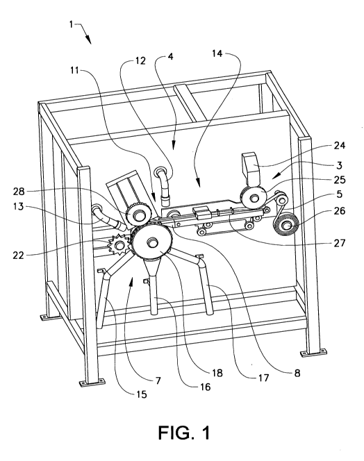
The device 1 illustrated in Fig. 1 is intended for producing portion packets 2
of a
smokeless tobacco product or non-tobacco snuff product, including producing
individual portion packets 2 of a smokeless tobacco product or non-tobacco
snuff
product, enclosing the individual portion packets 2 in a packaging material 5,
sealing
the package material 5 and identifying and rejecting defect packaged portion
packets 2.
Figure 1 shows the device 1 comprising a forming arrangement 3 in the form of
a
funnel-shaped feeder container 24 to which prepared smokeless tobacco product
or
non-tobacco snuff product is supplied in any conventional manner, such as
through
vertically disposed tubes the upper ends of which communicate with a snuff
preparatory reactor, not shown, and the lower ends of which are in
communication
with the feeder container 24. The forming arrangement 3 further comprises a
rotary
CA 02935637 2016-06-30
WO 2015/117760
PCT/EP2015/000237
17
portioning wheel 25 for portioning the product into portion packets 2.
Preparation of
product portion packets 2 is known from e.g. EP0921978.
The portioning wheel 25 expels the portion packets 2 in a row onto a packaging
material 5 in the form of a strip which may be made from a material that is
permeable to saliva and heat sealable, e.g. from viscose fibres bonded by a
thermoplastic bonding agent. The flat strip is being advanced in synchrony
with the
portions packets 2 from a reel 26 by means of an endless, perforated vacuum
suction belt 27 which is rotated, by means of a motor, not shown, around a low
pressure chamber.
The device 1 further comprises a packaging arrangement 4 at which the strip of
packaging material 5, being advanced along a feeding path by the suction belt
27, is
folded around the row of expelled portion packets 2. The strip of packaging
material
5 is further provided with a longitudinal seal 10 such that a tube of
packaging
material 5 enclosing portion packets 2 is formed.
The packaging arrangement 4 further comprises a unit for transversal sealing
11
that generates transversal seals 9 to the strip of packaging material in
between the
portion packets 2. In the example described here the transversal sealing unit
11
comprises a rotary welding wheel 28 interacting with a rotary supporting wheel
18.
The rotary welding wheel 28 is at its periphery provided with heated
transversally
arranged protruding formations 23 that presses onto/towards similar
transversally
arranged flanges 21 at the periphery of the supporting wheel 18 such as to
clamp
and transversally seal the strip of packaging material when placed between the
protruding formations 23 and flanges 21.
A cutting member 22, for transversally cutting the strip of packaging material
5, is
arranged downstream of the packaging arrangement 4. The cutting member 22 is
in
this case a cutting wheel provided with transversally arranged cutting blades
arranged to interact with the flanges 21 of the supporting wheel 18 and cut
the strip
of packaging material 5 in transversal direction along the transversal seal 9
such as
to separate the packaged portion packets 2.
CA 02935637 2016-06-30
WO 2015/117760 PCT/EP2015/000237
18
As best seen in Figure 2-5, the transversal seal 9 is formed by interaction of
the
protruding formations 23 provided to the rotary welding wheel 28 and the
transversally arranged flanges 21 at the periphery of the supporting wheel 18.
During operation, the rotary welding wheel 28 and the supporting wheel 18 turn
at
the feeding speed such that the protruding formations 23 and the flanges 21
coincide at a position along the strip of packaging material 5 corresponding
to that of
the intended transversal seal 9. A transversal seal 9 is thereby formed.
The supporting wheel 18 is also arranged to transport the packaging material 5
and
its enclosed portion packets 2 along a portion of its feeding path. A
perforated
vacuum band 19 is applied at the periphery of the supporting wheel 18. The
supporting wheel 18 supports the folded and sealed strip of packaging material
5
enclosing portion packets such that it, during operation, is being advanced
along its
feeding path while sucked into close contact with the peripheral surface of
the
supporting wheel 18 retaining the portion packets 2 by suction. Thus, the
portion
packets 2 follow the periphery of the turning supporting wheel 18 until the
individual
packaged portion packets 2 are released from the perforated vacuum band 19 by
a
rejection system 7 integrated in the supporting wheel 18.
The device 1 is further provided with a first sensor member in the form of a
first
vision sensor 12 arranged upstream of the unit for transversal sealing 11 and
downstream of the packaging arrangement 4, as illustrated in Figure 1. The
first
vision sensor 12 is placed above, and directed towards, the feeding path of
the
folded and sealed strip of packaging material 5 such that it captures images
and
generates data relating to the tube of packaging material 5 and the row of
portion
packets 2. A light emitting member 8, symbolically indicated with a bulb, is
located
below the feeding path, i.e. on an opposite side thereof, and directed towards
the
first vision sensor 12 to provide contrast, such that the images captured by
the first
vision sensor 12 clearly show how the product material is positioned in the
packaging material, in particular when using a thin, perforated white
packaging
material and a dark tobacco product. For example, the information generated
may
relate to the longitudinal alignment of each portion packet 2 in relation to
the strip of
packaging material 5. If two adjacent portion packets 2 have been placed too
close
to each other onto the material strip this will likely lead to an incorrect
transversal
CA 02935637 2016-06-30
WO 2015/117760
PCT/EP2015/000237
19
seal 9 in between the two and thus lead to defect portion packets 2. Such too
close
positioned portion packets 2 can be identified by the first vision sensor 12
and
thereby be sorted out and rejected by the rejection system 7 during operation
of the
device 1 before being placed in the can.
The sensor member forms part of, or is connected to, a control system, not
shown
comprising a computer, electronic connections, computer programs, actuators
etc.
Such a control system is known as such and is not described in detail here. In
short,
the sensor member sends image data to the control system that has access to
the
reference data and compares the image data with the reference data and
provides a
result. The control system also carries information relating to the operation
of the
downstream units, such as where the transversal seals 9 will be placed on the
strip
of packaging material 5 by the unit for transversal sealing 11. The control
system
also controls the operation of, e.g. the downstream rejection system. Hence;
if the
first vision sensor 12 detects the presence of product material at the
intended
position of the transversal seal, which is likely to lead to two defect
portion packets,
the control system can classify the two adjacent portion packets 2 as defect
already
at this stage and instruct the rejection system to reject these two portion
packets
when they arrive at the rejection system.
As illustrated in Figure 1, the device 1 also comprises a second vision sensor
13
arranged to capture image data of the transversally sealed portion packets 2
downstream of the unit for transversal sealing 11 and upstream of the cutting
member 22. The second vision sensor 13 is capable of detecting, for example,
appearance of the longitudinal seal 10 and/or the transversal seal 9 and if
there is
product material present outside of the packaging material. The captured image
data is compared by the control system against stored reference data as
described
above. Any defect packaged portion packets, also called pouches, are then
removed by means of the rejection system 7.
The control system is configured to control the rejection system 7 such that
if, using
the results of the comparison for classification, a portion pack 2 is deemed
faulty the
control system executes the rejection system 7 to eject the faulty portion
packet 2
into a first outlet 15 other than a product outlet 16, used for proper portion
packets,
=
CA 02935637 2016-06-30
WO 2015/117760 PCT/EP2015/000237
during operation. In this example proper portion packets 2, classified as non-
rejected, are, by means of control by the control system, ejected by the
rejection
system 7 into the product outlet 16 during operation of the device 1.
5 Figure 5 shows that the rejection system in this example forms an
integrated part of
the supporting wheel 18, the rejection system comprising channels 20 arranged
in
directions towards entrance ends of the first outlet 15, the product outlet 16
and a
further rejection outlet 17 respectively. The entrance ends, i.e. the inlets,
of the
outlets 15, 16, 17 mouth the perforated vacuum band 19 at different positions
in
10 relation to the feed direction so that portion packets 2 passes the
first outlet 15
before reaching the product outlet 16 and only after that they reach the
further
rejection outlet 17. The channels are arranged to lead pressurized air, fed
from an
air source, not shown, towards the perforated vacuum band 19. In this example,
one
channel 20 leads towards the first outlet, two channels 20 lead to the product
outlet
15 16 to allow for a higher flow of portion packets and one channel 20
leads towards
the further rejection outlet 17.
During operation of the device 1 the portion packets 2 reach the rejection
system
and become blown away and removed from the perforated vacuum band 19, by
20 supplying pressurized air into the respective channels 20, into their
respective outlet
15 or 16 depending on their classification, i.e. defect or correct. Thus,
selected
portion packets 2 can be rejected.
In an operative situation where no defect portion packets 2 are identified by
the first
and second vision sensor 12, 13, pressurized air is provided only to the two
channels leading air in the direction towards the product outlet 16, as
illustrated in
Fig. 5. In case of the identification of a defect portion packet 2, the
control system
instructs the rejection system 7 to supply air into the channel 20 directed
towards
the first outlet 15 at the time the defect portion packet 2 arrives in front
of the
corresponding channel 20 during its feeding path at the periphery of the wheel
18.
The second outlet 17 is a spare outlet that, for instance, can be used if the
product
outlet 16 becomes clogged.
CA 02935637 2016-06-30
WO 2015/117760
PCT/EP2015/000237
21
The invention is not limited by the embodiments described above but can be
modified in various ways within the scope of the claims. For instance, the
device
may comprise only one or more than two sensor members. The embodiment
described above comprises vision sensors. If the inventive device is provided
with
only one vision sensor it is preferably arranged downstream of the packaging
arrangement such as to allow quality control of e.g. both the longitudinal
seal and
the transversal seals at the same time.
The order of the outlets may be varied, e.g. the product outlet may be
arranged
upstream of the outlet for faulty portion packets. The number of channels
leading
pressurized air towards each outlet may be different than in the shown
embodiment.
Also the shape, length, etc. of the channels may be varied as also the general
position of the channels. They need not to be integrated in another structure,
and in
particular they need not to be integrated in a supporting wheel or suction
wheel.
As an alternative to the supporting wheel a straight/flat/planar
transportation
structure can be used. Transversal sealing and cutting can be carried out also
when
the material strip moves along such a structure. To remove selected packaged
portion packets from the feeding path of such a transportation structure, one
may
e.g. feed pressurized air from underneath the feeding path, similar to the
embodiment described above, or from a side of the feeding path.
Generally, the rejection system may be structured in different ways. A main
function
is to allow separation of proper products from defect products.