Note: Descriptions are shown in the official language in which they were submitted.
CA 02935730 2016-06-30
WO 2015/112721
PCT/US2015/012467
- 1 -
DISPLAY SYSTEMS AND METHODS
FIELD
[0001] The described embodiments relate generally to display systems and
methods for
displaying a product. More particularly, the embodiments relate to a display
stem and
product retainer for displaying a consumer product within in a retail store.
BACKGROUND
[0002] A retailer or other person may desire to make a product available
for use (e.g.,
testing) by a potential purchaser or other person. In some cases, the retailer
may further
desire to limit the potential purchaser's ability to remove the product from a
display area.
SUMMARY
[0003] A retailer may have a display model product that is representative
of products that
are available for purchase by a purchaser. In order to entice such a purchase,
the retailer
may make the display model available for use by the potential purchaser. To
promote
such use, a retailer may further desire to present the product in a consistent
and
aesthetically-pleasing way, thereby further enticing the potential purchaser
to handle and
test the item, and to minimize the interference of elements of a display stand
with the
potential purchaser's viewing and use of the product. The retailer, however,
may desire to
limit the ability of the potential purchaser to remove the display model from
a display
area (e.g., to prevent theft or other unauthorized use).
[0004] To accomplish this, the retailer may use a display system or
elements thereof
according to embodiments described herein.
[0005] In some embodiments, a display system for displaying a product
includes a
retainer for retaining the product, the retainer including a retainer body,
wherein at least a
portion of the retainer body defines a hemispherical shape, and a bracket
attached to the
retainer body, the bracket including at least two bracket arms configured to
extend around
opposing sides of the product, and a display stem defining a recess at a
proximal end
thereof, the recess shaped to receive the hemispherical portion of the
retainer body.
CA 02935730 2016-06-30
WO 2015/112721
PCT/US2015/012467
- 2 -
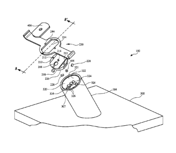
[0006] In some embodiments, a display system for displaying a product
includes a
retainer for retaining the product, the retainer including a retainer body
having a plurality
of first charging contacts on its outer surface, where at least a portion of
the retainer body
is hemispherical. The system may also include a display stem defining a recess
shaped to
receive the hemispherical retainer body, where the recess includes a plurality
of second
charging contacts. The first charging contacts and the second charging
contacts may be in
electrical communication when the retainer body is in the recess.
[0007] In some embodiments, a display system for displaying a product
includes a
retainer for retaining the product, the retainer including a retainer body
having at least one
first magnet coupled thereto, and a bracket attached to the retainer body, the
bracket
including at least two bracket arms configured to extend around opposing sides
of the
product, and a display stem defining a recess at a proximal end thereof, the
recess
defining an opening and least one second magnet disposed adjacent to the
opening,
wherein the at least one first magnet is configured to cause rotation of the
retainer body to
a predefined orientation when at least a portion of the retainer body is
disposed within the
recess of the display stem, if the retainer body is not in the predefined
orientation, and
wherein the at least one first magnet is configured to cause the rotation by
magnetic
attraction to the at least one second magnet.
[0008] In some embodiments, a display system for displaying a product
includes a
retainer for retaining the product, the retainer including a retainer body
having a plurality
of first magnets. The system may also include a display stem defining a recess
and an
opening, and the display stem may include a plurality second magnets disposed
adjacent
to the opening, the plurality of second magnets having alternating positive
and negative
polar orientations. The plurality of first magnets may be configured to cause
rotation of
the retainer body to at least one predefined orientation when at least a
portion of the
retainer body is disposed within the recess of the display stem, if the
retainer body is not
in the predefined orientation, and the plurality of first magnets may cause
the rotation by
magnetic attraction to a plurality of the second magnets having the opposite
polarity as
the plurality of first magnets.
[0009] In some embodiments, a display system for displaying a product
includes a
retainer body, at least one first magnet coupled to the retainer body, the at
least one first
magnet configured to cause rotation of the retainer body to a predefined
orientation when
CA 02935730 2016-06-30
WO 2015/112721
PCT/US2015/012467
- 3 -
at least a portion of the retainer body is disposed within a display stem, if
the retainer
body is not in the predefined orientation.
[0010] In some embodiments, a display system for displaying a product
includes a
retainer body; and a bracket attached to the retainer body, the bracket
including at least
two bracket pieces, each bracket piece having a bracket arm for extending
around
opposing sides of the product. The system may also include an auxiliary cable
having an
auxiliary plug, where the retainer body defines a plug recess to receive at
least a portion
of the auxiliary plug, and where a portion of each bracket piece wraps around
at least a
portion of the plug recess and the auxiliary cable to retain the auxiliary
plug within the
plug recess.
[0011] In some embodiments, a retainer for retaining a product includes a
retainer body
having a peak area, a base area, and a substantially smooth curved outer
surface, and a
bracket attached to the retainer body, the bracket including at least two
bracket arms
configured to retain the product with respect to the retainer, wherein at
least a portion of
the substantially smooth curved outer surface has a continuously changing
slope
extending from the peak area to the base area.
[0012] In some embodiments, a method of displaying a product includes
retaining the
product with respect to a retainer, wherein the retainer comprises a body
defining a
substantially smooth outer surface, retracting the retainer onto a distal end
of a display
stem using a tensioned cable coupled to the retainer and extending through the
display
stem, and orienting the retainer to a predefined orientation with respect to
the display
stem using magnetic forces if the retainer is not in the predefined
orientation.
[0013] In some embodiments, a method of detaching a cable to a product
retainer
includes positioning a cable connected to a product retainer within a notch of
a disconnect
tool, inserting at least two pins of a disconnect tool into at least two
disconnect apertures
located on the product retainer on opposing sides of a cable attached to the
product
retainer, and actuating a release mechanism disposed within the product
retainer in
response to the insertion of the at least two pins, where the at least two
pins are disposed
on opposing sides of the notch.
- 4 -
[0013a] In some further embodiments, the present invention provides a
display system for
displaying a product, the system comprising: a retainer for retaining the
product, the
retainer comprising: a retainer body having at least one first magnet coupled
thereto; and
a bracket attached to the retainer body, the bracket comprising at least two
bracket arms
configured to extend around opposing sides of the product; and a display stem
defining a
recess at a proximal end thereof, the recess defining an opening located at
the bottom of
the recess, and the display stem comprising at least one second magnet
disposed adjacent
to the opening, wherein the at least one first magnet is configured to cause
rotation of the
retainer body to a predefined orientation when at least a portion of the
retainer body is
disposed within the recess of the display stem, if the retainer body is not in
the predefined
orientation, and wherein the at least one first magnet is configured to cause
the rotation
by magnetic attraction to the at least one second magnet.
[0013b] Further aspects of the invention will become apparent upon reading
the following
detailed description and drawings, which illustrate the invention and
preferred
embodiments of the invention.
BRIEF DESCRIPTION OF THE DRAWINGS
[0014] The disclosure will be readily understood by the following detailed
description in
conjunction with the accompanying drawings, where like reference numerals
designate
like structural elements, and in which:
[0015] FIG. 1 shows a display system holding a product according to an
embodiment.
[0016] FIG. 2 shows a cross-sectional view of a display system according to
an
embodiment.
[0017] FIG. 3 shows a perspective view of a display system according to an
embodiment.
[0018] FIG. 4 shows a first perspective view of a retainer according to an
embodiment.
[0019] FIG. 5 shows a second perspective view of a retainer according to an
embodiment.
[0020] FIG. 6 shows a perspective view of a bracket according to an
embodiment.
[0021] FIG. 7 shows an exploded view of a display system according to an
embodiment.
[0022] FIG. 8 shows a cross-sectional view of the display system shown in
FIG. 7 along
line 8-8'.
[0023] FIG. 9 shows an assembled display system according to an embodiment.
CA 2935730 2017-08-09
=
-5-
100241 FIG. 10 shows a cross-sectional view of the display system shown in
FIG. 9 along
the line 10-10'.
[0025] FIG. 11 shows a bottom perspective view of a retainer according to
an
embodiment.
[0026] FIG. 12 shows a top perspective view of a retainer according to an
embodiment.
[0027] FIG. 13 shows a side view of a retainer according to an embodiment.
[0028] FIG. 14 shows a bottom view of a retainer according to an
embodiment.
[0029] FIG. 15 shows a cross-sectional view of a display stem according to
an
embodiment.
[0030] FIG. 16 shows a view of the display stem taken from the perspective
of arrow 16
of FIG. 15.
[0031] FIG. 17 shows an exploded view of a retainer according to an
embodiment.
[0032] FIGS. 18 and 19 show top views of portions of a retainer in
different assembly
states, according to an embodiment.
[0033] FIG. 20 shows an exploded view of part of a display stem according
to an
embodiment.
[0034] FIG. 21 shows a view of the display stem taken from the perspective
of arrow 16
of FIG. 15.
[0035] FIG. 22 shows an exploded view of part of a retainer according to an
embodiment.
[0036] FIG. 23 shows a bottom view of a retainer according to an
embodiment.
[0037] FIG. 24 shows a disconnect tool according to an embodiment.
[0038] FIG. 25 shows the operation of a disconnect tool according to an
embodiment.
[0039] FIG. 26 shows display systems holding multiple products according to
an
embodiment.
DETAILED DESCRIPTION
[0040] Reference will now be made in detail to representative embodiments
illustrated in
the accompanying drawings, in which like reference numerals are used to
indicate
identical or functionally similar elements. It should be understood that the
following
descriptions are not intended to limit the embodiments to one preferred
embodiment. To
the contrary, it is intended to cover alternatives, modifications, and
equivalents as can be
CA 2935730 2017-08-09
- 5a -
included within the scope of the described embodiments as defined by the
appended
claims.
[0041] References to "one embodiment", "an embodiment", "some embodiments",
"an
example embodiment", etc., indicate that the embodiment described may include
a
particular feature, structure, or characteristic, but every embodiment may not
necessarily
include the particular feature, structure, or characteristic. Moreover, such
phrases are not
necessarily referring to the same embodiment. Further, when a particular
feature,
structure, or characteristic is described in connection with an embodiment, it
is submitted
that it is within the knowledge of one skilled in the art to effect such
feature, structure, or
characteristic in connection with other embodiments whether or not explicitly
described.
[0042] A retailer may have a display model product that is representative
of products that
are available for purchase by a purchaser. In order to entice such a purchase,
the retailer
may make the display model available for use by the potential purchaser. The
retailer,
however, may desire to limit the ability of the potential purchaser to remove
the display
model from a display area (e.g., to prevent theft or other unauthorized use).
To
accomplish this, the retailer may use a stand as described herein, which may
include
security features. Although this document describes its display stand in terms
of a retailer
CA 2935730 2017-08-09
CA 02935730 2016-06-30
WO 2015/112721
PCT/US2015/012467
- 6 -
providing a display model for use by a potential purchaser, the display stand
can be
applied to any other suitable situation (e.g., any situation where use of an
item is desired
to be limited) such as, for example, a kiosk where a user may use displayed
item, or a
customer service station.
[0043] A retailer that makes a product available for use by a potential
purchaser may
further desire to present the product in an aesthetically-pleasing way,
thereby further
enticing the potential purchaser to handle and test the item, and to minimize
the
interference of elements of a display stand with the potential purchaser's
viewing and use
of the product. To further entice the potential purchaser, it may be desired
that the display
stand be configured to provide a consistent and aesthetically-pleasing
appearance, so as to
not detract from a potential purchaser's experience when viewing, handling,
and testing
the item.
[0044] As described, embodiments of the present invention relate to a
system and method
for displaying a product. The system may include a display stem and a retainer
that
cooperate to present a product to a user. The retainer may be attached to a
back side of a
product (e.g., an electronic device such as, for example, a phone, a tablet
computer, a
camera, a music player, a personal computer, a laptop computer, or a computer
peripheral) and may include a bracket that wraps around the back and sides of
the
product. The retainer may be hidden from view when the product is retained on
the
display stand. Such a low-profile design may increase aesthetic appeal of the
product by
minimizing potentially distracting visual impact attributable to the retainer.
This may
focus a potential customer's attention on the product rather than the retainer
or display
stem configuration. The display stem may include a recess for receiving at
least a portion
of the retainer, thereby hiding at least a portion of it from view. The
retainer may be
oriented within the recess in one or more predetermined positions so as to be
indexed to
such positions. For example, the retainer may be oriented to indexed positions
by
magnetic forces (e.g., magnets corresponding to the indexed positions).
[0045] In some embodiments, the retainer may be movably coupled to the
stem. For
example, it may have a seated position where the retainer rests relative to
the stem and a
released position where the retainer is movable and free from the stem. In
some
embodiments, the retainer may be coupled to a retaining cable that provides a
length of
cable that can be drawn out of the stem to allow a potential purchaser to
remove the
CA 02935730 2016-06-30
WO 2015/112721
PCT/US2015/012467
- 7 -
retainer, with a product secured thereon, from the stem. The retaining cable
may allow a
user to pick up and handle a product secured to the retainer, while preventing
theft of the
product. The retainer may include a bracket that secures a product to the
retainer. The
bracket may be configured as a single part or multiple parts. In some
embodiments, the
bracket includes two parts that couple together around a product thereby
securing the
product to the retainer.
[0046] A retailer may also desire that the display model be returned to its
original
location and orientation on its display stand after a potential purchaser has
finished
handling the display model, so that it is presented to the next potential
purchaser in the
location and orientation desired by the retailer. This can present an ordered,
aesthetically-
pleasing retail environment. Embodiments of the present invention can
automatically
return the display model to its original position and orientation on the
display stand. For
example, a retaining cable attached to a retainer coupled to the display model
may retract
to pull the device onto its display stem when the display model is released by
a person
handling it. And, in some embodiments, the retainer may have a shape so that
it
automatically seats into a recess of the display stem under the tension of the
retaining
cable, and does not get caught on a rim of the recess (e.g., a hemispherical
shape).
Further, in some embodiments, one or more alignment mechanisms such as, but
not
limited to, magnetic elements, may be used to automatically return the display
model to
its original location and orientation (or into one or more indexed
orientations). For
example, magnet elements of the retainer may rotate the retainer within the
recess by their
magnetic attraction to magnet elements of the display stem, thereby
automatically rotating
the display model with respect to the stem until it is in one of the indexed
locations (e.g.,
predetermined desired orientations). For example, the retainer may have
alignment
mechanisms that cause it to index to any desired orientation and/or number of
orientations. In some embodiments, it may index to four orientations: 00, 90 ,
180 , and
270 . Such orientations may correspond to portrait and landscape orientations
for a
display screen of the displayed item, which may orient displayed content to
correspond to
each orientation of the retainer as it is rotated between indexed positions.
[0047] The retainer may provide power to a product secured thereon. In some
embodiments, the retainer may include charging contacts configured to
electrically
communicate with corresponding charging contacts located on a display stem in
order to
CA 02935730 2016-06-30
WO 2015/112721
PCT/US2015/012467
- 8 -
provide power to a product. In some embodiments, the corresponding charging
contacts
may only be in electrical communication when the retainer is properly seated
on the
display stem (e.g., fully seated within a recess of the display stem in a
predetermined
orientation). In some embodiments, alignment mechanisms such as, but not
limited to,
magnetic elements may be used to facilitate the proper seating of the retainer
on the
display stem and thus facilitate electrical communication between the
corresponding
charging contacts.
[0048] These and other embodiments are discussed below with reference to
FIGS. 1-25.
However, those skilled in the art will readily appreciate that the detailed
description given
herein with respect to these Figures is for explanatory purposes only and
should not be
construed as limiting.
[0049] As shown in FIG. 1, embodiments of the present invention include a
display
system 10 for displaying a product 20 having a retainer 30 and a support
system 50.
Product 20 can be an item displayed for sale (e.g., as a display model).
Support system 50
can support retainer 30 having product 20 fixed thereto. In some embodiments,
support
system 50 is a table, shelf, wall, or other retail display structure. Support
system 50 may
be the same as or similar to support system 300 described herein. Display
system 10 can
be used to display and hold product 20 and may allow product 20, fixed to
retainer 30, to
be removed from support system 50 (e.g., for handling by a potential
purchaser) while
still retaining product 20. Support system 50 may include a display stem 40
for displaying
and holding retainer 30 having product 20 fixed thereto. In some embodiments,
display
stem 40 may be the same as or similar to display stem 304 described herein. In
some
embodiments, retainer 30 may be the same as or similar to retainer 200
described herein.
In some cases product 20 may be interactive, and may include a display screen.
Potential
purchasers may be able to pick product 20 up off of display stem 40 and return
it thereto,
or rotate product 20 on display stem 40 and interact with it while it remains
supported on
display stem 40.
[0050] To display and hold product 20 in an easily-accessible, rotatable,
and returnable
manner, retainer 30 and display stem 40 may be separable, and may removably
mate with
each other (e.g., by a node of retainer 30 (e.g., a protrusion therefrom,
forming a body of
the retainer) that interfaces with a recess of display stem 40 (or vice
versa). For example,
the node may be received within the recess while product 20 is supported by
display stem
CA 02935730 2016-06-30
WO 2015/112721
PCT/US2015/012467
-9-
40. The node may be configured to move within the recess. Retainer 30 and
display stem
40 may have various shapes configured to interface with each other. In some
embodiments, at least a portion of the node is sized and dimensioned (shaped)
to
correspond with at least a portion of the recess. The node and recess may be
the
positive/negative of one another. In some embodiments, the recess and node may
have
corresponding rounded shapes including, but not limited to, cylindrical
shapes, sloping
cylindrical shapes, egg shapes, and hemispherical shapes. Such rounded shapes
may help
facilitate rotation of product 20 on display stem 40, and removal or
replacement of
product 20 on display stem 40.
[0051] To help keep product 20 at a desired orientation for display, or at
one of a number
of desired orientations, in some embodiments display system 10 includes an
alignment
mechanism, which may be an indexing mechanism to align product 20 to one of
multiple
indexed positions. Such indexing mechanism may cause displayed product 20 to
automatically rotate relative to display stem 40 to one of the indexed
orientations. In
some embodiments the indexing mechanism of display system 10 is indexed to
cause
product 20 to rotate to one of 00, 900, 180 , 270 , to match the normal
viewing
orientations of a display screen of product 20. For example, some display
screens can
auto-rotate in 90 degree increments depending on their orientation, so that
displayed
media is oriented right-side-up. Media displayed on such a product 20 retained
by display
system 10 will then be oriented right-side-up in portrait or landscape mode,
since display
system 10 can auto-rotate product 20 into one of portrait or landscape
orientation.
[0052] FIG. 2 shows a display system 100 for displaying a product 102
according to
some embodiments. Display system 100 may generally correspond to display
system 10
described above. Display system 100 may include a retainer 200 and a support
system
300. As shown in FIG. 2, support system 300 can support retainer 200 having
product 102
fixed thereto. Display system 100 can be used to display and hold product 102
and may
allow product 102, fixed to retainer 200, to be removed from support system
300 (e.g., for
handling by a potential purchaser) while still retaining product 102. As shown
in FIG. 2,
this may be accomplished using a retaining cable 328 attached to retainer 200.
Retaining
cable 328 can be retracted within (and/or through) support system 300 when
product 102,
fixed to retainer 200, is replaced on support system 300, as described further
below.
CA 02935730 2016-06-30
WO 2015/112721
PCT/US2015/012467
- 10 -
[0053] As shown in FIG. 2, retainer 200 includes a retainer body 202 and a
bracket 230
for holding product 102. Retainer body 202 has an outer surface 218 with a
lower area
204 and an upper area 220 (e.g., a base area 204 and a peak area 220). Base
area 204 of
retainer body 202 includes a fixing surface 206 that is engaged with a bottom
surface 236
of bracket 230. Peak area 220 is an area or point of outer surface 218 that is
farthest from
base area 204. In some embodiments, peak area 220 is farthest from base area
204 in a
direction orthogonal to at least a portion of fixing surface 206. In some
embodiments, at
least one first magnetic element, such as at least one first magnet 228, is
coupled to
retainer body 202. In some embodiments, at least one first magnet 228 forms a
portion of
outer surface 218. In some embodiments, at least one first magnet 228 is
embedded
within retainer body 202 (e.g., within a cavity thereof). Retaining cable 328
may attach to
retainer body 202 (e.g., via a coupling element 222, see FIG. 5). And
retaining cable 328
may be secured to retainer body 202 using any suitable technique including,
but not
limited to, one or more of adhesives (e.g., glue or epoxy), screw-type
fittings, friction-
type fittings, luer lock fittings, or welding. In some embodiments retaining
cable 328
attaches to retainer body 202 at or adjacent to peak area 220, along a central
axis of
retainer body 202. In some embodiments, a plurality (e.g., 2, 3, or 4) of
first magnets 228
are disposed around retaining cable 328 (e.g., about a center axis of retainer
body 202). In
some embodiments, the plurality of first magnets 228 are equidistant from each
other
about retaining cable 328.
[0054] Additionally, retainer body 202 may include a security switch 214 on
fixing
surface 206. Security switch 214 may be used to detect whether or not product
102 is
attached to retainer 200, and can trigger an alarm in response to product 102
being
removed from retainer 200. For example, in some embodiments, when product 102
is
coupled to retainer body 202, product 102 may engage (or disengage) security
switch 214
(e.g., by backside 104 of product 102 depressing a button of security switch
214).
Security switch 214 may be communicatively coupled to an alarm or other alert
such that
the alert can be triggered by removal of product 102 from retainer body 202.
Such
removal of product 102 from retainer body 202 may disengage (or engage)
security
switch 214, thereby triggering the alert. In some embodiments, retainer body
202 may
include indicators 256 for altering a user that product 102 has been removed
from retainer
body 202 (see, e.g., FIGS. 11 and 13). Indicators 256 may include, but are not
limited to,
CA 02935730 2016-06-30
WO 2015/112721
PCT/US2015/012467
- 11 -
lights (e.g., light-emitting diode (LEDs)) and/or audio indicators such as
buzzers or
ringers. In some embodiments, display stem 304 may alternatively or
additionally include
indicators 256. In some embodiments, the alert may also be triggered in the
event that
retaining cable 328 is severed.
[0055] Bracket 230 includes bottom surface 236 and a top surface 232. In
some
embodiments bracket 230 may include one or more bracket arms 238. When product
102
is fixed to retainer 200, a backside 104 of product 102 in some embodiments
may rest on
fixing surface 206 and top surface 232, and bracket arms 238 aid in securing
product 102
to retainer 200. Each bracket arm 238 includes a vertical support 240 and a
horizontal
support 242.
[0056] As shown in FIG. 2, support system 300 includes a support 302 and a
display stem
304. Support 302 can be, for example, a structural feature of a building or an
article of
furniture. For example, support 302 can be a tabletop, a countertop, a shelf,
a floor, a
ceiling, or a wall. A distal end 306 of display stem 304 is fixed to support
302. In some
embodiments, distal end 306 is fixed to support 302 in such a way that removal
without
damaging support system 300 can be achieved only with specialized tools and/or
access
not available to potential purchasers, and/or can be achieved only by
operations likely to
attract attention (e.g., fasteners accessible only from underneath a display
table or only
un-fastenable with a non-standard tool).
[0057] Display stem 304 can extend from support at any angle 335, for
example, 90 as
shown in FIG. 2, or at an oblique angle 335 as shown in FIG. 1. Such oblique
angle 335
may be, for example, 45 , 20 , or 7 . Display stem 304 may be connected to
support 302
via distal end 306 and a connector 308 (see, for example, FIG. 10). Display
stem 304 may
be a hollow structure defined by a stem wall 310 and a passage 314. In some
embodiments, display stem 304 may be cylindrical or frustoconical. A recess
320, located
at a proximal end 312 of display stem 304, forms the upper most part of
passage 314.
Distal to recess 320, passage 314 may narrow (e.g., at throat area 315).
Throat area 315
may be directly distal to recess 320, and in some embodiments, is located in
an upper half
of display stem 304. In some embodiments, recess 320 may be formed by an
insert 318
attached to proximal end 312 of display stem 304 (see, e.g., FIG. 15).
[0058] Recess 320 may define a top opening 321 configured to receive
retainer body 202
and bottom opening 323 that connects recess 320 to the rest of passage 314.
Recess 320
CA 02935730 2016-06-30
WO 2015/112721
PCT/US2015/012467
- 12 -
includes an inner wall 322 that is shaped to receive at least a portion of
retainer body 202,
to thereby hide retainer body from view when it is received within recess 320.
In some
embodiments, recess 320 is shaped to receive the entire retainer body 202. In
some
embodiments, at least one second magnetic element, such as at least one second
magnet
326, may be disposed adjacent to recess 320 in display stem 304. In some
embodiments, a
surface of at least one second magnet 326 forms a portion of inner wall 322.
In some
embodiments, a plurality (e.g., 2, 3, or 4) of second magnets 326 are disposed
around
passage 314. In some embodiments, the plurality of second magnets 326 are
equidistant
from each other about passage 314. Second magnets 326 may be positioned to
interact
with first magnets 228 when retainer body 202 is received within recess 320.
To facilitate
such interaction recess 320 and retainer body 202 may have mating shapes, so
that their
surfaces (and magnets) are in close proximity when they are engaged together.
For
example, as shown in FIGS. 1, 8, and 10, retainer body 202 may have a positive
shape
and recess 320 may have a negative shape that mates together with the positive
shape. In
some embodiments, the positive and negative shapes are positive and negative
hemispherical shapes. First magnets 228 of retainer body 202 may cause
retainer body
202 to rotate so that first magnets 228 are as close as possible to second
magnets 326 of
display stem 304, due to magnetic attraction between the magnets. This
interaction
between first magnets 228 and second magnets 326 serves to automatically
orient retainer
200 (and retained product 102) when it is received within recess 320 of
display stem 304.
[0059] While FIGS. 1-25 show display stem 304 having a recess 320 and
retainer body
202 having a generally continuous convex curvature, recess 320 and retainer
body 202
may have various shapes configured to interface with each other. For example,
retainer
body 202 may include a node that interfaces with recess 320. The node may be
configured to move within recess 320. In some embodiments, at least a portion
of the
node is sized and dimensioned (shaped) to correspond with at least a portion
of recess
320. The node and recess 320 may be the positive/negative of one another. In
some
embodiments, recess 320 may include a protrusion sized and dimensioned
(shaped) to
correspond with a recess located on retainer 200 (e.g., a recess formed in
retainer body
202). In some embodiments recess 320 may be replaced with a protrusion sized
and
dimensioned (shaped) to correspond with a recess formed in retainer body 202.
Recess
320 and retainer body 202 may include any suitable corresponding sizes and
shapes. In
CA 02935730 2016-06-30
WO 2015/112721
PCT/US2015/012467
- 13 -
some embodiments, recess 320 and retainer body 202 may have corresponding
tapered
shapes. In some embodiments, recess 320 and retainer body 202 may have
corresponding
rounded shapes including, but not limited to, cylindrical shapes, sloping
cylindrical
shapes, egg shapes, and hemispherical shapes.
[0060] In some embodiments retaining cable 328 extends through passage 314
of display
stem 304. Passing retaining cable 328 through passage 314 helps hide it from
view and
makes it less susceptible to tangling or damage. One end 329 of retaining
cable 328 is
connected to retainer body 202 and the other end is connected to an anchor
330. Retaining
cable 328 may also be connected to a power/data source 332. Power/data source
332 is
configured to supply power and/or data to product 102 when product 102 is
fixed to
retainer 200. For example, power and/or data may be transmitted through
retainer body
202 to an auxiliary cable 402 (see FIG. 4) that connects to a power and/or
data port on
product 102.
[0061] Anchor 330 may include or be a retraction mechanism 334 (see FIG.
2).
Retraction mechanism 334 may be configured to apply tension to retaining cable
328 to
pull retainer 200 towards retraction mechanism 334 when the applied tension is
not
overcome by another force on retainer 200 (e.g., by a person handling retained
product
102). In some embodiments, refraction mechanism 334 may include, for example,
a
spring-loaded pulley, a counterweight, or any other suitable means for
retracting a cable.
Refraction mechanism 334, via retaining cable 328, holds retainer 200 against
proximal
end 312 of display stem 304 when retainer body 202 is received in recess 320
(see, e.g.,
FIGS. 9 and 10). When a user picks up product 102, this action applies enough
force to
overcome the tension applied by retraction mechanism 334, allowing retaining
cable 328
to be drawn out through passage 314. In some embodiments, the length of cable
328 that
can be drawn out is limited, thereby limiting the distance that retainer 200
and retained
product 102 can be taken from support system 300. This can prevent retaining
cable 328
from being completely removed from support system 300. In some embodiments,
the
length of cable 328 that can be drawn out is limited to a predefined length.
In this way
display system can be used to provide varying levels of security.
[0062] For example, in some embodiments, the predetermined length of
retaining cable
328 that can be drawn out may be zero such that retaining cable 328 holds
retainer 200
against proximal end 312 (e.g., such that retainer body 202 of retainer 200
cannot be
CA 02935730 2016-06-30
WO 2015/112721
PCT/US2015/012467
- 14 -
removed from recess 320 of display stem 304). In effect, the retaining cable
328 cannot
be drawn out in this configuration. Such a configuration prevents a customer
from picking
up product 102, but increases the difficulty of stealing product 102. If
product 102 cannot
be removed from display stem 304, a potential thief cannot rely on a played-
out length of
retaining cable 328 to provide leverage to separate product 102 from retainer
200 and/or
support system 300 (e.g., by wrapping the cable around his arm and applying a
sudden
force).
[0063] In another embodiment, the predetermined length of retaining cable
328 that can
be drawn out may be an intermediate length, such as, for example, a length
that allows a
user to pull out at most 6 inches of retaining cable 328. Such a length allows
a customer
to pick up product 102 and inspect it. This allows potential purchasers to
more thoroughly
inspect product 102, while still restricting the amount of leverage a
potential thief has for
separating product 102 from retainer 200 and/or support system 300.
[0064] In another embodiment, the predetermined length of retaining cable
328 that can
be drawn out may be a long length, such as, for example, 1 meter. Such a
length provides
a potential customer with the most freedom in testing the product, but can
provide a
potential thief with a greater amount of leverage compared to the short and
intermediate
lengths.
[0065] The short, intermediate, and long predetermined lengths for
retaining cable 328
can be selected for use by a retailer depending on the situation in which
display system
100 is to be used. For example, the retailer may select different lengths
depending on the
perceived security risk (e.g., long for low-risk, intermediate for medium-
risk, and short
for high-risk), the product 102 being displayed (e.g., intermediate for a
tablet computer
since tablet computers are often operated at arm's length, or long for a
smartphone, since
smartphones are often operated closer to a user's head), or some combination
of these
and/or other considerations. Any of these or other cases can be accommodated
simply by
changing the predefined length of retaining cable 328 that can be drawn out.
Thus,
display system 100 can provide a single display solution across a wide range
of a retailer's
different products and security risks.
[0066] A perspective view of a display stem 304 according to an embodiment
is shown in
FIG. 3. Recess 320, located at proximal end 312, includes an inner wall 322
having a
hemispherical shape with an opening leading to throat area 315. While inner
wall 322 is
CA 02935730 2016-06-30
WO 2015/112721
PCT/US2015/012467
- 15 -
shown having a hemispherical shape in FIG. 3, recess 320 may have a different
shape in
other embodiments, including but not limited to an elliptical shape, a conical
shape, an
egg shape, or a cylindrical shape. In some embodiments the shape of recess 320
corresponds with the shape of outer surface 218 of retainer body 202. In some
embodiments, a majority of the shape of recess 320 conforms exactly to the
shape of
outer surface 218. The correspondence in hemispherical shape between recess
320 and
retainer body 202 of some embodiments helps retainer 200 freely rotate on
display stem
304. This free rotation can help alignment mechanism (e.g., magnets as
described) rotate
retainer 200 to an indexed location with minimal interference from mating
surfaces of
retainer body 202 and recess 320. Since it is a generally smooth curve, the
hemispherical
shape of retainer body 202 also helps minimize the potential for retainer body
to catch on
edges of display stem 304 as it is drawn toward (e.g., by retraction mechanism
334) and
enters recess 320
[0067] As shown in FIG. 3, inner wall 322 includes a plurality of second
magnets 326.
Second magnets 326 are disposed in cavities 324 of display stem 304 (see FIGS.
7 and 8)
and define a portion of inner wall 322. Second magnets 326 may alternatively
be disposed
below inner wall 322.
[0068] FIG. 3 also shows passage 314 having a circular cross section. In
other
embodiments passage 314 may have a different cross-sectional shape, including
but not
limited to elliptical or polygonal. In some embodiments, display stem wall 310
is a single
monolithic piece (see, e.g., FIGS. 2, 8, and 10). In some embodiments, display
stem wall
310 is made of aluminum. In some embodiments, the surface of display stem wall
310 is
finished using blasting (e.g., sand blasting) and anodization.
[0069] A retainer body 202 according to an embodiment is shown in FIGS. 4
and 5. FIG.
4 shows base area 204 including fixing surface 206 according to one
embodiment. Fixing
surface 206 has a depressed area 210 and a protruded area 211 for together
receiving a
portion of bracket 230 and non-rotationally securing bracket 230 to retainer
body 202 (see
FIG. 9). Fixing surface 206 may define one or more holes 212 configured to
accept a
fastening mechanism (e.g., screws, bolts, pins, rivets, detents) that secure
retainer body
202 to bracket 230. Holes 212 may be threaded or non-threaded. Alternatively
or
additionally, retainer body 202 may be fastened to bracket 230 using other
fastening
mechanisms such as, for example, adhesives or welding.
CA 02935730 2016-06-30
WO 2015/112721
PCT/US2015/012467
- 16 -
[0070] In some embodiments, fixing surface 206 includes a cable access 208,
which may
provide access for an auxiliary cable 402, which may be a data/power cable or
other
linkage, and which may connect to a port on product 102 to provide data and/or
power to
product 102. In some embodiments, data and/or power can be provided to cable
access
208 through retaining cable 328, which may receive such data and/or power from
power/data source 332 (see FIG. 2). Cable access 208 may be a cable pass-
through
through which the power/data cable can pass, or may be an outlet configured to
receive a
data/power cable plug from, e.g., auxiliary cable 402. The interior of
retainer body 202
may include circuitry and/or electronics for delivering power and/or data to
auxiliary
cable 402. In this way, product 102 can receive power and/or data by being
connected to
auxiliary cable 402, which, in the case of an electronic device, may
facilitate its operation
and testing by a potential purchaser. In some embodiments, retainer body 202
is a single
monolithic piece. In some embodiments, retainer body 202 may include multiple
pieces
(e.g., as discussed below in reference to FIG. 12).
[0071] Any suitable outlet and plug combination can be used at either end
of auxiliary
cable 402 to provide such power and/or data transmission through cable access
208 to
product 102, such as, for example, Universal Serial Bus (USB), micro-USB, mini-
USB,
Advanced Technology Attachment (ATA) (e.g., Parallel ATA, Serial ATA), or any
other
standard or proprietary connection format. In some embodiments, cable access
208 can be
coupled to a cable (e.g., a data and/or power cable) running through or itself
forming
retaining cable 328.
[0072] In some embodiments, fixing surface 206 includes security switch
214. Security
switch 214 may be communicatively coupled to an alarm or other alert such that
the alert
can be triggered by removal of product 102 from retainer 200. Such removal of
product
102 from retainer 200 may disengage (or engage) security switch 214, thereby
triggering
the alert.
[0073] FIG. 5 shows a perspective view of an underside 216 of retainer body
202
according to an embodiment. Underside 216 is defined by a substantially smooth
curved
outer surface 218. In some embodiments, underside 216 includes at least one
slot 224 to
provide access to holes 212. In some embodiments, underside 216 defines an
opening
forming coupling element 222 to connect to a proximal portion of retaining
cable 328.
Coupling element 222 may be configured to receive and secure one end 329 of
retaining
CA 02935730 2016-06-30
WO 2015/112721
PCT/US2015/012467
- 17 -
cable 328 to retainer body 202 as discussed above in reference to FIG. 2. In
some
embodiments, underside 216 defines cavities 226 disposed around coupling
element 222
for receiving first magnets 228. In some embodiments, when first magnets 228
are
present in cavities 226 their outer surfaces align with a portion of outer
surface 218. In
some embodiments, first magnets 228 may alternatively be disposed below outer
surface
218 (e.g., embedded within retainer body 202).
[0074] In some embodiments, underside 216 of retainer body 202 has a
substantially
smooth shape defined by substantially smooth curved outer surface 218. In
other words,
in some embodiments outer surface 218 defines a continuous curvature where
interruptions are due only to recesses or openings to accommodate magnets or
fastening
elements, as described above (e.g., first magnets 228, slots 224, and coupling
element
222). In some embodiments, the continuous curvature of outer surface 218
curves in only
one direction (i.e., it does not have curves with different directions of
inflection). For
example, as shown in FIG. 5, underside 216 is a hemisphere (i.e., it has a
hemispherical
outer surface 218). In some embodiments, outer surface 218 includes a portion
extending
from peak area 220 to base area 204 that is completely smooth, containing no
interruptions from surface features (see, e.g., path 219 in FIG. 5). In some
embodiments,
at least a portion of outer surface 218 has a continuous and non-zero slope
extending from
peak area 220 to base area 204 (see, e.g., path 219 in FIG. 5). In some
embodiments,
outer surface 218 has a continuously increasing slope extending from peak area
220 to
base area 204 (see, e.g., path 219 in FIG. 5). In some embodiments, outer
surface 218 has
a slope with a constant curvature extending from peak area 220 to base area
204 (see, e.g.,
path 219 in FIG. 5). In some embodiments, underside 216 may have a shape other
than a
hemisphere, such as, for example, an elliptical or frustoconical shape.
[0075] As shown in FIG. 5, peak area 220 is the point or area on outer
surface 218 that is
farthest way from base area 204 in a direction orthogonal to at least a
portion of fixing
surface 206. For example, in FIG. 5 peak area 220 is the perimeter around
coupling
element 222. Base area 204 is immediately adjacent bracket 230.
[0076] The shape of outer surface 218 allows retainer body 202 to easily
slide out of
recess 320 when product 102 is picked up by a user and to easily slide into
recess 320
when a user places retainer 200 onto display stem 304 or retaining cable 328
is retracted
by retraction mechanism 334. The smooth curved outer surface 218 reduces
friction and
CA 02935730 2016-06-30
WO 2015/112721
PCT/US2015/012467
- 18 -
the potential for retainer body 202 to become caught on rim a 307 of display
stem 304
(thereby not seating properly within recess 320). This can also reduce the
potential for
damage to retainer 200 and display stem 304, when engaging or disengaging
retainer 200
and display stem 304. Additionally, it ensures that retainer body 202 always
fits into
recess 320 no matter its orientation.
[0077] In combination with retraction mechanism 334, which pulls retainer
200 and
retained product 102 toward display stem 304 when no outside force overcomes
the
tension that retraction mechanism 334 applies to retaining cable 328 (e.g.,
when retained
product 102 is released by a handler), the shape of outer surface 218 and
ensures that
product 102 automatically re-seats itself into recess 320 under tension of
retaining cable
328, in order to repeatably be displayed in a predefined position without
requiring
external interaction by a handler of product 102. The hemispherical shape of
outer surface
218 is well-suited to achieve these ends due at least in part to its lack of
protrusions or
corners around its side surfaces, so that its side surfaces slide over rim 307
without
interruption under power of the tension provided by retraction mechanism 334.
Hemispherical outer surface 218 can thereby be pulled completely within recess
320,
thereby re-seating itself and hiding itself from view.
[0078] Furthermore, in some embodiments being seated in recess 320 brings
first
magnets 228 and second magnets 326 in close enough proximity that they can
magnetically interact with each other to both retain retainer body 202 within
recess 320
and rotate retainer 200 and retained product 102 relative to display stem 304
so that
retained product 102 is oriented in a predefined position, as described
elsewhere herein.
The hemispherical shape of outer surface 218 is well-suited to achieve these
ends due at
least in part to its lack or protrusions or corners around its side surfaces,
which allow it to
rotate within recess 320.
[0079] A bracket 230 according to an embodiment is shown in FIG. 6. In some
embodiments, bracket 230 includes a center portion 233 and two bracket arms
238.
Bracket arms 238 extend to and around opposing sides of retained product 102,
to thereby
fix product to retainer 200 and to prevent its removal therefrom. While FIG. 6
shows two
bracket arms 238, in some embodiments bracket 230 may include any number of
bracket
arms, for example, four bracket arms.
CA 02935730 2016-06-30
WO 2015/112721
PCT/US2015/012467
- 19 -
[0080] Since bracket arms 238 only extend a short distance over the front
surface of
retained product 102 (e.g., just enough to securely retain product 102) and
are limited to
discrete positions centrally-located and occupying a small proportion of the
length of
product 102, they are able to retain product 102 without covering a display
screen or other
operative feature of product 102, to thereby present product 102 to a
potential purchaser
with minimal visual impact so that the potential purchaser can inspect product
102 with
minimal distraction from display system 100. In some embodiments, bracket arms
238
may alternatively or additionally include other fixing elements such as, for
example,
screws, snaps, rivets, buckles, detents, bolts, press fit, or adhesive (e.g.,
glue, epoxy,
adhesive tape) to couple product 102 to retainer 200.
[0081] In some embodiments, center portion 233 defines a central opening
234, which
may mate with fixing surface 206 on retainer body 202. For example, a
perimeter of
protruded area 211 may correspond to a perimeter of central opening 234 such
that
protruded area 211 occupies central opening 234 when bracket 230 is mated with
retainer
body 202.
[0082] In some embodiments, center portion 233 also defines holes 244
configured to
align with holes 212 of retainer body 202. In some embodiments, center portion
233 also
includes a cable aperture 246 configured to align with cable access 208 for
receiving and
allowing auxiliary cable 402 to pass from within to without central opening
234. In some
embodiments, bracket 230 is formed of a single piece (see, e.g., FIG. 6). For
example,
bracket 230 may be formed of a single extruded piece that is machined into its
final
shape.
[0083] In some embodiments, bracket 230 is formed of two pieces (e.g., a
first piece 290
and a second piece 294, as discussed below in regards to FIGS. 17-19). A two-
piece
bracket 230 may increase the modularity of retainer 200. For example, pieces
290 and
294 may be individually replaced in the event that one of them is damaged.
Additionally,
a two-piece bracket 230 may increase the ease of assembling retainer 200 and
attaching
product 102 to retainer 200 since the pieces can move relative to one another,
e.g., to
receive product 102 between portions of bracket 230.
[0084] In some embodiments, bracket 230 has a thickness of approximately
3mm, which
provides a minimal visual impact while still providing sufficient strength to
securely
retain product 102. In other embodiments, however, bracket 230 may have
greater or
CA 02935730 2016-06-30
WO 2015/112721
PCT/US2015/012467
- 20 -
lesser thickness. In some embodiments, bracket 230 is made out of aluminum,
for
example, 6063 aluminum alloy. In some embodiments, the surface of bracket 230
is
finished using blasting (e.g., sand blasting) and anodization.
[0085] In some embodiments, a fixing element 406 (see FIGS. 7 and 8) may be
provided
on retainer body 202, disposed on fixing surface 206 to contribute to
retention of product
102 on retainer 200. Fixing element 406 may be disposed on protruded area 211
in order
to come into contact with product 102. For example, fixing element 406 may be
an
adhesive, such as, for example, glue, epoxy, or adhesive tape (e.g., a double
coated
acrylic foam tape). In some embodiments, fixing element 406 may alternatively
or
additionally be a mechanical fastener such as, for example, a screw, snap,
rivet, buckle,
detent, bolt, or press fit.
[0086] The engagement between retainer body 202 and bracket 230 as well as
the
operation of display system 100 will be further described with reference to
FIGS. 7-10.
Fixing surface 206 having depressed areas 210 and protruded area 211 on
retainer body
202 mates with center portion 233 of bracket 230 such that part of fixing
surface 206
extends into center portion 233 (see FIG. 9). The mating configuration between
fixing
surface 206 and center portion 233 does not define a circular shape, to ensure
that retainer
body 202 and bracket 230 cannot rotate relative to each other, thereby
increasing the
strength of retainer 200 and ensuring repeatability in orientation relative to
display stem
304. Furthermore, the mating ensures that holes 212 and 244 on retainer body
202 and
bracket 230, respectively, are aligned, and prevents shear stress from being
placed on
fasteners 404 occupying holes 212 and 244.
[0087] Fasteners 404 (e.g., screws, bolts, pins, rivets, see FIG. 7) are
inserted within
aligned holes 212 and 244 to secure retainer body 202 to bracket 230. In some
embodiments holes 212 and 244 are oriented in a direction parallel to the axis
of rotation
502 of retainer 200 (which may coincide with the center axis of retainer body
202). Axis
of rotation 502 of retainer 200 is the axis extending through the center of
retainer body
202 at a direction orthogonal to fixing surface 206 (see FIG. 8). This
orientation provides
optimal strength for the connection between retainer body 202 and bracket 230
since
shear stress is not placed on fasteners 404 in the event a thief attempts to
pull product 102
off of retainer 200, and so the chances of failure of fasteners 404 are
reduced. In some
CA 02935730 2016-06-30
WO 2015/112721
PCT/US2015/012467
- 21 -
embodiments, fasteners 404 may be held within retainer body 202 such that they
cannot
fall out of retainer body 202 and cannot be removed by a user (e.g., a retail
store owner).
[0088] As discussed elsewhere herein, in some embodiments retaining cable
328 and
magnets 228 and 326 may be used to hold retainer 200 on proximal end 312 of
display
stem 304. When retainer 200 is placed onto or retracted by retraction
mechanism 334
onto proximal end 312, retainer body 202 fits into recess 320 and magnetic
forces
between first magnets 228 and second magnets 326 automatically orient retainer
body
202 within recess 320. The interaction between first magnets 228, second
magnets 326,
retraction mechanism 334 and retaining cable 328, outer surface 218, and
recess 320
ensures that product 102 is always returned to and displayed in its
predetermined position
and orientation, to help a retailer ensure its di splay in an aesthetically
appealing position.
[0089] To apply magnetic attractive forces both axially along axis 502 (to
help draw and
retain retainer body 202 within recess 320) and orthogonally to axis 502 (to
help rotate
retainer 200 with respect to display stem 304), magnets 228 and 326 may be
oriented to
direct their magnetic fields obliquely with respect to axis 502, such that
their attractive
forces apply at least a component force parallel to axis 502 and a component
orthogonal
to axis 502. Further, first magnets 228 may be positioned such that they are
disposed in an
oblique direction from second magnets 326 with respect to axis 502. In some
embodiments, this oblique direction is oriented such that a line through the
oblique
direction (e.g., line 504 in FIG. 8) would intersect axis 502.
[0090] Substantially smooth outer surface 218 ensures that retainer body
always slides
into, i.e., self-locates in, recess 320 under the tension applied by
refraction mechanism
334 through retaining cable 328, thereby ensuring that product 102 is always
displayed in
a desired position (e.g., facing potential purchasers) and is not displayed in
an off-kilter or
dangling position. In some embodiments the size and shape of retainer body 202
is such
that recess 320 receives the entire retainer body 202 (see FIG. 10). This
results in a low-
profile appearance that may be more aesthetically appealing to potential
customers. In
some embodiments, however, recess 320 only receives a portion of retainer body
202.
[0091] Once retainer body 202 slides into recess 320, first magnets 228 and
second
magnets 326 serve to automatically orient retainer 200 into desired positions.
For
example, display system 100 could employ four first magnets 228 and four
second
magnets 326, which automatically rotate retainer 200 to be oriented into one
of four
CA 02935730 2016-06-30
WO 2015/112721
PCT/US2015/012467
- 22 -
positions, each separated by 90 (e.g., promoting orientation at 0 , 90 , 180
, 270 ). Such
a configuration ensures that product 102 always returns to a vertical or
horizontal
orientation, which may be more aesthetically appealing to potential
purchasers. For
example, FIG. 26 shows product 102 oriented at 0 , 90 , 180 , and 270
(products 102A,
102B, 102C, 102D, respectively).
[0092] For embodiments having any or no length of cable 328 that can be
drawn out,
substantially smooth outer surface 218 and magnets 228 and 326 allow smooth
rotation of
product 102 between predefined desired rotational positions. In embodiments
having
intermediate or long length of cable 328 that can be drawn out, these features
ensure that
product 102 always returns to a predefined desired rotational position upon
return to
display stem 304. For example, when a user drops or releases product 102,
retraction
mechanism 334 retracts retaining cable 328 thereby pulling retainer body 202
into recess
320. Once in recess 320, magnets 228 and 326 automatically orient retainer
body 202 and
retained product 102 into a desired position.
[0093] While the above example describes four first magnets and four second
magnets,
any number of magnets may be used to automatically orient retainer body 202 in
recess
320 at any desired angle (i.e. rotational orientation), and the number of
first magnets 228
need not be the same as the number of second magnets 326. The orientation(s)
of retainer
body 202 may be based on the location and position of first magnets 228 and
second
magnets 326. In some embodiments, the orientations are radially separated by
at least 90
degrees of rotation. In some embodiments, the orientations are radially
separated by 90
degrees of rotation.
[0094] Magnets described herein (e.g., magnets 228 and 326) may include,
but are not
limited to, rare earth magnets, such as Neodymium magnets, or electromagnets.
Magnets
described herein (e.g., magnets 228 and 326) may be replaced with material
that is
attractive to magnets (e.g., ferromagnetic material or ferrimagnetic
material). For
example, where magnetic attraction is described above between two magnets,
either one
of the magnets in the pair may be replaced with a magnetically-attractive
material;
magnetic attraction will still exist therebetween. In some embodiments, first
and second
magnets may be cylindrical in shape, the cylinder having a diameter in the
range of 3 mm
to 3.5 mm and a length in the range of 2.5 mm to 3.5 mm. In some embodiments,
retainer
CA 02935730 2016-06-30
WO 2015/112721
PCT/US2015/012467
- 23 -
body 202 may include four first magnets 228 and recess 320 may include eight
second
magnets 326 as described below in reference to FIGS. 20-23.
[0095] In embodiments where magnets described herein (e.g., magnets 228 and
326) are
electromagnets, such electromagnets may be activated intermittently (e.g.,
only when
used to retain and/or effect rotation of retainer 200). For example,
electromagnetic
magnets 228 and 326 may only activate when retainer body 202 is received
within recess
320. In some embodiments, electromagnetic magnets 228 and 326 are only active
long
enough to rotate retainer 200 to one of the indexed locations. This can help
conserve
energy. The position of retainer 200 can be determined with sensors of display
system
100 or with sensors of a displayed product 102 (e.g., proximity or light
sensors,
accelerometers).
[0096] In some embodiments, power may be delivered to product 102 through
first
magnets 228 and second magnets 326 by their contact or close proximity when
retainer
body 202 is received within recess 320. In some embodiments, circuitry and/or
electronics within retainer body 202 may facilitate inductive ("wireless")
charging of
product 102 via magnets 228 and 326. In such cases, and where data does not
need to be
supplied to product 102, auxiliary cable 402 may not be used.
[0097] In some embodiments, power may be delivered to product 102 via
charging
contacts located on retainer 200 and charging contacts located in recess 320.
In such
embodiments, retainer body 202 may include circuitry and/or electronics for
receiving
electrical power from display stem 304 via charging contacts in recess 320
and, in turn,
deliver the power to auxiliary cable 402 via charging contacts located on
retainer body
202. In such embodiments, retaining cable 328 may not provide power to display
system
100. Providing power via display stem 304, rather than retaining cable 328,
may have
various benefits. First, customers would not handle an electrified retaining
cable 328
when inspecting product 102 fixed to retainer 200. Second, retaining cable 328
and/or
retractor 330 engineering may be simplified. Third, power loss in retaining
cable 328 may
be avoided. Particularly, customer interaction with product 102 that may cause
power in
the retainer cable 328 to degrade over time (i.e., due to wear and tear on
wires and
electronics associated with retainer cable 328) can be avoided.
[0098] FIGS. 11-14 show a retainer body 202 having charging contact rings
250 and 252
according to some embodiments. Charging contact rings 250 and 252 may carry
opposite
CA 02935730 2016-06-30
WO 2015/112721
PCT/US2015/012467
- 24 -
electric charges (i.e., a positive and negative charge). Charging contact ring
250 may be a
negative charging contact ring and charging contact ring 252 may be a positive
charging
contact ring, and vice versa. For purposes of the description herein, charging
contact ring
250 will be referred to as negative charging contact ring 250 and charging
contact ring
252 will be referred to as positive charging contact ring 252. In some
embodiments,
retainer body 202 may be made of an insulating material, such as a polymer or
ceramic,
for electrically isolating negative charging contact ring 250 and positive
charging contact
ring 252. In some embodiments, retainer body 202 may have insulating material
located
along the perimeter of negative charging contact ring 250 and positive
charging contact
ring 252 on outer surface 218 so as to electrically isolate the two rings
(e.g., in
embodiments where retainer body 202 may be made of an electrically conductive
m ateri al).
[0099] As shown, for example in FIG. 11, in some embodiments, negative
charging
contact ring 250 and positive charging contact ring 252 may be disposed on
outer surface
218 of retainer body 202, and in some embodiments, charging contact rings 250
and 252
may form a portion of outer surface 218. In some embodiments, charging contact
rings
250 and 252 may be continuous rings extending around outer surface 218 of
retainer body
202. In some embodiments, charging contact rings 250 and 252 are concentric
rings
extending around outer surface 218 of retainer body 202. In some embodiments,
charging
contact rings 250 and 252 may be discontinuous rings having gaps 251 located
between
discrete segments thereof. Gaps 251 may be formed by an insulating material.
For
example, gaps 251 may be formed, in whole or in part, by empty air space, by
outer
surface 218 or other portion of retainer body 202, and/or may be cavities
filled with an
insulating material.
[0100] FIG. 11 also shows retainer body 202 having indicators 256 for
indicating that
security switch 214 has been disengaged (or engaged) by the removal or product
102
and/or that retaining cable 328 has been severed. FIG. 11 also shows retainer
body 202
having disconnect apertures 254 for releasing end 329 of retaining cable 328
from
coupling element 222. In some embodiments, retainer body 202 may include two
disconnect apertures 254 disposed radially about coupling element 222. In some
embodiments, retainer body 202 may include more than two disconnect apertures
254. A
CA 02935730 2016-06-30
WO 2015/112721
PCT/US2015/012467
- 25 -
tool 500 may be used to release retaining cable 328 as discussed below in
reference to
FIGS. 24 and 25.
[0101] As shown in FIG. 12, in some embodiments, retainer body 202 may
include a
multi-piece construction including a cup 260 and a cap 262. Cup 260 may be
attached to
cap 262 using, for example, fasteners 264. In some embodiments, fasteners 264
may be
screws. Alternatively or additionally, cup 260 may be attached to cap 262
using adhesives
or welding. A multi-piece retainer body 202 may facilitate assembly and
configurability
of retainer 200 and the repair and/or replacement of internal components of
retainer body
202 (e.g., circuitry associated with charging contacts 250 and 252 or cable
access 208).
[0102] In some embodiments, retainer body 202 may include a plug recess 270
inset from
outer surface 218 for receiving at least a portion of auxiliary cable 402
attached to cable
access 208. Plug recess 270 may include a sidewall 272 sized and shaped to
receive a
plug flange 410 located on a plug 408 of auxiliary cable 402 (see e.g., FIGS.
18 and 19).
[0103] FIG. 13 shows a side view of retainer body 202 having negative
charging contact
ring 250 and positive charging contact ring 252 separated by a vertical
distance 280.
Vertical distance 280 may be based on the size and shape of retainer body 202.
In some
embodiments, vertical distance 280 may be in the range of 9 mm to 12 mm. In
some
embodiments, vertical distance 280 may be 10.5 mm. In some embodiments,
vertical
distance may be between 35% and 65% of an overall height 205 of retainer body
202.
Charging contact rings 250 and 252 are also separated by a radial distance
281, based on
the radius of curvature of the portion of outer surface 218 separating
negative charging
contact ring 250 and positive charging contact ring 252. In some embodiments,
retainer
body 202 may have a diameter 203 in the range of 35 mm to 40 mm. In some
embodiments, diameter 203 may be 37 mm. In some embodiments, overall height
205 of
retainer body 202 may be in the range of 20 mm to 30 mm. In some embodiments,
overall
height 205 may be 24.5 mm.
[0104] The width of charging contact rings 250 and 252, width 282 and width
284,
respectively, may be based on the size and shape of retainer body 202. In some
embodiments, widths 282 and 284 may be in the range of 1 mm to 2 mm measured
along
outer surface 218. In some embodiments, widths 282 and 284 may be 1.5 mm. In
some
embodiments, width 282 may be the same as width 284. In some embodiments,
widths
282 and 284 may be different. The widths 282/284 of charging contacts rings
250/252
CA 02935730 2016-06-30
WO 2015/112721
PCT/US2015/012467
- 26 -
and the distances separating them (e.g., vertical distance 280 and radial
distance 281
separating them) should be such that negative charging contact ring 250 and
positive
charging contact ring 252 are electrically isolated from each other on outer
surface 218.
In some embodiments, vertical distance 280 may be at least 5 times larger than
width(s)
282/284. In some embodiments, vertical distance may be at least 10 times
larger than
width(s) 282/284.
[0105] FIG. 14 shows a bottom view of retainer body 202 according to some
embodiments in a direction orthogonal to peak area 220 and the connection
between
retainer cable 328 and retainer body 202 at coupling element 222 (i.e., a
direction
orthogonal to fixing surface 206). As shown in FIG. 14, negative charging
contact ring
250 and positive charging contact ring 252 may be disposed radially about
coupling
element 222. In some embodiments, negative charging contact ring 250 and
positive
charging contact ring 252 are separated by a constant vertical and radial
distance
corresponding to vertical distance 280 and radial distance 281, respectively.
[0106] FIGS. 15 and 16 show a display stem 304 having charging contacts 340
and 342
for electrically engaging charging contact rings 250 and 252, respectively.
Charging
contacts 340 and 342 may carry opposite electric charges (i.e., a positive and
negative
charge). Charging contacts 340 may be negative charging contacts and charging
contacts
342 may be positive charging contacts, and vice versa. For purposes of the
description
herein, charging contacts 340 will be referred to as negative charging
contacts 340 and
charging contacts 342 will be referred to as positive charging contacts 342.
In some
embodiments, recess 320 may be made of an insulating material, such as a
polymer or
ceramic, for electrically isolating negative charging contacts 340 and
positive charging
contacts 342 in recess 320. In some embodiments, recess 320 may have
insulating
material located along the perimeter of negative charging contacts 340 and
positive
charging contacts 342 so as to electrically isolate each charging contact
(e.g., in
embodiments where inner wall 322 may be made of an electrically conductive
material).
While FIGS. 15 and 16 show two negative charging contacts 340 and two positive
charging contacts 342, recess 320 may include any number of negative and
positive
charging contacts (e.g., one of each).
[0107] Negative charging contacts 340 and positive charging contacts 342
may be
disposed on inner wall 322 of recess 320. In some embodiments charging
contacts 340
CA 02935730 2016-06-30
WO 2015/112721
PCT/US2015/012467
- 27 -
and 342 may form a portion of inner wall 322. In some embodiments, charging
contacts
340 and 342 may protrude from inner wall 322. In some embodiments, charging
contacts
340 and 342 may be spring loaded. Spring loaded charging contacts 340/342
minimize
the potential for small deviations in the distance between charging contact
rings 250/252
and charging contacts 340/342 from disrupting electrical contact between
charging
contact rings 250/252 and charging contacts 340/342. In some embodiments,
charging
contacts 340 and 342 may be circular contact points. In some embodiments, the
diameter
344 of circular contact points may be less than or equal to width(s) 282/284.
Widths 282
and 284, diameter 344, and charging contacts 250/252 and 340/342 in general,
should be
of sufficient size so as to provide good electrical contact between charging
contact rings
250/252 and charging contacts 340/342. While FIGS. 15 and 16 show charging
contacts
340/342 having a circular shape, charging contacts 340/342 may have any shape,
including, but not limited to, a square shape, a rectangular shape, or an
elliptical shape.
The size of square, rectangular, or elliptical charging contacts may be
selected in a similar
way the diameter 344 of circular charging contacts is selected (i.e., to
provide good
electrical contact with charging contact rings 250/252, but while maintaining
electrical
isolation of charging contacts 340/342).
[0108] As shown in FIG. 15, positive charging contacts 342 may be disposed
above
negative charging contacts 340, relative to distal end 306 of display stem
304. Positive
charging contacts 342 and negative charging contacts 340 may be separated by a
vertical
distance 341 (measured in the direction of arrow 16 in FIG. 15). Vertical
distance 341
may be based on the size and shape of recess 320. In some embodiments,
vertical distance
341 may be equal to vertical distance 280 to facilitate contact between
charging contact
rings 250/252 and charging contacts 340/342 when retainer body 202 is received
within
recess 320. Positive charging contacts 342 and negative charging contacts 340
are also
separated by a radial distance 343, which is based on the radius of curvature
of the
portion of inner wall 322 vertically separating charging contacts 342 and 340.
In some
embodiments, radial distance 343 may be equal to radial distance 281 to
facilitate contact
between charging contact rings 250/252 and charging contacts 340/342. The size
of
charging contacts 340/342 and the distances separating them (e.g., vertical
distance 341
and radial distance 342 separating them) should be such that negative charging
contacts
340 and positive charging contacts 342 are electrically isolated on inner wall
322. In
CA 02935730 2016-06-30
WO 2015/112721
PCT/US2015/012467
- 28 -
some embodiments charging contacts 340/342 may be charging contact rings
having the
same or similar characteristics as charging contact rings 250/252. Moreover,
in some
embodiments, charging contact rings 250/252 may be charging contacts having
the same
or similar characteristics as charging contacts 340/342.
[0109] FIG. 16 shows a top view of display stem 304 taken from the
perspective of arrow
16 in FIG. 15, showing recess 320. As shown in FIG. 16, charging contacts 340
and 342
may be disposed radially about throat area 315 of passage 314. Negative
charging
contacts 340 may be disposed along a first circular line 346 and positive
charging
contacts 342 may be disposed along a second circular line 348. First circular
line 346 and
the second circular line 348 may be separated by a constant vertical and
radial distance
corresponding to vertical distance 341 and radial distance 343, respectively.
[0110] When in electrical communication, negative charging contact ring 250
and
negative charging contacts 340 may provide a negative charge (i.e.,
neutral/ground) to
auxiliary cable 402 (via, e.g., circuitry disposed within retainer body 202).
And, when in
electrical communication, positive charging contact ring 252 and positive
charging
contacts 342 may provide a positive charge to auxiliary cable 402 (via, e.g.,
circuitry
disposed within retainer body 202). When both negative charging contacts
250/340 and
positive charging contacts 252/342 are in electrical communication, power may
be
provided to product 102 via auxiliary cable 402 (e.g., the battery of product
102 may be
charged). In some embodiments, negative charging contacts 250/340 and positive
charging contacts 252/342 may only be in electrical communication when
retainer body
202 is fully seated within recess 320.
[0111] Using a pair of continuous charging contact rings (e.g., charging
contact rings 250
and 252) facilitates the electrical communication between respective positive
charging
contacts and respective negative charging contacts regardless of the
rotational orientation
of retainer body 202 within recess 320 (i.e., continuous electrical
communication at any
orientation between 0 and 360 ). In some embodiments, non-continuous charging
contacts located on retainer body 202 and in recess 320 (e.g., charging
contacts 340/342
and/or non-continuous charging contact rings having gaps 251) may result in
electrical
communication between respective positive charging contacts and respective
negative
charging contacts only when retainer body 202 is oriented in at least one
predefined
rotational orientation (e.g., 0 , 90 , 180 , and/or 270 ). In some
embodiments, non-
CA 02935730 2016-06-30
WO 2015/112721
PCT/US2015/012467
- 29 -
continuous charging contacts located on retainer body 202 and in recess 320
may be in
electrical communication at each predefined rotational orientation. In some
embodiments,
retainer 200 may include magnets (e.g.õ first magnets 228) along with negative
charging
contact ring 250 and positive charging contact ring 252. The magnets of
retainer 200 may
magnetically interact with magnets located on display stem 304 (e.g., second
magnets
326) to facilitate the proper seating of retainer 200 on display stem 304 and
thus facilitate
electrical communication between negative charging contacts 250/340 and
positive
charging contacts 252/342.
[0112] In some embodiments, an alert (e.g., via indicators 254) may be
activated in the
event that retainer body 202 is not fully seated within recess 320, that
retainer body 202 is
not in a predefined orientation, and/or that product 102 is not receiving
power. In some
embodiments, the alert may be triggered after a predetermined amount of time
(e.g., 10
minutes). This may aid a user (e.g., a retail store owner) in ensuring that
products 102 are
properly seated on display stem 304 and in a vertical or horizontal
orientation, which may
be more aesthetically appealing to potential purchasers.
[0113] FIG. 15 also shows insert 318 attached to proximal end 312 of
display stem 304
according to an embodiment. Insert 318 may include fixtures 319 for receiving
fasteners
311 that attach insert 318 to stem wall 310. As shown in FIG. 15, insert 318
may form
throat area 315 of passage 314. A removable insert 318 may facilitate assembly
and
access to the interior of display stem 304 for repair and/or replacement of
components of
the display system 100 (e.g., circuitry associated with charging contacts 340
and 342).
[0114] FIGS. 17-19 show a two-piece bracket 230 according to some
embodiments.
Two-piece bracket 230 may include first piece 290 and second piece 294, each
piece
including a bracket arm 238. In some embodiments first piece 290 and second
piece 294
may each include a lip 245 disposed at one end thereof Depressed area 210 on
retainer
body 202 may receive at least a portion of lips 245 to non-rotationally secure
pieces 290
and 294 to retainer body 202 (see, e.g., FIG. 19). Pieces 290 and 294 may be
assembled
on retainer body 202 such that at least a portion of each piece wraps around a
portion of
plug recess 270 and auxiliary cable 402 plugged into cable access 208 in plug
recess 270
so as to securely hold auxiliary cable 402 in connection with cable access
208, as shown
in FIG. 18. This is way, auxiliary cable 402 is retained by bracket 230 and
cannot be
removed from retainer body 202 without removal of bracket 230 from retainer
body 202.
CA 02935730 2016-06-30
WO 2015/112721
PCT/US2015/012467
- 30 -
[0115] The assembly of a retainer 200 having a two piece bracket 230
according to an
embodiment is illustrated in FIGS. 18 and 19. First, auxiliary cable 402 may
be plugged
into plug recess 270, which includes cable access 208. As shown in FIG. 18,
plug recess
270 may be sized and shaped to receive at least a portion of plug flange 410
located on
plug 408. In some embodiments, plug recess 270 may receive the entire plug
flange 410
such that an outer surface 412 of plug flange 410 forms a continuous surface
with outer
surface 218 of retainer body 202 (i.e., is flush with outer surface 218).
After auxiliary
cable is attached, each bracket piece 290/294 may be attached by, for example,
securing
fasteners 404 within holes 244.
[0116] First piece 290 may include a first coupling 292 and a second
coupling 293 and
second piece 294 may include a third coupling 296 and a fourth coupling 297.
When
pieces 290 and 294 are attached to retainer body 202, first coupling 292 and
third
coupling 296 may wrap around one side of retainer body 202 and contact each
other (see
FIG. 19). Additionally, second coupling 293 and forth coupling 297 may wrap
around the
other side of retainer body 202 and around at least a portion of plug recess
270 and plug
flange 410. In some embodiments, second coupling 293 and fourth coupling 297
may
have a shape that at least partially conforms with outer surface 412 of plug
flange 410.
[0117] Once retainer 200 is assembled as shown in FIG. 19, retainer cable
328 may be
attached to retainer body 202 via coupling element 222. In some embodiments,
product
102 may be secured to fixing surface 206 before pieces 290/294 of bracket are
assembled.
In some embodiments, pieces 290/294 may be loosely assembled (e.g., by
partially
securing fasteners 404) before product 102 is attached to fixing surface 206
and then fully
assembled after product 102 is attached to fixing surface 206 (e.g., by fully
tightening
fasteners 404) to fully secure product 102 on retainer 200.
[0118] FIGS. 20-23 show a configuration of first magnets 228 and second
magnets 326
according to some embodiments. The configuration of first magnets 228 and
second
magnets 326 shown in FIGS. 20-23 results in retainer body 202 having four
predetermined rotational orientations within recess 320 (0 , 90 , 180 , and
270 ). As
shown in FIGS. 20 and 21, insert 318 may include eight second magnets 326
disposed
within eight cavities 324 located radially about throat area 315. FIG. 20
shows an
exploded view of second magnets 326 and FIG. 21 shows a top view taken from
the
perspective of arrow 16 of FIG. 15. Inner wall 322 is removed in FIG. 22 to
show
CA 02935730 2016-06-30
WO 2015/112721
PCT/US2015/012467
-31 -
different components associated with recess 320. The eight second magnets 326
disposed
radially about throat area 315 in FIG. 20 have alternating polarities (i.e.,
alternating
positive and negative polar orientations) facing inner wall 322. In other
words, the eight
second magnets 326 are radially disposed such that a polar negative second
magnet 326n
(i.e., a magnet with its negative pole oriented towards throat area 315 and
rotation axis
502) is disposed between two polar positive second magnets 326p (i.e., a
magnet with its
positive pole oriented towards throat area 315 and rotation axis 502), and
vice versa. In
some embodiments each of the second magnets 326 are evenly radially spaced, as
shown
in FIG. 21 (e.g., the eight second magnets 326 may be positioned every 45
degrees
radially about throat area 315: the four polar negative second magnets 326n
may be
radially spaced apart by 90 degrees, and the four polar positive second
magnets 326p may
be radially spaced apart by 90 degrees).
[0119] A complimentary retainer body 202 having four first magnets 228
disposed within
four cavities 226 located radially about coupling element 222 is shown in
FIGS. 22 and
23. Each of the four first magnets 228 shown in FIGS. 22 and 23 have the same
polarity
facing outer surface 218 (i.e., the same polar orientation). In some
embodiments, each of
the four first magnets 228 may be polar positive (i.e., a magnet with its
positive pole
located on outer surface 218 and oriented away from the center of retainer
body 202 and
rotation axis 502). In some embodiments, each of the four first magnets 228
may be polar
negative (i.e., a magnet with its negative pole located on outer surface 218
and oriented
away from the center of retainer body 202 and rotation axis 502). In some
embodiments
each of the first magnets 228 are evenly radially spaced, as shown in FIG. 23
(e.g., the
four first magnets 228 may be positioned every 90 degrees radially about a
center of
retainer body 202 (e.g., about coupling element 222)).
[0120] Regardless of whether first magnets 228 are arranged to be polar
positive or polar
negative, the four first magnets 228 are configured to cause the rotation of
retainer body
202 into a predetermined rotational orientation (0 , 90 , 180 , and 270 ) due
to magnetic
attraction between the plurality of second magnets 326 having opposite
polarity from the
four first magnets 228. For example, assuming that 0 , 90 , 180 , 270 are
defined as
shown by the cross-hairs in FIGS. 21 and 23, first magnets 228 may be polar
positive so
as to attract polar negative second magnets 326n. While attracting polar
negative second
magnets 326n, polar positive first magnets 228 will also repel polar positive
second
CA 02935730 2016-06-30
WO 2015/112721
PCT/US2015/012467
- 32 -
magnets 326p, which also forces retainer body 202 into a predetermined
orientation.
Attaching product 102 on retainer 200 will, in turn, result in product 102
only being
displayed in the predetermined orientations, which may in some embodiments
correspond
to the portrait and landscape positions for product 102. For example, FIG. 26
shows
product 102 oriented at 0 (product 102A) and 180 (product 102C), which
correspond to
portrait positions for product 102, and at 90 (product 102B) and 270
(product 102D),
which correspond to landscape positions for product 102.
[0121] As shown in FIG. 20, insert 318 may include an annulus ring 350
disposed under
second magnets 326. Annulus ring 350 may include an opening 352 defined by a
body
354. Body 354 may be sized and shaped to cover cavities 324 and second magnets
326
disposed therein. In some embodiments, body 354 may include slots 356 for
receiving
fixtures 319 to hold annulus ring 350 in position. In some embodiments,
annulus ring 350
may be made of a ferretic material. In some embodiments, the ferretic material
may be
stainless steel, for example, 1008-1012 stainless steel. The ferretic material
of annulus
ring 350 may amplify the magnetic strength by uniting the opposing magnetic
fields
generated by first magnets 228 and second magnets 326 (i.e., magnets having
positive and
negative polar orientations), thereby increasing the attraction/repulsion
between magnets.
[0122] FIG. 24 shows a tool 510 for attaching and/or detaching components
of retainer
200 and for detaching retainer cable 328 from retainer 200 according to some
embodiments. Tool 510 may include a disconnect tool 518 that is insertable
into
disconnect apertures 254 on retainer body 202 to release end 329 of retaining
cable 328
from coupling element 222. Disconnect tool 518 may include any number of pins
(e.g.,
two pins 520) hingedly connected to a body 512 of tool 510 via a hinge 522.
Pins 520
may be received in grooves 524 on body 512 when not in use. Pins 520 may have
a shape
corresponding to the shape of disconnect apertures 254 on retainer body 202.
In some
embodiments, pins 520 and disconnect apertures 254 may have an irregular or
non-
rotationally symmetric shape. In some embodiments, tool 510 may also include a
notch
519 located adjacent to hinge 522 on a proximal end 514 of tool 510. Notch 519
may be
sized and shaped to receive retaining cable 328 so that pins 520 can be
inserted into
disconnect apertures 254 while retaining cable 328 is disposed within notch
519 (see FIG.
25).
- 33 -
[0123] Tool 510 may also include other tools, such as a gripping tool 526
and an
attachment tool 528 (e.g., an Allen wrench or a screwdriver head) for
assembling/disassembling retainer 200. Griping tool 526 may be located at a
distal end 516
of tool 510 and may be used to break an adhesive bond between fixing surface
206 and the
backside 104 of product 102. Gripping tool 526 may be configured to slide
under a portion
of retainer body 202 so that a user can apply force to retainer body 202,
similar to the way a
nail is removed using the claw of a hammer head. Attachment tool 528 may be
used to
tighten or loosen fasteners 404 for attaching or detaching bracket 230 from
retainer body
202. In some embodiments, attachment tool 528 may be hingedly connected to
body 512
via a hinge 530 and may be received within a recess 532 when not in use.
[0124] The operation of tool 510 will now be described in reference to FIG.
25. When
retainer cable 328 is attached to retainer body 202, notch 519 may be placed
around
retainer cable 328 and pins 520 may be aligned with disconnect apertures 254.
Then pins
520 may be inserted into disconnect apertures 254. When pins 520 are received
within
disconnect apertures 254, pins 520 may actuate a release mechanism 255 (see
FIG. 14)
located within retainer body 202 to release end 329 from coupling element 222.
In some
embodiments, the release mechanism 255 may only be actuated when pins 520,
having a
shape corresponding to disconnect apertures 254, are simultaneously inserted
into
disconnect apertures 254. Once retainer cable 328 is released, notch 519 may
hold end 329
so that retractor 330 does not immediately pull retainer cable 328 towards
display stem 304.
[0125] The foregoing description, for purposes of explanation, used
specific
nomenclature to provide a thorough understanding of the described embodiments.
However, it will be apparent to one skilled in the art that many of the
specific details are
not required in order to practice the described embodiments. Thus, the
foregoing
descriptions of the specific embodiments described herein are presented for
the purposes
of illustration and description. They are not target to be exhaustive or to
limit the
embodiments to the precise forms disclosed. It will be apparent to one of
ordinary skill in
the art that many modifications and variations are possible in view of the
above
teachings. For example, US Patent Application No. 13/652,038, filed October
15, 2012 and
published on April 17, 2014 under Publication No. US 2014/0106608, titled
"Methods
and Systems for Displaying a Product" (inventors Howarth et al.) includes some
similar
and corresponding elements to those described herein, and the features
described
CA 2935730 2017-08-09
- 34 -
therein may be applicable to those elements described herein as would be
appreciated by
one of skill in the art.
[0126] The Detailed Description section is intended to be used to interpret
the claims.
The Summary and Abstract sections may set forth one or more but not all
exemplary
embodiments of the present invention as contemplated by the inventors, and
thus, are not
intended to limit the present invention and the appended claims in any way.
[0127] The foregoing description of the specific embodiments will so fully
reveal the
general nature of the invention that others can, by applying knowledge within
the skill of
the art, readily modify and/or adapt for various applications such specific
embodiments,
without undue experimentation, without departing from the general concept of
the present
invention. Therefore, such adaptations and modifications are intended to be
within the
meaning and range of equivalents of the disclosed embodiments, based on the
teaching
and guidance presented herein. It is to be understood that the phraseology or
terminology
herein is for the purpose of description and not of limitation, such that the
terminology or
phraseology of the present specification is to be interpreted by the skilled
artisan in light
of the teachings and guidance.
[0128] The breadth and scope of the present invention should not be limited
by any of the
above-described exemplary embodiments, but should be defined only in
accordance with
the following claims and their equivalents.
CA 2935730 2017-08-09