Note: Descriptions are shown in the official language in which they were submitted.
CA 02935843 2016-07-04
WO 2014/144995
PCT/US2014/029629
SYSTEM AND METHOD FOR RAISING AND LOWERING A DRILL FLOOR
MOUNTABLE AUTOMATED PIPE RACKING SYSTEM
TECHNICAL FIELD OF INVENTION
[001] The present invention relates to a new apparatus and method for use
in
subterranean exploration. The present invention provides a system and method
for rapid
rig-up and rig-down of a mechanism that is mountable to a drill floor of a
conventional
drilling rig, such as a pipe racking mechanism. Still more particularly, the
present
invention discloses an apparatus and method for rapid deployment of a drill
floor
mounted pipe racking system during rig-up at a new drilling location.
BACKGROUND OF THE INVENTION
[002] In the exploration of oil, gas and geothermal energy, drilling
operations are
used to create boreholes, or wells, in the earth. Subterranean drilling
necessarily
involves the movement of long lengths of tubular sections of pipe. At various
intervals
in the drilling operation, all of the drill pipe must be removed from the
wellbore. This
most commonly occurs when a drill bit wears out, requiring a new drill bit to
be located
at the end of the drill string. It can also be necessary to reconfigure the
bottom-hole
assembly or replace other downhole equipment that has otherwise failed. When
the drill
pipe has to be removed, it is disconnected at every second or third
connection, depending
on the height of the mast. On smaller drilling rigs used in shallower
drilling, every other
connection is disconnected, and two lengths of drill pipe, known as "doubles,"
are lifted
off of the drill string, aligned in the fingers of the rack by the derrickman,
and then
lowered onto the drill floor away from the well center. On larger drilling
rigs used for
deeper drilling, every third connection is disconnected and three lengths of
pipe, known
as "triples," are lifted off of the drill string, aligned in the fingers of
the rack by the
derrickman, and then lowered onto the drill floor away from the well center.
The
doubles and triples are called a stand of pipe. The stands are stored
vertically on the rig
floor, aligned neatly between the fingers of the rack on the mast. A triple
pipe stand is
long and thin (about ninety feet long).
[003] Removing all of the drill pipe from the well and then reconnecting it
to run
back into the well is known as "tripping the pipe" or "making a trip," since
the drill bit is
making a round trip from the bottom of the hole to the surface and then back
to the
1
CA 02935843 2016-07-04
WO 2014/144995
PCT/US2014/029629
bottom of the hole. Tripping the drill pipe is a very expensive and dangerous
operation
for a drilling rig. Most injuries that occur on a drilling rig are related to
tripping the pipe.
Additionally, the wellbore is making no progress while the pipe is being
tripped, so it is
downtime that is undesirable. This is why quality drill bits are critical to a
successful
drill bit operation. Drill bits that fail prematurely can add significant cost
to a drilling
operation. Since tripping pipe is "non-drilling time," it is desirable to
complete the trip
as quickly as possible. Most crews are expected to move the pipe as quickly as
possible.
[004] There are a number of variables that contribute to a very irregular
and hostile
movement of the pipe stand as it is disconnected and moved to the rack for
setting on the
drill floor, as well as when it is being picked up for alignment over the
wellbore center
for stabbing and connection to the drill string in the wellbore. For example,
the vertical
alignment and travel of the elevator and hoist connection which lift the drill
string from
the wellbore is cable connected and capable of lateral movement which is
translated to
the drill string rising from the wellbore. Also, the drill string is supported
from the top,
and as the denickman moves the drill string laterally, the accelerated lateral
movement
of the long length of the pipe stand away from the well center generates a
wave form
movement in the pipe itself As a result of the natural and hostile movement of
the
heavy drill stand, which typically weighs between 1,500 and 2,000 lbs., and
drill collars
which weigh up to 20,000 lbs., it is necessary for the crew members to
stabilize the drill
pipe manually by physically wrestling the pipe into position. The activity
also requires
experienced and coordinated movement between the driller operating the
drawworks and
the derrickman and floorhands. Many things can go wrong in this process, which
is why
tripping pipe and pipe racking is a primary safety issue in a drilling
operation.
[005] Attempts have been made to mechanize all or part of the pipe racking
operation. On offshore platforms, where funding is justifiable and drill floor
space is
available, large Cartesian racking systems have been employed in which the
drill stands
are gripped at upper and lower positions to add stabilization, and tracked
modules at the
top and bottom of the pipe stand coordinate the movement of the pipe stand
from the
wellbore center to a racked position. Such systems are very large and very
expensive,
and are not suitable for consideration for use on a traditional land based
drilling rig.
[006] An attempt to mechanize pipe racking on conventional land based
drilling rigs
is known as the Iron Denickman0 pipe-handling system. The apparatus is
attached high
in the mast, at the rack board, and relies on a system of hydraulics to lift
and move stands
2
CA 02935843 2016-07-04
WO 2014/144995
PCT/US2014/029629
of drill pipe and collars from hole center to programmed coordinates in the
racking
board. This cantilever mast mounted system has a relatively low vertical load
limit, and
therefore requires assistance of the top drive when handling larger diameter
collars and
heavy weight collars.
[007] The movement of the pipe with this system has proved unpredictable
and thus
requires significant experience to control. One problem with this system is
that it grips
the pipe far above the center of gravity of the tubular and fails to control
the hostile
movement of the drill pipe stand sufficiently to allow for safe handling of
the stands or
for timely movement without the intervention of drilling crew members. In
particular,
the system is not capable for aligning the lower free end of the drill stand
accurately for
stabbing into the drill string in the wellbore without frequent human
assistance. As a
result of these and other deficiencies, the system has had limited acceptance
in the
drilling industry.
[008] An alternative system that is known provides vertical lifting
capacity from the
top drive and a lateral movement only guidance system located near the rack.
The
system still requires a floorman for stabbing the pipe to the stump as well as
to the set-
back position.
[009] A primary difficulty in mechanizing pipe stand racking is the hostile
movement of the pipe that is generated by stored energy in the stand,
misaligned vertical
movement, and the lateral acceleration and resultant bending and oscillation
of the pipe,
which combine to generate hostile and often unpredictable movements of the
pipe,
making it hard to position, and extremely difficult to stab.
[010] A conflicting difficulty in mechanizing pipe stand racking is the
need to move
the pipe with sufficient rapidity that cost savings are obtained over the cost
of manual
manipulation by an experienced drilling crew. The greater accelerations
required for
rapid movement store greater amounts of energy in the pipe stand, and greater
attenuated
movement of the stand.
[011] Another primary obstacle in mechanizing pipe stand racking is the
prediction
and controlled management of the pipe stand movement sufficient to permit the
precise
alignment required for stabbing the pipe to a first target location on the
drill floor and to
a second target location within the fingers of the racking board.
3
CA 02935843 2016-09-15
[012] An even greater obstacle in mechanizing pipe stand racking is the
prediction
and controlled management of the pipe stand movement sufficient to achieve the
precise
alignment required for stabbing the tool joint of the tubular held by the
racking
mechanism into the receiving tubular tool joint connection extending above the
wellbore
and drill floor.
[013] Another obstacle to land-based mechanizing pipe stand racking is the
lack of
drilling floor space to accommodate a railed system like those that can be
used on large
offshore drilling rigs, as well as the several structural constraints that are
presented by
the thousands of existing conventional drilling rigs, where the need to
retrofit is
constrained to available space and structure.
[014] A recent solution to these several obstacles is disclosed in U.S.
Patent
9,091,128 (iss 07/28/2015). This solution provides a relatively large and
complex pipe
racking mechanism that must be stability erected on the top of a conventional
drill floor
of a land based drilling rig, where it must also be connected securely to the
mast of the
drilling rig.
[015] Thus, the best technology for an automatic pipe racking solution
creates a
significant related obstacle in the transportation and rig-up and rig-down of
such a large
system. A first obstacle is to efficiently reduce such a large structure into
a transportable
envelope. A second obstacle is to accomplish the conversion from a truck
mounted
transportable load to a rigged-up position using the existing equipment for
positioning
and raising the mast and substructure of the conventional drilling rig.
[016] It is also desirable to minimize accessory structure and equipment,
particularly
structure and equipment that may interfere with transportation or with
manpower
movement and access to the rig floor during drilling operations, or that will
unreasonably
extend the time needed to erect the drilling rig. It is also desirable to
ergonomically limit
the manpower interactions with rig components during rig-up for cost, safety
and
convenience.
[017] Thus, the currently best known solution for automatic pipe racking
problems
presents unique challenges of rig-up, rig-down and transportation.
[018] The various embodiments of the present invention provide for a system
and
method of efficient rig-up, rig-down and transportation of a drill floor
mountable
4
CA 02935843 2016-07-04
WO 2014/144995
PCT/US2014/029629
automatic pipe racking device capable of use on a conventional land based
drilling rig
floor.
SUMMARY OF THE INVENTION
[019] The present invention provides a new and novel pipe stand racking
system and
method of use. In one embodiment, an automatic pipe racker is provided, having
a base
frame connectable to a drill floor of a drill rig and extending upwards at a
position offset
to a V-door side of a drilling mast that is also connected to the drill floor.
In one
embodiment, the base frame is a C-frame design. A mast brace may be connected
between the base frame and the drilling mast at a position distal to the drill
floor for
stabilizing an upper end of the base frame in relationship to the mast. A
tensioner may
be connected between the base frame and the drilling floor for stabilizing the
base frame
in relationship to the substructure.
[020] The base frame is connectable to the drill floor of a drill rig, in a
position
offset to the drilling mast. A pair of base legs is pivotally connected to the
base frame,
and movable between a retracted position for transportation and an extended
position for
pivotal connection to the drill floor. A pipe handling mechanism is extendable
from the
base frame, and capable of moving stands of connected pipe from a racked
position on
the drill floor to a stabbing position above a drill string component held in
a rotary table.
[021] Besides the base frame, the pipe stand racking system may include
components such as a lateral extend mechanism connected to the base frame, and
extendable between a retracted position and a deployed position. The pipe
handling
mechanism may further include a rotate mechanism connected to the lateral
extend
mechanism, and being rotatable in each of the left and right directions. A
finger extend
mechanism may further be connected to the rotate mechanism, being laterally
extendable
between a retracted position and a deployed position.
[022] A vertical grip and stab mechanism may be attached to the finger
extend
mechanism. The gripping mechanism has grippers to hold a tubular pipe or stand
of pipe
and is capable of moving the pipe vertically to facilitate stabbing.
[023] The automatic pipe racking system is series nested and substantially
retractable into the base frame. This property transforms the automatic pipe
stand
racking system into a structure having a transportable envelope.
CA 02935843 2016-07-04
WO 2014/144995
PCT/US2014/029629
[024] In another embodiment, a system is provided for transportation and
erection of
an automated pipe racker, comprising a base frame connectable to a drill floor
of a drill
rig, offset to a drilling mast that is also connected to the drill floor. A
pair of legs is
retractably connected to the base frame, and movable between a retracted
position for
transportation and an extended position for connection to the drill floor. A
mast brace is
connectable between the base frame and the drilling mast. A skid assembly is
connected
to the base frame. The skid assembly is designed to be a platform on which the
automatic pipe racker rests during transportation.
[025] In one embodiment, the skid assembly is tiltable to facilitate
connection to the
drill floor for rig-up. In this embodiment, the skid assembly has an upper
skid and a
lower skid, with the lower skid pivotally connected to the base frame and
movable
between an extended position for transportation and a retracted position for
connection
of the automatic pipe racker to the drill floor for rig-up.
[026] In another embodiment, a retractable standoff is located between the
base
frame and lower skid. An optional retractable latch may be provided to lock or
unlock
the position of the lower skid in relation to the base frame. A jack may be
provided and
located proximate to the upper skid. The jack is extendable to tilt the
automatic pipe
racker onto the lower skid when the lower skid is in the retracted position.
[027] A ground pivot point is located near the center of gravity of the
automated
pipe racker when the automatic pipe racker is resting on the skid assembly.
The upper
skid portion extends substantially (mostly) above the ground pivot. The lower
skid
portion extends substantially (mostly) below the ground pivot. The ground
pivot is
located in between the lower and upper skids. In another embodiment, the
ground pivot
is located near and below the center of gravity of the automated pipe racker
when the
automatic pipe racker is resting on the skid assembly, such that the automatic
pipe racker
will rest on the upper skid when the skid is resting on a substantially
(mostly) horizontal
plane.
[028] As will be understood by one of ordinary skill in the art, the
sequence of the
steps, and designation of retractable elements disclosed may be modified and
the same
advantageous result obtained. For example, the functions of the upper and
lower skids
may be reversed, and other certain elements may be deployed before or after
other
elements where minor change in sequence does not change the result.
6
CA 02935843 2016-09-15
BRIEF DESCRIPTION OF THE DRAWINGS
[029] The aspects and features of the invention will become more readily
understood
from the following detailed description and appended claims when read in
conjunction
with the accompanying drawings in which like numerals represent like elements.
[030] The drawings constitute a part of this specification and include
exemplary
embodiments to the invention, which may be embodied in various forms. It is to
be
understood that in some instances various aspects of the invention may be
shown
exaggerated or enlarged to facilitate an understanding of the invention.
[031] FIG. 1 is an isometric view of a drilling rig fitted with an
automatic pipe
racking system of the type to which the present invention applies.
[032] FIG. 2 is an isometric view of the automatic pipe racking mechanism,
illustrated without the drilling rig, and showing a skid assembly mounted to
the back side
of the pipe racker.
[033] FIG. 3 is an isometric representation of a transport vehicle
transporting an
automatic pipe racker to a position in alignment beneath the mast connected to
the
substructure. The transport vehicle is aligned for approach to the collapsed
substructure.
[034] FIG. 4 is a continuation of the rig-up process illustrated in FIG. 3,
illustrating
deployment of components of the automatic pipe racking system that were
previously
retracted for transportation.
[035] FIG. 5 is a general side view of an optional embodiment, illustrating
the
automatic pipe racker resting on its skid assembly, in the transport position
on the trailer
bed of a truck.
[036] FIG. 6 is a general side view of the base frame of the pipe racker,
including an
exploded view of a skid assembly normally connected to the base frame.
[037] FIG. 7 is a general side view, illustrating the automatic pipe racker
resting on
its skid, with the skid assembly shown transitioning into the rig-up position.
[038] FIG. 8 is a general side view, illustrating the automatic pipe racker
resting on
its skid, with the skid assembly shown in the rig-up position.
[039] FIG. 9 is a continuation of the rig-up process illustrated in FIG. 4,
illustrating
movement of the transport vehicle closer to the substructure, tilting the
automatic pipe
7
CA 02935843 2016-09-15
racking system on the transport trailer bed, and connection of deployed
components of the
automatic pipe racking system to the drill floor and mast.
[040] FIG. 10 is a continuation of the rig-up process illustrated in FIG. 9,
illustrating the
removal of the transport vehicle from beneath the mast, and with the automatic
pipe racking
system supported by its connection to the drill floor and the drill mast.
[041] FIG. 11 is a continuation of the rig-up process illustrated in FIG. 10,
illustrating partial
raising of the mast and automatic pipe racking system to a position above the
drill floor.
[042] FIG. 12 is a continuation of the rig-up process illustrated in FIG. 11,
illustrating the
mast and automatic pipe racking system in the vertical position above the
drill floor.
DETAILED DESCRIPTION
[043] The following description is presented to enable any person skilled in
the art to make
and use the invention, and is provided in the context of a particular
application and its
requirements. Various modifications to the disclosed embodiments will be
readily apparent
to those skilled in the art, and the general principles defined herein may be
applied to other
embodiments and applications without departing from the spirit and scope of
the present
invention. Thus, the present invention is not intended to be limited to the
embodiments
shown, but is to be accorded the widest scope consistent with the principles
and features
disclosed herein.
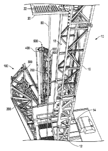
[044] FIG. 1 is an isometric view of an automatic pipe racking mechanism 100
including
features of the invention disclosed in U.S. Patent 9,091,128 (iss.
07/28/2015), and which
embodies a drill floor mounted structure of the type to which the present
inventive system
and method of raising applies. Drilling rig 10 has a drill floor 14 located
over a wellbore 12.
A drilling mast 16 is mounted to drill floor 14, which has an open V-door side
18. Racking
mechanism 100 is mounted on drill floor 14, on the V-door side 18 of drilling
mast 16.
[045] Racking mechanism 100 is comprised of a base frame 200 that is pivotally
connected
to drill floor 14 by floor pins 202. In one embodiment, base frame 200 is a
tapered C-frame
that extends upwards from drill floor 14 at a position offset to V-door side
18 of drilling
mast 16. A pipe handling mechanism 800 is extendable from base frame 200,
and capable of moving stands of connected pipe 50 from a racked position on
drill floor 14 to a stabbing position above a drill string component held in a
rotary table. A
mast brace 204 is connected between base frame 200 and
8
CA 02935843 2016-07-04
WO 2014/144995
PCT/US2014/029629
drilling mast 16 at a position distal to drill floor 14 for stabilizing an
upper end of base
frame 200 in relationship to drilling mast 16. In one embodiment, a pair of
tensioning
members 206 is connected between drill floor 14 and base frame 200.
[046] In one embodiment, the length of mast brace 204 is controllably
adjustable to
compensate for deflection of racking mechanism 100 under different payloads
which
vary with the size of the tubular being handled. Adjustment is also
advantageous to
accommodate non-verticality and settling of drilling rig 10. Adjustment is
also useful for
connectivity to other mechanisms that deliver or receive pipe from racking
mechanism
100. Adjustment is also useful when using mast braces 204 as a connected
lifting
component of the present raising system.
[047] FIG. 2 is an isometric view of base frame 200 of racking mechanism
100,
illustrating base frame 200 in isolation of the remaining components of
racking
mechanism 100 and of drilling rig 10. In one embodiment, base frame 200
includes a
pair of deployable legs 210 pivotally connectable at a lower end of base frame
200.
When legs 210 are deployed downward, deployed ends of legs 210 are connected
to drill
floor 14 (not shown) by floor pins 202. Retraction of legs 210 provides a
shorter
transport profile for transporting racking mechanism 100 between drilling
sites.
[048] Base frame 200 also includes a pair of deployable arms 212, pivotally
attached
to base frame 200. In one embodiment, when arms 212 are deployed outward,
deployed
ends of arms 212 are connected to base frame 200 by struts 214. In this
embodiment,
mast braces 204 are pivotally connected to the ends of arms 212, and pivotally
connectable to mast 16. This connectivity increases the spacing between mast
braces
204 and mast 16, providing conflict free mechanical operation of racking
mechanism
100. Retraction of arms 212 and pivotal retraction of braces 204 provides a
narrower
transport profile for transporting racking mechanism 100 between drilling
sites. In
another embodiment (best seen in FIG. 3), legs 210, arms 212 and braces 204
fully
retract without structural interference, such that each retracts proximate to
base 200 for
greater transportability. As shown in the present embodiment of base frame
200, an
optional bracket 216 may be provided for supporting mast braces 204 during
transport of
base frame 200. Bracket 216 may be attached to struts 214 or mast braces 204
to secure
these elements to the mast braces 204 during transport.
9
CA 02935843 2016-07-04
WO 2014/144995
PCT/US2014/029629
[049] Base frame 200 has a skid assembly 220 attached to the side opposite
mast 16.
In another embodiment, tensioning members 206 connect each side of base frame
200 to
drill floor 14 (not shown) of drilling rig 10 (not shown). Tensioning members
206
stabilize base frame 200 of racking mechanism 100. In one embodiment,
tensioning
members 206 are adjustable to stiffen racking mechanism 100, and to compensate
for
verticality and the variable deflection of racking mechanism 100 when handling
different
sizes of drill pipe 50.
[050] It will be appreciated that the disclosed invention, or a similar
automatic pipe
racking system, must be capable of rapid disassembly and assembly. In
contemporary
drilling operations, it is necessary to minimize the downtime of the drilling
rig and to
"rig down" or disassemble the entire drilling rig to a minimum number of
transportable
components as quickly as possible. The transportable components must fit
within
regulated physical dimensions for safe transport on designated highways to
remote
locations where the drilling activity can resume.
[051] FIG. 3 is an isometric representation of a transport vehicle 900
transporting
racking mechanism 100 to a position in alignment beneath mast 16. Drilling rig
10 has
its mast 16 assembled but not raised. Mast 16 is pivotally connected to a
substructure 30
that is also not raised. In the embodiment illustrated, mast 16 is optionally
supported by
a rack, such as a headache rack 40 for safety. In the embodiment illustrated
in this view,
base frame 200 has a skid assembly 220 attached.
[052] Skid assembly 220 supports racking mechanism 100 on transport vehicle
900.
During transportation, and as illustrated here, lower skid 228 and upper skid
226 support
racking mechanism 100 on the trailer bed 910 of transport vehicle 900.
Transport
vehicle 900 is maneuvered to position racking mechanism 100 beneath mast 16.
Alternatively, racking mechanism 100 may be placed on the ground on top of
skid
assembly 220 and positioned into place with equipment such as a fork lift.
[053] FIG. 4 is a continuation of the rig-up process illustrated in FIG. 3,
illustrating
deployment of components of racking mechanism 100 that were previously
retracted for
transportation as shown in FIG. 3. In particular, arms 212, mast braces 204,
and legs 210
have been deployed. Optionally, when arms 212 are deployed outward, deployed
ends
of arms 212 may be connected to base frame 200 by struts 214 to further
strengthen their
position.
CA 02935843 2016-07-04
WO 2014/144995
PCT/US2014/029629
[054] Also illustrated in FIG 4, lower skid 228 has been retracted, and a
jack 240
(FIG. 6) has been actuated to tilt racking mechanism 100 backwards over pivot
center
222 such that racking mechanism 100 is resting on retracted lower skid 228.
Upper skid
226 no longer supports the weight of racking mechanism 100, as the center of
gravity
224 of racking mechanism 100 has shifted below pivot center 222.
[055] In an optional embodiment, wheel assembly 242 is deployed when jack
240 is
actuated to facilitate minor realignment of racking mechanism 100 relative to
drill floor
14 as may be necessary.
[056] FIG. 5 is a close-up side view, illustrating the automatic pipe
racking
mechanism 100 resting on skid assembly 220 in the transport position on
trailer bed 910
of a transport vehicle 900.
[057] In the embodiment illustrated, skid assembly 220 has a skid ground
pivot 222
located proximate to where lower skid 228 is pivotally connected to base frame
200.
Ground pivot 222 is also located near the center of gravity 224 of racking
mechanism
100 when the automatic pipe racking mechanism 100 is resting on skid 220. In
this
embodiment, an upper skid portion 226 extends above ground pivot 222, and
lower skid
portion 228 extends below ground pivot 222.
[058] In this transport position, both lower skid 228 and upper skid 226
are in
contact with trailer bed 910 of transport vehicle 900. This configuration
provides for
stability during transport, as both lower skid 228 and upper skid 226 support
the weight
of racking mechanism 100 as transport vehicle 900 accelerates, decelerates and
navigates
turns, shifting the weight of racking mechanism 100 on trailer bed 910.
[059] In the embodiment illustrated, one or more skid stand-offs 230 are
pivotally
connected to lower skid portion 228 at pivot 232. Retractable stand-offs 230
are
pivotally connected to base frame 200 at pivots 234. Stand-offs 230 hold lower
skid 228
in the deployed position. Also seen in the embodiment illustrated, an optional
jack 240
is located proximate to the upper end of upper skid 226, opposite to the
ground pivot 222
end of upper skid 226.
[060] FIG. 6 is a general side view of the lower portion of base frame 200,
including
an exploded view of skid assembly 220 in accordance with an embodiment of the
present
invention. In this view, upper skid 226 is shown attached to base frame 200.
Lower skid
11
CA 02935843 2016-07-04
WO 2014/144995
PCT/US2014/029629
228 is shown detached from pivot 222. Stand-offs 230 are shown having wheels
246
attached, which are mostly hidden from view in the other figures.
[061] To transition racking mechanism 100 to a rig-up position, stand-offs
230 are
moved from the extended position to the retracted position, causing lower skid
228 to
retract into proximity with base frame 200. In the embodiment illustrated,
this
movement exposes wheels 246 beneath lower skid 228. This will permit wheels
246 to
engage trailer bed 910 to facilitate corrective alignment of racking mechanism
100 with
drill floor 14 and mast 16 if such alignment is necessary. Such engagement
will occur in
the next step of tilting.
[062] Still referring to FIG. 6, a jack 240 is attached to a jack frame 244
having a
wheel assembly 242 attached. To transition racking mechanism 100 to a rig-up
position,
jack 240 may be actuated, causing racking mechanism 100 to tilt onto wheels
242 of
retracted lower skid 228. In the embodiment illustrated, extension of jack 240
exposes
wheel assembly 242 beneath upper skid 226. This permits wheels 246 to engage
trailer
bed 910 to facilitate corrective alignment of racking mechanism 100 with drill
floor 14
and mast 16 if such alignment is necessary.
[063] FIG. 7 is a general side view, illustrating the automatic racking
mechanism
100 resting on skid assembly 220, with skid assembly 220 shown transitioning
from the
transport position to the rig-up position. In this intermediate step, stand-
offs 230 are
retracted, which retracts lower skid 228 about pivot 222 to a position closer
to base
frame 200. Since center of gravity 224 is located on the upper skid 226 side
of ground
pivot 222, racking mechanism 100 does not tip uncontrollably onto wheels 246
of lower
skid 228.
[064] FIG. 8 is a general side view, illustrating automatic racking
mechanism 100
resting on skid assembly 220, with skid assembly 220 shown in the rig-up
position. Jack
240 has been actuated so as to tilt racking mechanism 100 rearward until
wheels 246 of
lower skid 228 contact trailer bed 910. Additionally, wheel assembly 242 comes
into
engagement with trailer bed 910 to further facilitate corrective alignment of
racking
mechanism 100 with drill floor 14 and mast 16 if such alignment is necessary.
[065] FIG. 9 is a continuation of the rig-up process illustrated in FIG. 4,
and as
illustrated in FIGS. 5-8. FIG. 9 illustrates movement of transport vehicle 900
into
position closer to substructure 30. Tilted automatic racking mechanism 100 on
transport
12
CA 02935843 2016-07-04
WO 2014/144995
PCT/US2014/029629
trailer bed 910 is now in position for connection of the deployed components
of racking
mechanism 100 to drill rig 10.
[066] As seen in FIG. 9, by tilting racking mechanism 100, racking
mechanism 100
is now positioned such that legs 210 extend appropriately over drill floor 14
to align legs
210 for pivotal connection to drill floor 14 with floor pins 202. Mast braces
204 may
also be pivotally connected to mast 16 in this position. Optionally, a pair of
tensioning
members 206 are connected between drill floor 14 and base frame 200.
Tensioning
members 206 further stabilize base frame 200 in relationship to drilling rig
10.
Alternatively, tensioning members 206 may be connected after raising automatic
pipe
racking mechanism 100. Optionally, a frame support 40 such as the headache
rack, can
be positioned underneath mast 16 for safety.
[067] FIG. 10 is a continuation of the rig-up process illustrated in FIGS.
3-9. FIG.
illustrates transport vehicle 900 removed from beneath mast 16, and racking
mechanism 100 remains suspended by its connections to drill rig 10. When
transport
vehicle 900 departs, the racking board 20 can be attached to the mast 16 as
shown.
[068] FIG. 11 is a continuation of the rig-up process illustrated in FIGS.
3-10,
illustrating partial raising of mast 16 and automatic pipe racking mechanism
100 towards
a vertical position over drill floor 14. This step is conventionally performed
by extension
of hydraulic cylinders sized for the task. As mast 16 is raised, automatic
pipe racking
mechanism 100 is pulled into position by mast braces 204 through arms 212,
pivoting
automatic pipe racking mechanism 100 on the pivotal connection 202 of legs 210
to drill
floor 14 at floor pins 202. Tensioning members 206 are not shown connected
between
automatic pipe racking mechanism 100 and drill floor 14, but they may be
connected at
this time as well.
[069] FIG. 12 is a continuation of the rig-up process illustrated in FIGS.
3-11,
illustrating mast 16 and automatic pipe racking mechanism 100 in the vertical
position
above drill floor 14. Mast braces 204 are no longer supporting the weight of
automatic
pipe racking mechanism 100. In this position, the verticality of automatic
pipe racking
mechanism 100 can be adjusted by adjustment of mast braces 204.
[070] As described, the relationship of these elements has been shown to be
extremely advantageous in providing an automatic pipe racking mechanism 100
that can
be mounted to a conventional drill floor, and that is capable of lifting and
moving drill
13
CA 02935843 2016-07-04
WO 2014/144995
PCT/US2014/029629
pipe between a racked position within a largely conventional racking board and
a stabbed
position over a wellbore.
[071] Having
thus described the present invention by reference to selected
embodiments, it is noted that the embodiments disclosed are illustrative
rather than
limiting in nature and that a wide range of variations, modifications,
changes, and
substitutions are contemplated in the foregoing disclosure and, in some
instances, some
features of the present invention may be employed without a corresponding use
of the
other features. Many such variations and modifications may be considered
desirable by
those skilled in the art based upon a review of the foregoing description of
embodiments.
Accordingly, it is appropriate that the appended claims be construed broadly
and in a
manner consistent with the scope of the invention.
14