Note: Descriptions are shown in the official language in which they were submitted.
Title =
PISTON PUMP WITH LOCKING PISTONS.
= Scope of the Invention
[0001] This invention relates to a piston pump assembly having a piston-
forming element
coaxially mounted to a piston chamber-forming body for reciprocal axial
movement to
dispense product and in which the piston-forming element is movable between
locked
inoperative and unlocked operative positions by sequenced rotational and/or
axial movement
relative the piston chamber-forming body.
Background of the Invention =
[0002] Pumps for dispensing fluid product from containers are known to
include piston
pumps in which a piston is moved axially to discharge a fluid and in which the
piston may be
moved to a locked position in which the pump is inoperative as can be
advantageous during
. shipping or handling.
[0003] A number of disadvantages arise with known lockable piston pumps.
One
disadvantage is that With many known pumps, the piston inadvertently moVes out
a locked
= position in shipping. Another disadvantage is that during the use of many
known pumps,
upon moving the piston from a locked to an unlocked position, the pump does
not provide a
tactile feeling to a user by which the user may understand that the piston has
been moved
between locked and unlocked positions. Another disadvantage = with many known
pumps is
that a considerable number of components are required lo provide a locking
mechanism as
contrasted with pumps that do not include a locking mechanism. =
=
1
CA 2935908 2023-04-19
,
Summary of the Invention
[0004] To at least partially overcome some of these disadvantages of
known pumps, the
present invention provides a piston pump with an improved arrangement by which
a piston-
= forming element is movable relative to a piston chamber-forming element
between locked and
= unlocked positions. Preferably, in accordance with the present invention,
the piston chamber-
forming body has a collar member having an inner guide tube coaxially about an
axis with a
lug member extending radially inwardly therefrom and the piston-forming
element has a slide
tube coaxially radially inwardly of the collar member with the slide tube
carrying motion
= control features for interaction and engagement with the lug member
whereby relative axial
and rotational movement of the piston-forming element relative to the piston
chamber-
forming body, provides for the adoption of positions in which the pump is
operable to dispense
fluid and positions in which the pump is inoperative.
[0005] Preferably, the slide tube has a side wall that has
integrally formed therein a
resilient finger member disposed circumferentially between a stop slot and a
slide channel on
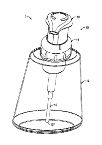
the slide tube such that with rotation of the piston-forming element to
appropriate axial
positions relative to the piston chamber-forming member, the lug member moves
between a
position in the stop slot in which the pump is rendered inoperative, and a
position in the slide
channel in which axial movement for operation of the pump is permitted.
= [0006] The finger member preferably is provided in the
slide tube as a resilient member
axially between two axially extending cut slots cut through the side wall of
the slide tube
. with the finger member extending between the cut slots to a distal inner
end.
= 2
CA 2935908 2023-04-19
=
[0007] Preferably, the provision of the finger member, the slide
channel and the stop slot
in the side tube wall reduces the number of components*requirdd for the pump.
[0008] In a first aspect, the present invention provides a liquid
pump for dispensing a liquid
from a container comprising:
[0009] a piston chamber-forming body having a cylindrical fluid
chamber disposed about
an axis and open at an axially outer end,
[0010] a piston-forming element comprising a piston member and an
actuator member,
[0011] the piston member extending from the actuator member
coaxially inwardly through
the outer end of the fluid chamber into the fluid chamber and engaging the
fluid chamber to
form a liquid pump, .
[0012] the piston-forming element including a central axially
extending stem with a
passageway therethrough for passage of the liquid discharged by the liquid
pump axially
outwardly to a discharge outlet on the actuator member axially outwardly of
the piston
chamber-forming body,
= [0013] wherein in coaxial reciprocal movement of the piston-
forming element relative the
piston chamber-forming body about the axis between a retracted axial position
and an extended
axial position, the liquid pump dispenses liquid from the container out the
discharge outlet 36,
[0014] the piston chamber-forming body including a collar member for
engagement with
= an opening
of the container, =
[0015] the collar member having an inner guide tube coaxially about
the axis open at both
an axially inner end and an axial outer end, the guide tube having a
cylindrical radially
inwardly directed inner guide surface,
= 3
CA 2935908 2023-04-19
= [0016] a lug member extending radially inwardly from the
inner guide surface,
[0017] the lug member extending radially inwardly from the inner guide
surface over a
circumferential extent C, a radial extent R, and an axial extent A,
= [0018] the piston-forming element having an outer slide tube fixed
to the actuator member
at an axially outer end and extending axially inwardly to an open axial inner
slide tube end,
. [0019] the slide tube coaxially about the piston member radially
outwardly about the piston
member,
[0020] the slide tube having a radially outwardly directed outer tubular
slide tube wall,
== [0021] a pair of axially extending circumferentially spaced cut slots,
each cut radially
through the slide tube wall from a respective inner slot end open to the inner
slide tube end to a
respective blind outer slot end located spaced axially outwardly from the
inner slide tube end,
= [0022] a first finger member defined in the slide tube
wall between the cut slots with the
= first finger member extending from an axially inner distal end of the
first finger member to an
axially outer end of the first finger member where the first finger member
merges into the slide
tube wall between the outer slot ends,
[0023] the first finger member deflectable by radially inwardly directed
forces to move the
distal end radially inwardly relative the slide tube wall,
[0024] the slide tube having an axially extending first slide channel
extending radially
inwardly from the slide tube wall,
[0025] = the first slide channel and the lug member complementarily sized in
circumferential
extent and radial extent such that when the slide tube is rotated about the
axis relative the guide
tube to a first operative rotational position, the lug member slides axially
in the first side
4
CA 2935908 2023-04-19
,
channel permitting relative coaxial sliding between the retracted position and
the extended
position for operation of the liquid pump to dispense the liquid,
[0026] the slide tube having an axially extending first stop slot
extending radially inwardly
into the slide tube wall,
= [0027] the first stop slot and the lug member complementarily
sized in circumferential
extent and radial extent such that when the slide tube is rotated about the
axis relative the guide
' tube to a first inoperative rotational position, the lug member is
received in the first stop slot and
engageMent between the slide tube and the guide tube limits relative coaxial
sliding to prevent
operation of the liquid pump to dispense the liquid,
[0028] the first finger member located on the slide tube
circumferentially between the first
" slide channel and the first stop slot,
= [0029] in relative rotation of the guide tube and the slide tube
about the axis from the first
inoperative rotational position to the first operative rotational position,
the first finger member
blocks the circumferential movement of the lug member until with relative
rotation about the
axis, a camming surface of the lug member and a cartuned surface on the first
finger member
engage deflecting the first finger member radially inwardly out of the path of
the lug member
permitting the lug member to rotate circumferentially therepast from the first
inoperative
rotational position to the first operative rotational position.
Brief Description of the Drawings =
[0030] Further aspects and advantages of the present invention will
occur from the
. following description taken together with the accompanying drawings in
which:
CA 2935908 2023-04-19
=
= A
[0031] Figure 1 is a pictorial view of a fluid dispenser with a
pump assembly in
= accordance with the present invention in a locked condition;
= [0032] Figure 2 is a pictorial view of the dispenser of Figure. 1
with the pump assembly
in an unlocked extended position;
[0033] Figure 3 is a pictorial view of the dispenser of Figure 1
with the pump assembly
in an unlocked retracted condition;
[0034] Figure 4 is a cross-sectional side view through the
dispenser of Figure 2 along
= section line A-A' including a central axis through the pump assembly;
[0035] Figure 5 is an enlarged cross-sectional side view of the
pump assembly as shown
in Figure 4;
[0036] Figure 6 is a cross-sectional side view same as Figure 5,
but showing the pump
. assembly in the retracted position as in Figure 3;
= [0037] Figure 7 is a pictorial view with a collar member ofthe
pump assembly in Figure
4;
[0038] Figure 8 is a pictorial cross-sectional view along section
line A-A' in Figure 2 of a
tube member of the piston chamber-forming body of the pump assembly of Figure
4;
[0039] Figure 9 is a cross-sectional side view of the piston
chamber-forming element as
= seen in Figure 4;
[0040] = Figure 10 is a cross-sectional side view of the piston-forming
element as seen in
Figure 4;
[0041] Figure 11 is a pictorial cross-sectional side view along
section line A-A' in Figure
2 of the piston member of the piston chamber-forming body shown in Figure 10;
=
6
CA 2935908 2023-04-19
,
[0042] Figure 12 is a pictorial cross-sectional side view along
section line A-A' in Figure
2 of the actuator member of the piston-forming element shown in Figure 10;
[0043] Figure 13 is a pictorial rear view of the actuator member
of Figure 12 as seen
from above;
[0044] Figure 14 is a pictorial right side view of the Actuator
member of Figure 12 as=
seen from below;
[0045] Figure 15 is a pictorial rear view of the actuator member
of Figure 12 as seen
from below;
[0046] Figure 16 is a pictorial bottom view showing merely the
collar member coupled to
the actuator member in the locked condition of Figure 1;
[0047] Figure 17 is a cross-sectional side view through Figure 16
along section plane B-B'
in Figure 16 including the central axis through the pump assembly;
[0048] Figure 18 is a pictorial cross-sectional view of the collar
member and actuator
member of Figure 16 along section line C-C' in Figure 17;
, [0049] Figure 19 is a pictorial bottom view similar to Figure 16,
but showing the collar
member and the actuator member in the unlocked retracted condition of Figure
2;
[0050] Figure 20 is a cross-sectional top view along section line
D-D' in Figure 17
showing the pump in a unlocked extended position as in Figure 2, however, with
the chamber
member and the spring member, not shown;
. [0051] = Figure 21 is a view the same as Figure 20 but with the pump in the
locked
= extended position as in Figure 1;
7
CA 2935908 2023-04-19
= [0052] Figure 22 is a view the same as Figure 21 but in which the
actuator member has
been rotated clockwise relative to the collar member so as to increase an
angular position
indicated as A in Figure 21 to an angular position indicated as B in Figure
22;
= [0053] Figure 23 is a view the same as Figure 22 but in which the
actuator member has
been rotated clockwise relative to the collar member so as to increase an
angular position
indicated as B in Figure 22 to an angular position indicated as C in Figure
23;
[0054] Figure 24 is a view the same as Figure 20 but showing a
second embodiment of a
pump assembly in accordance with the present invention;
[0055] Figure 25 is a cross-sectional side view the same as Figure
5, but showing a pump
assembly in accordance with a third embodiment of the present invention;
[0056] Figure 26 is a pictorial right side view, of an actuator
member as seen from below
for a fourth embodiment of a pump assembly in accordance with the present
invention;
[0057] Figure 27 is a perspective view of a fluid dispenser with a
pump assembly in
accordance with a fifth embodiment of the present invention in an unlocked
extended
position;
[0058] Figure 28 is a pictorial right side view of the actuator
member as seen from below
= for the fifth embodiment of the pump assembly and dispenser shown in
Figure 27;
[0059] Figure 29 is cross-sectional side view through Figure 28
along section plane E-E';
[0060] Figure 30 is a perspective view of a fluid dispenser with a
pump assembly in
accordance with a sixth embodiment of the present invention in an unlocked
extended
position;
= 8
CA 2935908 2023-04-19
= , s,
[0061] Figure 31 is a pictorial rear view of the actuator member
as seen from below for
the sixth embodiment of the pump assembly and dispenser shown in Figure 30;
[0062] Figure 32 is cross-sectional side view through Figure 31
along section plane G-G';
[0063] Figure 33 is a perspective view of a fluid dispenser with
a pump assembly in
accordance with a seventh embodiment of the present invention in an unlocked
extended
= position;
[0064] Figure 34 is a pictorial right side view of the actuator
member as seen from above
for the seventh embodiment of the pump assembly and dispenser shown in Figure
33; and
= [0065] Figure 35 is a pictorial rear view of the actuator member
of Figure 34 as seen
from below.
Detailed Description of the Drawings
[0066] Reference is made to Figures 1 to 23 showing a first
embodiment of a dispenser 9
in accordance with the present invention. The dispenser 9 includes a pump
assembly 10 and
a container 12. In Figures 1, 2 and 3, for ease of illustration, the container
12 is illustrated as
being transparent.
[0067] The container 12 is enclosed but for an opening 37, as
seen in Figure 4, provided
at an axially outer end of a threaded neck 101 of the container which is
coupled to a top wall
102 of the container 12. The top wall 102 merges into a side wall 103 and,
hence, into a
bottom wall 104. As illustrated in Figure 4, a liquid 105 is contained within
the container 12
and the pump assembly 10 is adapted to discharge the liquid 105 from container
12.
[0068] As seen in the cross-section of Figure 4, the pump
assembly 10 has a piston
= chamber-forming body 14 and a piston-forming element 16. Each of the
piston chamber-
= 9
CA 2935908 2023-04-19
forming body 14 and the piston-forming element 16 are substantially disposed
coaxially about
a central axis 20. When the pump assembly 10 is in an unlocked configuration,
coaxial
reciprocal movement of the piston-forming element 16 relative the piston
chamber-forming
body 14 about the axis 20 between an axially extended position as shown in
Figures 2, 4 and 5
and an axially retracted position shown in Figures 3 and 6, dispenses the
liquid 105 from the
container 12 out a discharge outlet 36 of the piston-forming element 16.
[0069] The piston chamber-forming body 14, as seen in Figures 5 and 9,
comprises two
major components, a collar member 38 and a tube member 39 which are fixedly
secured
together in a snap fit relation. The piston-forming element 16 includes as two
lesser elements a
one-way inlet valve 17 and a dip tube 19.
[0070] The tube member 39 has a side wall 106 disposed coaxially about
the axis 20 with a
generally stepped configuration so as to define an axially inner fluid chamber
18 and an axially
outer air chamber 118.
[0071] The fluid chamber 18 is defined inside the wall 106 from an
axially inner end 119
to an axially outer end 120 of the fluid chamber 18. The axially inner end 119
is defined by a
radially inwardly extending shoulder 121 with an inlet opening 122 coaxially
therethrough
opening axially inwardly into a socket 123 open axially inwardly. The socket
123 is adapted to
frictionally receive an inner end of the dip tube 19. The hollow tubular dip
tube= 19 extends
downwardly to a lower end .107 disposed approximate the bottom wall .104 of
the container 12.
= The one-way inlet valve 17 is secured in the inlet opening 122 in a snap
fit and includes a
resilient disc 124 that engages the radially inwardly directed inner surface
of the wall 106 to
permit fluid flow axially outwardly therepast yet to prevent fluid flow
axially inwardly
=
CA 2935908 2023-04-19
therepast as in a manner, for example, described in a similar one-way inlet
valve in U.S. Patent
No. 5,676,277 to Ophardt issued October 14, 1997. The fluid chamber 18 is open
at its axially
outer end 120 into an inner end 125 of the air chamber 118. The air chamber
118 is defined
= within the wall 106 between its axially inner end 125 and an axially
outer end 130. Thus, the
fluid chamber 118 is open at its axially inner end 120 into the air chamber
118. The air
chamber 118 is open axially outwardly at its axially outer end 130. The fluid
chamber 118 is
defined between its axially inner end 119 and its axially outer end 120
radially inwardly of an
inner portion 131 of the wall 106 which is circular in cross-section,
substantially cylindrical
and has a diameter. The air chamber 118 is defined between its axially inner
end 125 and its
axially outer end 130 by an outer portion 132 of the wall 106 which is
circular in cross-section,
substantially cylindrical and has a diameter larger than the diameter of the
inner wall portion
131 forming the fluid chamber 18. As best seen in Figure 8, the wall 106
carries at the outer
end 130 a radially outwardly extending snap flange 135 and spaced axially
inwardly from the
snap flange 135, a radially outwardly extending sealing flange 134.
[0072] As seen in Figures 5 and 9 the Collar member 38 is secured
in a fixed snap fit
relation on to the axially outer end 130 of the tube member 39. The collar
member 38 has an
inner guide tube 40 Coaxially about the axis 20. The inner guide tube 40 is
open both at an
axially inner end 41 and an axially outer end 42. The guide tube 40 has a
cylindrical radially
inwardly directed inner guide surface 44 extending between its inner end 41
and its outer end
42. The collar member 38 includes a radially outwardly extending shoulder
flange 140
merging into an outer collar tube 142 having a threaded radially inwardly
directed surface 143
= carrying threads for engagement with complementary threads on the
threaded neck 101 of the
= = 11 CA 2935908 2023-04-19
1.
container 12. Between the inner guide tube 40 and the outer collar tube 142,
an axially
extending snap tube 144 extends axially inwardly from the shoulder flange 140.
As seen in
Figure 9, the snap tube 144 on the collar member 38 carries an axially
inwardly directed
shoulder for engagement with an axially outwardly directed shoulder, on the
snap flange 135 of
the wall of the tube member 39 to fixedly secure the collar member 38 and the
tube member 39
coaxially about the axis 20 with the inner guide tube 40 disposed radially
inwardly of the wall
106 of the tube member 39 about the outer end 130. As can be seen in Figure 4,
the collar
member 38 is secured to the container 12 with the threaded surface 143 of the
collar member
38 engaging the threaded neck 101 on the container 12 and urging the sealing
flange 134 of the
tube member 38 into sealed engagement with the opening 37 of the container 12,
preferably
with a resilient annular gasket member 200 disposed axially therebetween.
[0073]
Referring to Figure 7 showing the collar member 38, the inner guide
tube 40 carries
a lug member 46 that extends radially inwardly from the inner guide surface
44. The lug
= member 46 as seen in Figure 7 has an axially outwardly directed outer
axial lug stop surface
218, an axially inwardly directed inner axial lug stop surface 219, a
circumferentially directed
right lug side surface 220, a circumferentially directed left lug side surface
222, and a radially
inwardly directed circumferential lug surface 223. The lug member 46 provides
as curved
merger of the right lug side surface 220 and the circumferential lug surface
223, a camming
surface 78. The lug member 46 is marked on Figure 7 to extend radially
inwardly from the
inner guide surface 44 over a circumferential extent C between the right lug
side surface 220
and the left lug side surface 222, a radial extent R from the inner, guide
surface 44 to the
12
CA 2935908 2023-04-19
circumferential lug surface 223 and an axial extent A between the outer axial
lug stop surface
218 and the inner axial lug stop surface 219.
[0074] Reference is made to Figures 10 to 12 showing the piston-
forming element 16 as
comprising two major elements, namely, a piston member 24 and an actuator
member 26. In
addition, as a minor element, the piston-forming element 16 includes a foam
generator 25
schematically illustrated in Figure 11.
[0075] The foam generator 25 is schematically illustrated as a
cylindrical member
comprising a pair of spaced screens 601, 602 bonded to the axial ends of a
cylindrical porous
sponge-like plug. The particular nature of the foam generator 25 is, however,
not limited. The
= foam generator 25 is adapted to be received within a passageway 34
axially inwardly from an
end cap 170 on the actuator member 26 and supported on a radially outwardly
directed
shoulder within the passageway 34. The particular nature of a foam generator
25 is not limited
and the purpose of the foam generator is to generate a consistent mixture of a
foamed air and
liquid product on simultaneous passing of the air and liquid therethrough.
= [0076] The piston member 24 is best seen by itself in Figure 11 as
being disposed coaxially
about the axis 20. The piston-forming element 16 includes a central axially
extending stem 32
with the passageway 34 therethrough closed at an axially inner end 150 and
open at an axially
= outer end 151. The piston member 24 carries a reduced diameter axially
innermost fluid piston
portion 152 which is adapted to be coaxially received within the fluid chamber
18 to form a
liquid pump 30. The fluid piston portion 152 includes a resilient inner disc
153 that engages
the side wall 106 in the fluid chamber 118 to permit fluid flow axially
outwardly therepast but
= to prevent fluid flow axially inwardly therepast. The fluid piston
portion 152 includes an outer
= 13 .=
=
CA 2935908 2023-04-19
disc 154 that engages the side wall 106 in the fluid chamber 18 to prevent
fluid flow axially
therepast. Liquid ports 155 located on the stem 32 between the outer disc 154
and the inner
disc 153 extend coaxially through the stem 32 into the passageway 34. With
reciprocal coaxial
= Movement of the piston member 24 relative to the tube member 39, the
fluid 105 is drawn
upwardly from the container 12 though the dip tube 19 past the one-way inlet
valve 17 into the
. fluid chamber 18 in a retraction stroke and in an opposite extension stroke,
the fluid 105 is
discharged axially outwardly past the inner disc 153 into an annular space 149
radially outward
of the stem 32 and radially inward of the wall 106 and between the inner disc
153 and the outer
= disc 154 and hence via the liquid ports 155 radially through the stem 32
into the passageway 34
leading to the discharge outlet 36. The operation of the liquid pump 30 is
substantially the=
same as described in U.S. Patent 5,676,277 to OphamIt referenced above.
However, many
other configurations of a piston pump may be adopted for the liquid pump 30
without departing
from the present invention.
[0077]
In the liquid pump 30, there is defined between the outer disc 154
and the one-way
inlet valve 17, a liquid compartment 401 with a volume that varies with the
axial position of
the piston member 24 within the fluid chamber 18.
= [0078] I Axially outwardly on the stem 32 from the outer disc 154,
transfer ports 156 are
provided radially through the stem 32 into the passageway 34. Axially
outwardly from the
transfer ports 156, an annular air disc 157 extends radially outwardly from
the stem 32. The air
disc 157 extends radially from stem 32 at an axially outer end 174 of the air
disc 157 as a radial
shoulder 175 that bridges between the stem 32 and a generally cylindrical
tubular portion 176
of the air disc 157. The tubular portion 176 extends coaxially about the axis
20 from the radial
= 14
CA 2935908 2023-04-19
=
shoulder 175 axially inwardly to merge with at an axially inner end with the
radially outwardly
flange 177 carrying disc arms 161 and 162.
[0079] As can be seen in Figure 5, the air disc 157 at its radial
outer end carries the pair of
resilient disc arms 161 and 162 which engage the inner surface of the wall 106
inside the air
chamber 118 to provide a seal preventing flow axially inwardly or outwardly
therepast.
[0080] , An air compartment 402 is defined annularly about the stem 32
radially between the
stem 32 and the wall 106 about the air chamber 118 and axially between the air
disc 157 and
the outer disc 154. The air compartment 402 has a volume that varies with the
axial position of
the piston member 24 within the tube member 39 whereby an air pump 31 is
formed. In a
retraction stroke, the volume of the air compartment 402 decreases forcing air
through the
= transfer ports 156 into the passageway 34 simultaneously with the
discharge of the liquid 105
from the pump liquid 30 into the passageway 34 for simultaneous discharge of
air and liquid
via the passageway 34 through the foam generator 25 to produce a foam of air
and the liquid
that is discharged to the discharge outlet 36. In a withdrawal stroke, the
volume of the air
compartment 402 increases drawing via the discharge outlet 36 air from the
atmosphere, as
well as drawing any foam, air or liquid within the passageway 34 into the air
compartment 402.
[0081] A spring member 15 is disposed with the air chamber 118
engaged at an axially
inner end of the spring member 15 on a radially extending shoulder 158 between
the outer end
120 of the fluid chamber 18 and the inner end 125 of the air chamber 118 and
at an axially
inner end and at an axially outer end of the spring member 15 on the radial
shoulder 175 of the
air disc 157. The spring member 15 biases the piston member 24 and thereby the
piston-
forming element 16 axially outwardly relative to the piston chamber-forming
body 14 to the
CA 2935908 2023-04-19
extended position as shown in Figure 5 and is compressible to permit the
piston-forming
element 16 to be moved relative the piston chamber-forming body 14 from the
extended
position of Figure 5 to the retracted position of Figure 6.
[0082] Reference is made to Figure 12 showing the actuator member 26
alone. The
actuator member 26 includes at an axially outer end the radially extending end
cap 170 from
which an outer slide tube 48 extends axially inwardly from an axially outer
end 49 of the outer
slide tube 48 to an open axially inner slide tube end 50. The slide tube 48
extends coaxially
about the .axis 20 axially inwardly from the end cap 170. An inner stem tube
171 also extends
coaxially about the axis 20 from the endcap 170 coaxially within the outer
slide tube 48 to an
axially inner end 172 of the inner stem tube 171. The actuator member 26
carries a radially
outwardly extending discharge tube 96 that extends radially outwardly from the
end cap 170
and carries the discharge outlet 36 at a radially outer end 97. An internal
passage 98 extends
= radially through the discharge tube 96 to provide for communication
between the discharge
outlet 36 and the passageway 34 in the stem 32.
[0083] As can be seen in Figure 10, the piston member 24 and the
actuator member 26 are
fixedly secured together with the inner stem tube 171 coaxially within the
open outer end of
the passageway 34 of the stem 32 of the piston member 24 in frictional
engagement. The end
cap 170 of the actuator member 26 provides an axially outer end of the
actuator member 26 as
an axially outwardly directed engagement surface 93 for the application of
manual forces to
move the piston-forming element 16 relative the piston chamber-forming body 14
axially from
the extended position as seen in Figure 5 to the retracted position such as
seen in Figure 6.
16 =
CA 2935908 2023-04-19
=
[0084] As can be seen in Figures 5 and 9, an air port 146 is
provided radially through the
wall 106 into the air chamber 118. Reference is made to Figure 4 which
illustrates the air port
146 as open on a radial outward side of the tube member 36 via an annular
passageway 173
= between the tube member 39 and the neck 101 of the container 12 into the
interior of the
container 12. When the Piston-forming element 16 is in an extended position as
seen in
Figures 4 and 5, the disc arms 161 and 162 on the air disc 157 overly the air
port 146 and
prevent flow through the air port 146. However, on the piston-forming element
16 being
= moved axially inwardly relative to the piston chamber-forming body 14
from the extended
= position of Figures 4 and 5, once the disc arm 162 on the air disc 157 is
moved axially
inwardly of the air port 146, then the radial inward side of the air port 146
is open to
atmospheric air via axially extending annular spacings between the slide tube
48 of the actuator
= member 26 and each of the side wall 106 of the tubular member 29 and the
inner guide tube 40
of the collar member 38. This communication of the air port 146 with the
atmosphere provides
for equalization of pressure between the atmosphere and the interior of the
container 12 as will
relieve any vacuum which may be developed in the interior of the container 12
due to the
= removal of the fluid 105 from the container 12 by the liquid pump 30.
[0085] Reference is made to Figures 12, 13, 14 and 15 showing the
actuator member 26
alone. As can be seen in Figure 12, the actuator member 26 carries the slide
tube 48 which has
a radially outwardly directed outer tubular slide tube wall 52 and a radially
inwardly directed
inner tubular slide tube wall 53. The outer slide tube wall 52 is circular in
any cross-section
normal the axis 20. Similarly, the inner slide tube wall 53 is circular in any
cross-section
normal the axis 20. The slide tube 48 carries approximate its inner slide tube
end 50 a radially
= 17
CA 2935908 2023-04-19
outwardly extending annular end flange 202 presenting an axially outwardly
directed stop
shoulder. 204.
[0086] , As can be best seen, for example, in Figures 17 and 18, the
engagement of the stop
shoulder 204 on the slide tube 48 with the axially inner end 41 of the inner
guide tube 40 of the
collar member 38 limits axial outward sliding of the actuator member 26
relative to the collar
member 38 and, hence, as seen in Figures 4 and 5, limits the axial outward
sliding of the
piston-forming element 16 relative the piston chamber-forming body 14 in the
extended
position. As seen in the left-hand side of Figure 17, the outer tubular side
wall 52 of the slide
tube 48 is in close relation to the radially inwardly directed inner guide
surface 44 of the inner
guide tube 40 on the collar Member 38 so as to journal the actuator member 26
coaxially in the
collar member 38 for both rotation about the axis 20 and coaxial sliding. If;
hypothetically, the
outer slide tube 48 and its radially outwardly directed outer tubular side
wall 52 as well as the
= inner guide tube 40 and its radially inwardly directed inner guide
,surface 44 were 360 about
their entire circumference to have the appearances seen in the left-hand side
of Figure 17, then
the actuator member 26 would freely coaxially slide relative to the collar
member 38 and the
= actuator member 26 would freely rotate relative to the collar member
about the axis 20. This is
not the case, however, as the lug member 46 carries on the collar member 38
and extending
radially inwardly from the inner guide surface 44 of the collar member 38
interacts with
various motion control features provided on the slide tube 48 of the-actuator
member 26.
These motion control features on the slide tube 48 include, as seen in Figure
15, an axially
extending slide channel 70, a stop slot 72 and a finger member 62.
=
18
CA 2935908 2023-04-19
f00871 The axially extending slide channel 70 is provided on the slide tube
48 to extend
radially inwardly from the outer tubular side tube wall 52 of the slide tube
48. The slide
channel 70 is defmed between two channel side walls 206 and 208 bridged by a
channel base
210. The slide channel 70 open radially outwardly over a circumferential
extent between the
side walls 206 and 208. The channel base 210 has a radially outwardly directed
base surface
211 and a radially inwardly directed base surface 212. The slide channel 70
has a radially
extent measured from the base surface 211 to a radius about the axis 20 in
which the outer
tubular slide tube wall 52 lies. The slide channel 70 is open at an axially
inner end 220 at the
inner slide tube end 50. The slide channel is closed at an axially outer end
wall 221. While the
actuator member 26 is in an operative rotational position relative to the
collar member 38, the
lug member 46 is received within the slide channel 70, which condition arises
in the unlocked
conditions of Figures 2 and 3 in which the lug member 46 is axially slidable
within the slide
channel 70 permitting reciprocal axial movement of the actuator member 26
between the
retracted position of Figure 2 and the extended position of Figure 3. The lug
member 46 has its
circumferential extent C and radial extent R complementary to the
circumferential extent and
radial extent of the slide channel 70 so as to provide for relative axial
sliding of the lug
member 46 within the slide channel 70.
[0088] The stop slot 72 is provided on the slide tube 48 to extend radially
inwardly from
the outer slide tube wall 52 of the slide tube 48. The stop slot 72 as best
seen in Figure 15 is
cut entirely through the slide tube 48. The stop slot 72 is bordered by a
circumferentially and
radially extending axially outer axial slot stop surface 213 and with the stop
slot 72 extending
circumferentially between a radially and axially extending left slot side
surface 214 and an
19
CA 2935908 2023-04-19
=
axially extending right slot side surface 216. The stop slot 72 extends
circumferentially
between the left slot side surface 214 and the right slot side surface 216
axially from the axial
slot stop surface 213 axially inwardly to an axially inner slot opening 217
into the stop slot 72
at the inner side tube end 50. The stop slot 72 has a circumferential extent
between the left slot
side surface 214 and the right slot side surface 216 and an axial extent
between the axial slot
stop surface 213 and the inner slot opening 217. The slide stop 72 also has a
radial extent.
[0089] When the actuator member 26 and the collar member 38 are in an
inoperative
rotational position such as in Figures 1, 16, 17 and 18, the collar member 38
is coaxially about
the actuator member 26 and the lug member 46 extends radially inwardly from
the collar
member 38 engaged within the stop slot 72 on the slide tube 48 of the actuator
member 26. In
this regard, the lug member 46 and the stop slot 72 are complementary sized as
to their
respective circumference extents C and radially extents R and axial extents A
respectively such
that the lug member 46 is be received within the stop slot 72. With the lug
member 46
received in the stop slot 72: (a) engagement between the axially outwardly
directed outer
axial lug stop surface 218 on the lug member 46 and the axial slot stop
surface 213 of the stop
slot 72 limits axial sliding of the lug member 46 within the stop slot 72
axially outwardly; (b)
engagement between the right lug side surface 220 of the lug member 46 with
the right slot
side surface 216 of the stop slot 72 prevents'relative rotation of the
actuator member 26 and the
collar member 36 in one direction about the axis 20; and (c) engagement of the
left lug side
surface 222 of the lug member 46 with the left slot side surface 214 of the
stop slot 72 restricts
relative rotation of the actuator member 26 and the collar member 38 about the
axis 20 in an
Opposite direction.
CA 2935908 2023-04-19
[0090] In the inoperative rotational position with the lug member 46
of the collar member
38 received within the stop slot 72 of the actuator member 26, then a locked
condition arises as
illustrated in Figures 16, 17, 18 and 21.
[0091] The finger member 62 is provided on the slide tube 48 as a
portion of the slide tube
wall 52 between a pair of cut slots 54 and 55. Each of the cut slots 54 and 55
extends radially
through the side wall tube 52 radially between the outer tubular slide tube
wall 52 and the inner
tubular slide tube wall 53. Each cut slot 54 and 55 extends axially from a
respective axial inner
slot end 56 and 57 open to the inner slide tube end 50 to a respective blind
axial outer slot end
* 60 and 61 located spaced axially inwardly from the inner slide tube end 50.
As best seen in
Figure 13, the cut slot 55 is provided as cut from the channel side wall 206
of the slide channel
=
70. The cut slot 54 is defined by the combination of the stop slot 72 and an
axially outer slot
portion 217 that extends axially outwardly from the stop slot 72. The finger
member 62 is
defined in the slide tube 48 circumferentially between the cut slots 54 and
55. The finger 62
extends from an axially. inner distal end 64 of the finger member 62 to an
axially outer end 66
of the finger member 62, where the finger member. 62 merges into the slide
tube wall 52
between the blind axial outer slot ends 60 and 61. As can be seen in Figure 3,
the blind axial
= outer slot ends 60 and 61 are spaced axially outwardly from the inner
slide tube end 50 an
equal distance. The finger member 62 has a radially outwardly directed outer
surface 224 that
is concave mirroring the curvature of the outer tubular side wall 52 and a
radially inwardly
directed inner surface 225 that is convex and mirroring the curvature of the
inner tubular side
= wall 53. The finger member 62 has a left side surface 226 that includes
the right slot side
surface 216 and on the opposite side a right side surface 227.
21
CA 2935908 2023-04-19
=
=
[0092] The slide tube 48 is provided such that the finger member 62
is a resilient member =
that is deflectable by radially inward directed forces to move the distal end
64 the finger
member 62 radially inwardly relative the slide tube wall 52. The finger member
62 is resilient
= and has an inherent bias to assume an unbiased condition as shown in
Figures 13 to 15
conforming to the circular in cross-section shape of the slide tube 48. When a
radially
inwardly directed force is applied to the finger member 62 as schematically
illustrated by the -
arrow F on Figure 13, the finger member 62 deflects with movement of the
distal end 64 of the
fmger Member 62 radially inwardly relative the outer end 66 and, on release of
such force F,
the finger member. 62 under its inherent bias moves towards its unbiased
condition. The slide
tube 48 is preferably made from materials having some inherent resiliency,
preferably by
= injection molding as a unitary element from plastic materials. Suitable
resiliency of the finger
member 62 may be provided by the selection of the materials from which the
slide tube 48 is
made.
[0093] The right slot side surface 216 of the stop slot 72 comprises
a portion of the left side
surface 226 of the finger member 62 within the stop slot 72. The tight 'slot
side surface 216
includes a cammed surface 80 which, while extending axially, is "beveled" so
as to extend at
an acute angle to an axially and 'radially extending plane including the axis
20 with a distance
of any point on the cammed surface 80 increasing in circumferential distance
from the left slot
= side surface 214 with increased radius from the axis 20.
[0094] Each of Figures 16 to 19 are illustrations showing merely the
actuator member 26
and the collar member 38 as coupled together and in which other components
forming the
pump assembly 10, not shown. Each of Figures 20 to 23 are illustrations
showing merely the
22
CA 2935908 2023-04-19
piston member 24, actuator member 26 and the collar member 38. Each of Figures
20 to 23
are cross-sectional views along section line D-D' in Figure 17 in the extended
position but with
the piston member 24 and actuator member 28 as the piston-forming element 16
in different
rotational positions about the axis 20 relative the collar member 38.
[0095] Reference is made to Figures 16, 17, 18 and 21 which
illustrate the actuator
member 26 and the collar member 38 coupled together in the locked condition
and the .
inoperative rotational position. In these Figures, under the bias of the
spring member 15 (not
shown) urging the actuator member 26 axially outwardly relative to the collar
member 38, the
outer axial lug stop surface 218 of the lug member 46 engages with the axial
slot stop surface
= 213 of the stop slot 72 to limit coaxially outward sliding of the
actuator member 26 relative to
the collar member 38 thereby preventing operation of the liquid pump 30 and
the air pump 31
to dispense the liquid and air. As best seen in Figure 21, but also in Figure
16, the left lug side
surface 222 of the lug member 46 engages the left slot side surface 214 of the
stop slot 72 to
prevent rotation of the actuator member 26 clockwise relative to the collar
member as seen in
Figure 21. On Figure 21, an angular vector A is indicated as the angle of
rotation about the
axis 20 between the left lug side surface 222 it'd the left slot side surface
214 as effectively nil.
In use, from the positions of Figure 16 and 21 the actuator member 26 is
manually rotated
counterclockwise relative to the collar member 38 until the right lug side
surface 220 of the lug
member 46 first engages the right slot side surface 216 with the camming
surface 78 on the lug
member 46 first engaging the cammed surface 80 of the finger member 62 and
assume the
positions of Figures 18 and 22 in which, as seen in Figure 22, the angular
vector B about the
= axis between the left lug side surface 222 and the left slot side surface
214 is marginally
23
CA 2935908 2023-04-19
= =
increased over angular vector A in Figure 21. From the position illustrated in
Figure 22, on
manual forces being applied to the actuator member 26 to rotate the actuator
member 26
counterclockwise relative to the collar member 38, the camming surface 78 of
the lug member
46 and the cammed surface 80 on the finger member 62 engage applying radially
inwardly
directed forces to the finger member 62 deflecting the finger member 62
radially inwardly out
of the path of the lug member 46 and permitting lug member 46 to rotate
circumferentially
counterclockwise radially outwardly past the deflected finger member 62 as
illustrated in
Figure 23 to have an angular vector C between the left lug side surface 222
and the left slot
side surface 214 increased over the angular vector B in Figure 22. As seen in
Figure 23, the
radially inwardly directed circumferential lug surface 223 of the lug member
46 is engaged
with the radially outwardly directed outer surface 224 of the finger member 62
to keep the
== finger member 62 deflected.
[0096]
From the position illustrated in Figure 23, with subsequent relative
manual rotation
of the actuator member 26 counterclockwise relative to the collar member 38,
the lug member
46 comes to move circumferentially past the finger member 62 and become
disposed within
the slide channel 70 with counterclockwise movement of the actuator Member 26
relative to
the collar member 38 stopped with the right lug side surface 220 of the lug
member 46
engaging the channel side wall 208 as seen in Figure 20. As seen in Figure 20,
the angular.
vector D between the left lug side surface 222 and the left slot side surface
214 has increased
over the angular vector C of Figure 23. As seen in Figure.20, the lug member
46 has moved
counterclockwise past the finger member 62 and the finger member 62 under its
inherent bias
has moved radially outwardly from the defected condition shown in Figure 23
towards the
=
24
CA 2935908 2023-04-19
=
=
unbiased condition as shown in Figure 20. In Figure 20., the lug member 46 is
constrained
within the slide channel 70 by being disposed circumferentially between the
channel side walls
206 and 208 with the side surfaces of the finger member 62 in opposed relation
to the channel
side walls 206 and 208. The lug member 46 once received within the slide
channel 70 is
maintained within the slide channel 70 preventing relative rotation of the
actuator member 26
relative to the collar member 38 by reason of the lug member 46 being
constrained between the
channel side walls 206 and 208. The engagement of the channel side wall 206
including the
right side surface 224 of the finger member 62 prevents movement of the lug
member 46 from
the slide channel 70 with clockwise rotation of the actuator member 26
relative the collar
member 38. The unlocked condition and operative rotational position
illustrated in Figure 20
corresponds to the unlocked extended position shown in Figure 2 from which the
actuator
member 26 is free to slide coaxially relative to the cellar member 38 between
the extended
position of Figure 5 and the retracted position of Figure 6 for operation of
the liquid pump 30
= and the air pump 31.
[0097] Figure 19 illustrates the unlocked condition as shown in Figure 20
with the lug
member 46 received within the slide channel 70 in the extended position of
Figures 2 and 5.
[0098] As one manner of assembling the pump 10, the actuator member 26 and
the collar
member 38 may be coupled together with the lug member 46 received with the
stop slot 72.
Subsequently, the piston member 24 may be coupled to the actuator member 26
and then the
tube member 39 maybe coaxially disposed about the piston member 24 and coupled
to the
collar member 38. Of course, the various other components such as the one-way
valve 17, the
= foam generator 25 and the spring member 95 are to be inserted at
appropriate times in these
CA 2935908 2023-04-19
assembly steps. Such an assembled pump 10 would thus have as an initial
condition as in
Figure 1, that is, in a locked condition in the inoperative rotational
position and the extended
position with engagement of the lug member 46 in the stop slot 72 preventing
axial sliding of
the actuator member 26 to the retracted position, preventing rotation of the
actuator member 26
. clockwise and resisting rotation of the actuator member 26 counterclockwise
relative to the
collar member 38 unless sufficient relative rotational forces are applied to
the actuator member
26 that engagement between the lug member 46 and the finger member 62 deflects
the finger
member 62 radially inwardly to permit the lug member 46 to rotate
counterclockwise to be
received within the slide channel 70 assuming the unlocked condition in the
operative
rotational position and extended position of Figure 2. In the unlocked
condition and extended
= position of Figure 2, the actuator member 26 is free to move between the
unlocked extended
position of Figure 2 and the unlocked retracted position of Figure 3 to
dispense the fluid and
air. In the preferred embodiment of Figures 1 to 23, once the lug member 46
becomes engaged
= within the slide channel 70 the lug member 46 cannot be moved out of the
slide channel 70.
[0099] In accordance with the preferred embodiment, the rotational
forces required to be
applied by a user in rotating the actuator member 26 such that engagement
between the lug
member 46 and the finger member 62 will deflect the finger member 62
sufficiently that the
= lug member 46 will move radially past the finger member 62 are preferably
selected such that
there is a clear tactical indication given to the user firstly that the
actuator member 26 is in the
= inoperative rotational position relative to the collar member 38 and,
secondly, that the finger
member 62 has become received within the slide channel 70 and is in the
operational rotational
= position.
26
CA 2935908 2023-04-19
101001 Referring to Figure 11, the tubular portion 176 of the air
disc 157 carries a radially
outwardly directed finger stopping surface 82. As best seen in Figures 20 to
23, the tubular
portion 176 is located radially inwardly from the finger member 62 with the
radially outwardly
= directed finger stopping surface 82 opposed to the radially inwardly
directed inner surface 225
of the finger member 62 and, as seen in Figure 23, limits radial inward
deflection of the finger
member 62. As seen in Figure 23, on radial inward deflection of the finger
member 62, the
= finger stopping surface 82 located radially inwardly from the finger
member 62 is engaged by
the finger member 62 and increases the resistance to deflecting the finger
member 62 radially
inwardly out of the path of the lug member 46, as can be advantageous to serve
a number of
= purposes.
[0101] Preferably, the actuator member 26 and its slide tube 48
including the finger
member 62 are integrally formed by injection molding from a material having
desired
properties with an inherent resiliency so as to provide the finger member 62
to assume an
inherent unbiased position, permit deflection of the finger member 62 and
return of the finger
= member 62 to the inherent unbiased position. Providing the finger
stopping surface 82 located
radially inwardly from the finger member 62 can assist in controlling
deflection of the finger
= member 62. For example, in deflection of the finger member 62 the axially
inner, distal end 64
of the finger member 62 will come to engage the finger stopping surface 82 and
limit further
inward deflection of the distal end 64. This can be advantageous to prevent
undue deflection
and deformation of the finger member 62 as at its outer end 66. In one first
arrangement, the
tubular portion 176 may be relatively rigid to prevent radial inward movement
of the finger
member 62 when engaged by the finger 62. In this first arrangement, once the
inner distal end
27 =.=
CA 2935908 2023-04-19
=
64 of the finger member 62 engages the finger stopping surface 82, increased
radially inward
deflection of the finger member 62 between its distal end 64 and its outer end
66 may be
required to permit the lug member 46 to move circumferentially therepast
thereby increasing
= the resistance required to deflect the finger member 62 outwardly out of
the path of the lug
member 46.
[0102] In a second arrangement, the finger stopping surface 82 is
resilient having an
inherent bias to assume an inherent position and when deflected from the
inherent position to
= return to the inherent position. In this regard, the tubular portion 176
may provide for such
resiliency and insofar as the finger member 62 is moved radially inwardly,
such radial inwardly
movement of the finger member 62 will deflect the finger stopping surface 82
radially
inwardly with the finger stopping surface 82 resiliently biasing the finger
member 62 radially ,
outwardly towards the inherent biased position of the tubular portion 176. The
tubular portion
176 may preferably be formed of a material that provides resiliency and is
biased to return to
an inherent position and will urge finger member 62 radially outwardly.
[0103] In the preferred embodiments as illustrated, for example,
in Figure 23, the inherent
resiliency of the tubular portion 176 provides at least stopping and
preferably a resiliency.
= Alternatively, a separate annular spring member (not shown) could be
provided and carried
with the tubular portion 176 to provide in effect a spring to bias the finger
member 62 radially
outwardly.
[0104] Referring to Figure 21, the finger member 62 in its
unbiased condition as shown in
Figure 21 is spaced radially from the finger stopping surface 82, that is,
with the radially
, inwardly directed inner surface 225 of the finger member 62 spaced from the
finger stopping
28
=
CA 2935908 2023-04-19
surface 82. As an alternate arrangement, the finger member 62 as seen in the
unbiased
condition as shown in Figure 21 could have its radial thickness increased so
as to provide the
radially inwardly directed inner surface 225 of the finger member 62 closely
adjacent the
= finger stopping surface 82 even when the finger member 62 is in its
inherent unbiased position
as seen in Figure 21. In this arrangement, for inward movement of the finger
member 62, there
would be the requirement of radial inward deflection of the tubular portion
176 which would
need to have an acceptable resiliency and with the advantage that the
resiliency of the tubular
= portion 176 would serve to return the finger member 62 to its unbiased
configuration. With
such an arrangement the extent to which the finger member 62 needs merely be
deflectable and
the need to be resilient is reduced or at least substantially eliminated.
[0105] Maintaining a resilient resistance to deflection of the
finger member 62 inwardly
and biasing the finger member 62 to move to its inherent position radially
outwardly can be
advantageous to ensure that a user on rotating the actuator member 26 relative
to the collar
member 38 receives tactical sensory feedback, that is, feedback perceptible by
touch, indicative
of the change in rotational positions as can be useful for a user to
understand the relative
= position of the actuator member 26 and the collar 38.
[0106] In accordance with the first embodiment of the present
invention as illustrated in
Figure 22, the camming surface 78 on the lug member 46 engages with the cammed
surface 80 =
on the finger member 62 to deflect the finger member 62 radially inwardly so
as to permit
= rotation of the actuator member 26 counterclockwise relative to the lug
member 46, however,
clockwise rotation of the actuator member 26 relative to the collar member' 38
is prevented.
Reference is made to Figure 24 which shows a second embodiment of a pump in
accordance
29
CA 2935908 2023-04-19
with the present invention. Figure 24 is identical to Figure 20 but for two
exceptions. As a
first exception, the lug member 46 is modified to include as a curved merger
of the left lug side
surface 222 and the circumferential lug surface 223 a camming surface 178 and,
as a second
exception, the finger member 62 includes on its right side surface 227 a
cammed surface 180.
On rotation of the actuator member 26 clockwise relative to the collar member
38, the
engagement of the camming surface 178 and the cammed surface 180 deflects the
finger
member 62 radially inwardly out of the path of the lug member 46 permitting
the lug member
46 to rotate circumferentially clockwise past the finger member 62 from the
operative
rotational position shown in Figure 20, through to positions similar to that
shown on Figures 23
and 22, to an inoperative rotational position similar to that shown on Figure
21. In Figure 24,
relative clockwise rotation of the actuator member 26 relative to the collar
member 68 from the
operative rotational position towards the inoperative rotational positional is
blocked by the lug
member 46 engaging the finger member 62, however, insofar as sufficient
clockwise rotational
forces are applied to the actuator member 26, then the engagement between the
camming
surface 178 of the lug member 46 and the cammed surface 180 of the finger
member 62 will
deflect the finger member 62 so as to permit relative clockwise rotation of
the lug member 46
from within the slide channel 70 to within the stop slot 72.
= [0107] Reference is made to Figure 25 which illustrates a
cross-sectional side view
= substantially the same as Figure 5, but showing a pump assembly 10 in.
accordance with a third
embodiment of the present invention. Figure 25 is identical to Figure 5 but
for three exceptions.
As a first exception, the transfer ports 156 through the stem 32 have been
eliminated. As a
second exception, an air transfer opening 208 has been provided radially
through the tubular
CA 2935908 2023-04-19
,
portion 176 of the air disc 157. As a third exception, the passageway 34
through the stem 32
has been reduced to have a simplified, reduced and more constant diameter, and
the foam
generator 25 is eliminated.
[0108] As contrasted with the pump assembly 10 of the first
embodiment which included
both a liquid pump 30 and an air pump 31, the pump assembly 10 in accordance
with the third
= embodiment of Figure 25 merely includes the liquid pump 30 and does not
include an air
pump. Air within the air compartment 402 is free to move through the air
transfer opening 208
and, hence, to the atmosphere. No communication is provided from the air
compartment 402
into the passageway 34. The operation of the pump assembly 10 in Figure 25 and
the opening
and closing.of the air port 146 by the air disc 157 is unchanged and continues
to provide
selective passage of atmospheric air into the container 12. While the third
embodiment of
Figure 25 continues to show the tube member 39 has having a stepped
configuration, insofar as
merely a liquid pump 30 is provided, the pump assembly of Figure 25 could be
modified so
that the diameter of the air chamber 118 is the same as or closer to the
diameter of the liquid
chamber 18. 0=
= [0109] Reference is made to Figure 26 showing a perspective
view.of an actuator member
for a fourth embodiment of a pump assembly in accordance with the present
invention. The
actuator member of Figure 26 has close similarities to the actuator member 26
described with
reference to that of the first embodiment as notably shown in Figure 14. In
the actuator
, member 26 of Figure 26, the stop slot 72 has been modified compared to the
stop slot 72 in
Figure 14. On Figure 26, dashed lines 406 delineate an axial portion 408 of
the stop slot 72
from a circumferential portion 410 of the stop slot 72. The axial portion 408
guides and
31
CA 2935908 2023-04-19
=
= =
permits sliding. of the lug member 46 axially outwardly relative to the
actuator member 26
from the inner end opening 217 until the lug member 46 engages the outer stop
surface 213.
The circumferential portion 410 opens circumferentially into the axial portion
408 in a
direction extends circumferentially away from the axial portion 408 and away
from the finger
member 62. The circumferential portion 410 is defined axially between the
axial outer stop
= surface 213 and an outwardly directed axially inner stop shoulder 412.
The circumferential
=
portion 410 ends circumferentially at an axially and radially extending
rotation stop surface
414 bridging between the outer stop surface 213 and the inner stop shoulder
412. While the
lug member 46 is in the axial portion 410 engaged with the outer stop surface
213 against the
bias of the spring 15, rotation of the actuator member 26 clockwise relative
to the collar
member 38 moves the lug member 46 circumferentially into the circumferential
portion 410.
While lug member 46 is received in the circumferential portion 410 between the
outer stop
surface 213 and the inner stop shoulder 412, coaxial sliding of the actuator
member 26 relative
to the collar member 38 is prevented both axially outward and axially
inwardly. Axially
inwardly from the inner stop shoulder 412, the axial portion 408 is bordered
by the right slot
side surface 216. When the lug member 46 is in the axial portion 408 under
merely the
influence of the spring 15, the spring 15 biases the actuator member 26
axially outwardly
relative the collar member 38 to the extended position in which extended
position the lug
member 46 is in a location axially inwardly from the circumferential portion
410 and with
clockwise rotation of the lug member 46 prevented by engagement with the left
slot side
surface 214. To move the lug member 46 from the extended position axially
within the axial
portion 408 to enter the circumferential portion 410, it is necessary to apply
manual forces to
32
CA 2935908 2023-04-19
the actuator member 26 to compress the spring member 15 from the extended
position towards
the retracted position until the lug member 46 engages the outer stop surface
213 at which
point manual rotation of the actuator member 26 clockwise relative to the
collar member 38
moves that the lug member 46 into the circumferential portion 410 of the stop
slot 72.
[0110] On Figure 26, the cammed surface 80 on the finger member 62
is shown to extend
from the end flange 202 to the outer stop surface 213. This is preferred such
that with the lug
member 46 in the circumferential portion 410 rotation counterclockwise with
sufficient force
will result in the lug member 46 engaging and deflecting the finger member 62
radially
inwardly. However, in another configuration, the cammed surface 80 may merely
extend from
the end flange 202 to just axially outwardly beyond the position the lug
member 46 assumes in
= the extended position, in which case, the lug member 46 would need to
move axially inwardly
in the axial portion 408 before further rotation counterclockwise will engage
the cammed
== surface 80 to deflect the finger member 62. On Figure 26, the finger member
62 has a reduced
radial thickness circumferentially adjacent the cammed surface 80 over a
circumferentially
extending slotway 407 provided between the end flange 202 and a
circumferential extension of
the outer stop surface 213. On Figure 26, unlike Figure 5, the cammed surface
80 is not
= provided on the end flange 202.
[0111] Reference is made to Figures 27, 28 and 29 which illustrate
a fifth embodiment of a
dispenser 9 and a pump 10 in accordance with the present invention.
[0112] The actuator member 26 of Figure 27 is substantially
identical to the actuator
member 26 described with reference to the first embodiment as illustrated, for
example, in
Figure 12 to 15 and notably in Figure 15. In Figure 15, the slide channel 70
has a
33 =
CA 2935908 2023-04-19
=
circumferential extent between the channel side walls 206 and 208 selected to
be of .a
circumferential extent only marginally greater than the circumferential extent
C of the lug
member 46 so as to constrain the lug member 46 to slide axially within the
slide channel 70 in
a purely axial direction relatively closely proximate to the channel side
walls 206 and 208.
Similarly; in Figure 27, slide channel 70 is defined circumferentially between
side wall 206
and side wall 208. However, in Figure 27 the side walls 206 and 208 are spaced
circumferentially an extent substantially greater than the circumferential
extent of the lug
member 46. In the embodiment of Figure 27, the side walls 206 and 208 extend
over the
circumferential extent greater than 270 degrees. As a result, when the
actuator member 26 is
coupled to the collar member 38 with the lug member 46 received within the
slide channel 70,
the actuator member 26 may be manually rotated relative the collar member 38
to .a number of
different rotational positions as schematically illustrated in Figure 27.
[0113] Referring to Figure 28, on Figure 27, the stop slot 72 and the
finger member 62 is
identical to that shown in Figure 15. In Figure 15, the slide channel 70 has,
in any cross-
section normal to the axis 20, a constant cross-section axially to the inner
slide tube end 50 of
the slide tube 40, and thus axially through the end flange 202. The embodiment
of Figure 28
shows that it is not necessary that the side channel 70 extend through the end
flange 202 or be
open to the inner slide tube end 50. In Figure 28, the slide channel 70 is at
its axially inner end
closed by end flange 202 and its stop shoulder 204. Figure 28 continues to
show the cut slot 55
as extending axially inwardly to the inner slide tube end 50. With the
actuator member 26 as
shown in Figure 28, for assembly, the collar member 38 is assembled to the
actuator member
26 sliding the lug member 46 axially outwardly into the stop slot 72 from
which position by
34 =
=
CA 2935908 2023-04-19
relative rotation of the actuator member 26, the lug member 46. may come to
move past the
finger member 62 to be located within the slide channel 70.
[01141 Reference is made to Figures 30 to 32 which illustrate a sixth
embodiment of a
dispenser 9 and a pump 10 in accordance with the present invention. Figure 31
is a pictorial
view of an actuator member 26 for the pump 10 of the dispenser 9 in Figure 30.
Aside from
the differences in the actuator member 26, the dispenser 9 and the pump 10 of
Figure 30 are
preferably identical in their components to the dispenser 9 and pump 10 of the
first
embodiment of Figures 1 to 23. The actuator member 26 in Figure 31 is
substantially identical
to the actuator member 26 in the first embodiment as shown, for example, in
Figures 12 to 15
and notably in Figure 15. Each of the actuator member 26 of Figure 15 and the
actuator
member 26 of Figure 31 have an identical stop slot 72, an identical finger
member 62 and an
identical slide channel 70. However, in the actuator member 26 of Figure 31,
five additional
axially extending slide channels 770 are provided. Each of these slide
Channels 770 similar to
the slide channel 70 have channel side walls 206 and 208, a channel base 210,
a base surface
211, and a channel inner end 210. Between the slide channel 70 and the slide
channel 770
adjacent thereto, there is provided a circumferentially extending part annular
slotway 416.
When the actuator member 26 is biased by the spring 15 to the extended
position relative to the
collar member 38, the lug member 46 is axially aligned with the slotway 416.
With the lug
member 46 in the slide channel 70, clockwise rotation of the actuator member
26 relative to the
collar member 38 urges the lug member 46 to pass circumferentially through the
slotway 416
into the slide channel 770. As can be seen in Figure 31 and in cross-section
in Figure 32, each
slotway 416 includes a pair of raised bosses 418 and 419 which prevent the lug
member 46
CA 2935908 2023-04-19
from moving circumferentially through the slotway 416 unless asufficient
rotational force is
applied to overcome the frictional interference between the lug member 46 and
each boss 418.
As can be seen in Figures 31 and 32, each pair of adjacent of the slide
channels 770 are also
connected to each other by a slotway 416. Thus, while the actuator member 26
is in the
extended position, by appropriate rotation of the actuator member 26 relative
to the collar
member 38, the lug member 46 can be rotated to different operational
rotational positions in
which the lug member 46 is received in one of the slide channels 70 and 770 in
which in each
= the actuator member 26 is axially slidable relative to the collar member
38 for operation of the
pump 10. The plurality of different operational rotational positions that the
actuator member
26 can assume relative to the collar member 38 with the lug member 46 within
one of the slide
channels 70 and 770 to permit operation of the pump 10 is schematically
illustrated in Figure
30.
[0115]
Reference is made to Figure 33 showing a pictorial view of dispenser 9 with a
pump
assembly in accordance with a seventh embodiment that has close similarities
to the dispenser
of the sixth embodiment in Figures 30 to 32. Figures 33 and 34 illustrate two
different
pictorial views of an actuator member 26 for the pump assembly 10 shown in
Figure 33. The
actuator member 26 shown in Figures 33 and 34 is identical to the actuator
member shown in
Figures 31 and 32, however, with the first exception that each of the slide
channels 70 and 770
have a different axial extent. When a lug member 46 is received in any one of
the slide
channels 70 and 770 in Figures 33 and 34, then the axial length of the stroke
of the piston-
forming element 16 relative to the piston chamber-forming body 14 is limited
by the location
of the respective axially outer end wall 221 of each of the slide channels 70
and 770. These
36
CA 2935908 2023-04-19
different lengths of strokes for reciprocal movement of the piston-forming
element 16 provides
in each cycle of operation in moving the piston-forming element 16 between an
extended
position and a retracted position for the discharge of different volumes of
liquid for the
respective different slide channels 70 and 770. As a second exception, the
actuator member 26
in Figures 33 to 35 is provided with volume indicia 300 for each of the slide
channels 70 and
770 to indicate to the user the relative volume to be dispensed when the
actuator member 26 is
= rotated to a position in line with one of the slide channels 70 and 770.
Preferably, indicia 301
is also provided on the actuator member 26 to indicate to the user a
locked.position. The
indicia 300 and 301 are located on the actuator member 26 to be visible to a
user when the
actuator member 26 is in extended operation positions such as shown in Figure
35. Preferably,
an indicator 303 is provided on the collar member 38 to indicate when the
relative rotational
position of the actuator member 26 on the collar member 38 corresponds to one
of the indicia
300 and 301. For example, as seen on Figure 33 showing a pictorial view of a
dispenser 9 in
accordance with the seventh embodiment, the indicator 303 provides an
indication that the
actuator member 26 is in an inoperative locked position by reason of the
indicator 303 being
axially aligned with the indicia 301. By an appropriate manipulation of the
actuator member
26 to rotate from the locked configuration to an unlocked configuration, the
indicator 303 on
= the collar member 38 will come to be aligned with an appropriate one of
the slide channels 70
and 770 with the indicia 301 for that slide channel being visible to the user.
[01161 The pump assembly 10 illustrated in the first embodiment
provides for the
simultaneous dispensing of air and liquid through a foam generator 25 to
produce a foam
product. The configuration of the pump is, however, also suitable for
simultaneous dispensing
37
CA 2935908 2023-04-19
of air and liquid as a spray or mist in which case the foam generator 25 would
not be provided
and a suitable nozzle for producing a desired spray of the air and the liquid
would be provided.
[0117] In accordance with the preferred embodiments, the pump
assembly includes a liquid
pump or both a liquid pump and an air pump. Of course, other arrangements
could be
= embodied which is merely an air pump. Each of the liquid pump and air
pump are shown to be
piston pumps. In each of the liquid pump and air pump shown, discharge is
provided in a
retraction stroke. The particular nature of the piston pumps illustrated by
the liquid pump and
the air pump may, however, be substituted by other constructions for liquid
pumps and air
= pumps which may, for example, discharge fluid in a withdrawal stroke.
However, it is to be
appreciated that the invention that arises in respect of the interaction of
the lug member 46 with
motion control features on the guide tube 48 can be adopted for various
arrangements in which
a piston element is to be constrained in its ability to relatively slide
axially and rotate relative to
= a piston
chamber-forming body. =
[0118] The preferred embodiments of the liquid pump provide a
separate one-way inlet
valve 17. It is known to a person skilled in the art by various configurations
of stepped
chambers that a liquid piston pump can be provided without the need for a
separate one-way
valve. In accordance with the present invention, the pump provides for
simultaneous discharge
of air and liquid in which the liquid pump and the air pump operate in
sequence, that is,
dispensing simultaneously in a retraction stroke. It is to be appreciated that
in accordance with
= various liquid pumps and air pumps which may be desired to be utilized,
the liquid pump may
be out of phase with the air pump in the sense of the liquid pump discharging
liquid into the air
38
CA 2935908 2023-04-19
. '
compartment during one stroke and the air pump discharging air and the liquid
received from
the liquid pump in another stroke.
[0119] The preferred embodiment illustrates a pump assembly in which each
of the
components forming the pump are preferably formed ashy injection molding from
plastic
materials and to provide for ease of manufacture from a minimal number of
components. The
piston chamber-forming body 14 is shown as being illustrated principally from
two
components, namely, the tube member 36 and the collar member 38. It is to be
appreciated
that these two components could possibly be injection molded as a single
component, however,
this would increase the complexity of the molds required for manufacture.
[0120] In accordance with the preferred embodiments, the pump assemblies
are adapted for
= use in a" dispenser which preferably is a bottle top dispenser in which
the fluid is dispensed
upwardly. This is not necessary and, in accordance with the present invention,
pump
assemblies could be developed which utilize similar lug members and motion
controlling
features yet permit dispensing of the fluid downwardly for. in other
orientations such as
horizontally. Modifications of the liquid and/or air pumps can be made to
facilitate the
, direction that fluid needs to be moved yet still use a similar interaction
of the lug member and
motion controlling features. In the preferred embodiments illustrated, for
example, in Figure 1,
the dispenser 9 is adapted to be placed on a support surface such as a table
and as such a
tabletop dispenser is preferably adapted for dispensing hand cleaning fluid
from hand cleaning
disinfectants and hand cleaning creams.
39
=
.=
CA 2935908 2023-04-19
[0121]
While the invention has been described with reference to preferred
embodiments,
many modifications and variations will now occur to persons skilled in the
art. For definition
of the invention, reference is made to the follow claims.
CA 2935908 2023-04-19