Note: Descriptions are shown in the official language in which they were submitted.
1
DEVICE FOR NON-SURGICAL COLD TREATMENT OF DISORDERS
The invention relates to a device for non-surgical cold
treatment of disorders, comprising a container containing a re-
frigerant and having an outlet for the refrigerant and a valve
communicating with the outlet, and an applicator mounted or
mountable to the container, said applicator having an outer wall
and forming a chamber at least when connected to the container,
Such devices are known from the prior art but most of
them have not yet led to a successful use in practice. The de-
vices that have reached commercial stage, which are mainly meant
for the treatment of warts, are all open systems in which the
refrigerant is supplied to the site to be treated. The refriger-
ant directly cools this site. The disadvantage of these devices
is that the treatment is hardly controllable. The type of re-
frigerant determines the temperature and the cooling time is
mainly determined by the refrigerant that is supplied to the
site which is difficult to control. There is also a risk that
the refrigerant damages or affects more skin than necessary for
the treatment if refrigerant is spilled or supplied to the wrong
place.
The present invention has as one of its objects to pro-
vide a novel device that is more practical in use.
The device according to the invention comprises a heat
exchanger within the chamber in fluid communication with the
outlet of the container and receiving refrigerant when the valve
of the container is opened, a closed contact member in heat ex-
change contact with the heat exchanger and being exposed to an
outer side of the applicator, wherein the heat exchanger com-
prises a porous member made of a material having a high thermal
conductivity and adapted to conduct fluid refrigerant from the
outlet of the container to the chamber while the refrigerant ex-
tracts heat from the heat exchanger and the contact member.
The porous heat exchanger can provide a very efficient
exchange of cooling energy from the refrigerant to the contact
member. Since the contact member is closed, refrigerant cannot
arrive at the site to be treated, only cooling energy can reach
this site. A control of the minimum temperature and the duration
Date Recue/Date Received 2021-02-09
CA 02936148 2016-07-07
WO 2014/114696 PCT/EP2014/051293
2
of the low temperature can be obtained if desired, for example
by controlling the amount of refrigerant supplied to the heat
exchanger or by the design of the heat exchanger. The shape of
an outer surface of the contact member can easily be varied and
adapted to the disorder to be treated, so that the device as a
whole may be designed specifically for a wide range of disor-
ders.
For low temperature cost effective heat exchangers (for
example reaching temperatures of -10 C to -50 C), it is favour-
able to use a sintered metal for the porous member, for example
sintered brass, although other metals having good heat conduct-
ing properties are conceivable, such as aluminium, copper, steel
etc. For applications using higher temperatures, for example in
the range from -10 C to +10 C it is also possible to make the
heat exchanger partly or wholly from porous plastic.
To further improve the efficiency of the heat ex-
changer, the conductive porous member may at least partly be
surrounded by a receptacle to receive any liquid refrigerant
from the porous member therein, the receptacle being open to or
vented to the chamber.
By receiving the refrigerant escaping from the porous
member and keeping it close to the heat exchanger, the refriger-
ant will still cool the porous member even though it has left
the porous member. If the receptacle and the porous member form
a narrow space between them, the refrigerant will even be spread
over the outer surface of the porous member to enhance transfer
of cooling energy.
The receptacle may be directly attached to the applica-
tor, in particular to the outer wall thereof, for example by a
snap connection. This is a simple way of attaching the recepta-
cle and possibly also the heat exchanger to the applicator.
In order to prevent liquid refrigerant to leave the ap-
plicator in case the applicator forms a chamber together with
the container, the applicator connects to the container so as to
hold fluid therein but to allow gas to escape. A slidable close
contact between the applicator and the container may be suffi-
cient for reaching this goal.
Such slidable contact is also useful if the applicator
is at least slidable in axial direction with respect to the sub-
CA 02936148 2016-07-07
WO 2014/114696 PCT/EP2014/051293
3
stantially cylindrical container in order to actuate the valve
of the container.
In one embodiment, the applicator is provided with a
child-proof lock to prevent unwanted actuation of the device.
For example, if the applicator has a member in contact with the
outlet of the container which is surrounded by a collar, and if
an axial movement of the member causes axial depression of the
outlet of the container to open the valve thereof, then the
child-proof lock may be positioned within the outer wall of the
applicator and include at least one locking member which is mov-
able between a locking position axially in line with the collar
of the container to prevent a relative axial movement of the ap-
plicator and an unlocking position in which it is displaced
radially inwardly of the collar allowing a relative axial move-
ment of the applicator, a transmitting member being arranged
between the outer wall and the at least one locking member to
convert a non-axial movement of the outer wall into a movement
of the at least one locking member from the locking position to
the unlocking position.
In another embodiment the device is provided with a
cover for the applicator covering the contact member. This espe-
cially useful if the device is actuated by depressing the
applicator with respect to the container. This can then be done
when the cover is on the applicator, avoiding the risk of touch-
ing the cold contact member during actuation.
The contact member protruding through the outer wall of
the applicator and the heat exchanger fixed thereto may be
sealed with respect to the outer wall at an inner surface
thereof. Due to the temperature differences in the device (and
the resulting dimensional changes in the heat exchanger), it is
easier to obtain a seal in axial direction than in radial direc-
tion, for example by allowing the heat exchanger to be in
pressing contact with the inner surface of the outer wall of the
applicator.
The applicator can be made removable from the con-
tainer, the applicator having a substantially cylindrical sleeve
portion which is slidably guided on the outer surface of the
container, but allowing the applicator to slide off of the con-
CA 02936148 2016-07-07
WO 2014/114696 4 PC T/EP2014/051293
tamer. If the applicator is not removable, the sleeve can be
shorter, but there will be a stop preventing removal.
In one embodiment, the substantially cylindrical con-
tact member slightly protrudes through the outer wall of the
applicator and terminates in a substantially circular shaped
skin contact surface, and the outer wall of the applicator may
substantially have the shape of a dome extending concentrically
around the contact member.
The invention also relates to a method of operating a
device for the cold treatment of disorders. It comprising the
steps of providing a device having a container containing a re-
frigerant and including an outlet with a valve actuated by
pressing, an applicator mounted on the container and connected
to the outlet, a contact member mounted in and protruding from
the applicator, and preferably a cover removably mounted on the
applicator, depressing the cover or applicator to actuate the
valve through the applicator, waiting until the temperature of
the contact member has reached the right temperature and remov-
ing the cover from the applicator, if applicable, applying the
contact member of the applicator to the disorder.
Further details and advantages of the invention will
follow from the following description with reference to the ac-
companying drawings showing exemplary embodiments of the
invention.
Figs. 1 - 4 are perspective views, partially broken
away, showing 4 different embodiments of the device of the in-
vention.
Figs. 5 - 8 are side views of the devices shown in
Figs. 1 - 4.
Figs. 9 - 12 are sectional views according to the lines
IX-IX, X-X, XI-XI and XII-XII in Figs. 5 - 8.
Fig. 13 is a partial side view of a further embodiment
of the device according to the invention in its position locked
against actuation.
Fig. 14 is a plan view of the device of Fig. 13.
Fig. 15 is a sectional view according to the line XV-XV
in Fig. 13.
Fig. 16 is a bottom view of the applicator without the
container.
CA 02936148 2016-07-07
WO 2014/114696 5 PCT/EP2014/051293
Figs. 17 - 20 are views corresponding to those of Figs.
13 - 16, but showing the applicator in the unlocked position, in
which it may be actuated.
Fig. 21 is a schematic perspective view of a further
embodiment of the device in which a separate porous member con-
taining an active ingredient is used.
Fig. 22 is a very schematic, partially cut-away side
view of the device of Fig. 21 with the porous member attached.
Fig. 23 is an illustration of the use of the device of
Figs. 21 and 22.
Fig. 24 is a schematic side view of the separate porous
member within a packaging before use.
The drawings show several embodiments of a device for
the cold treatment of human body disorders, in particular skin
disorders like warts, age spots, skin tags, burns, insect bites,
rings or bags under the eyes, bruises or swellings, but also
disorders in external body cavities like nose, ear, mouth and
also for example piles in the anus. These disorders can be
treated non-surgically by supplying cooling energy to the site,
i.e. epicutaneous. This can be done by a physician or by the pa-
tient him/herself. In some applications, for example with warts,
the temperature of the device should be very low, in the order
of -30 C to -50 C, in order to freeze the disorder. In other ap-
plications, for example with swellings or cosmetic applications,
the temperature can be much higher, around 0 C.
The devices shown in the drawings are all intended for
treating warts with deep freezing temperatures.
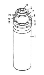
The device includes a container 1 containing a refrig-
erant. The refrigerant can be selected depending on the
particular application of the device and the required tempera-
tures. In this case it is an aerosol containing butane/propane,
but can also be liquefied CO2 or any other useful refrigerant.
Refrigerant is to mean any liquid or gas which is able to ex-
tract heat due to evaporation and/or expansion or other cooling
processes. So, for example, also propellants that have a cooling
effect is considered to be a refrigerant. The container may be a
standard spray or aerosol can having a valve (not shown) and an
outlet tube 2 (see Figs. 9 - 12). The can may have a capacity of
25 - 250 ml, more particular 50 - 100 ml, for example. The con-
CA 02936148 2016-07-07
WO 2014/114696 6 PCT/EP2014/051293
tamer 1 is more or less cylindrical having a collar 3 spaced
around the outlet tube 2.
An applicator 4 is mounted on container 1 at the end
containing outlet tube 2. For this mounting purpose, applicator
4 comprises a sleeve portion 5 adapted to engage around the
outer surface of container 1.
In the embodiments of Fig. 1 and 2, sleeve portion 5 is
relatively long and engages around a considerable length of con-
tainer 1, at least up to the cylindrical main portion of the
container. In this embodiment, applicator 4 is removable from
container 1. The sleeve portion 5 is just engaging around con-
tainer 1 with a sliding (frictional) fit and without any stop
preventing removal of applicator 4.
In the embodiment of Figs. 3 and 4, sleeve portion 5 is
shorter, but comprises an inner ridge 6 or the like at the open
end of sleeve portion 5 engaging behind collar 3 of container 1,
thus functioning as a stop preventing removal of applicator 4
and determining the non-actuating position of the applicator on
the outlet tube 2 and valve.
In both embodiments, the valve of container 1 is actu-
ated by depressing outlet tube 2 by means of applicator 4 which
must thus also be depressed. During this sliding movement, the
applicator is guided by sleeve portion 2 engaging around con-
tainer 1 and by outlet tube 2.
The sleeve portion 5 of applicator 4 is part of an
outer wall thereof and connects to a dome-shaped wall portion 7.
These wall portions 5, 7 together with the top of container 1
define a chamber 8 within applicator 4. The sleeve portion 5 may
be sealed to container 1 in such a way that it prevents leakage
of liquid refrigerant from chamber 8, but allows the passage of
gaseous refrigerant.
Mounted within chamber 8 is a heat exchanger comprising
a porous member 9, for example made from a material having good
heat conducting properties. One example thereof is sintered
metal such as brass having pores allowing passage of refriger-
ant. The porous member 9 is positioned around the outlet opening
of outlet tube 2 of container 1. The porous member 9 has a cav-
ity 10 (see Figs. 9 - 12) where the refrigerant from outlet tube
2 enters and where it will expand thereby absorbing energy from
CA 02936148 2016-07-07
WO 2014/114696 PCT/EP2014/051293
7
the cavity and surrounding porous member 9 thus effecting a
cooling thereof. On the end of porous member 9 remote from out-
let tube 2 and adjacent the wall portion of applicator 4, there
is provided a contact member 11 to contact the site to be
treated. This contact member and/or the heat exchanger is closed
such that refrigerant cannot escape from the heat exchanger or
chamber 8 through this contact member 11. This contact member 11
can be a separate part attached to porous member 9, but it may
also be integrated in the porous member, while it is made imper-
meable, for example by melting, impregnating or adding a
separate part or layer of metal or plastic to porous member 9.
The contact member 11 is mainly cylindrical and slightly pro-
trudes through an opening in the top of the dome-shaped wall
portion 7 of applicator 4, which is flattened in the embodiment
shown, so that wall portion 7 is substantially in the form of a
truncated cone, having in its centre the circular outer surface
of contact member 11. However, contact member 11 may be covered
by a thin protective layer of for example plastic in some em-
bodiments. The contact member does not have to protrude
completely through the outer wall of applicator 4. It just needs
to be exposed to such an extent that it can cool the site to be
treated to a desired extent, either directly, or indirectly
through an additional member.
The porous member 9 is mounted within applicator 4 by
means of a mounting member 12. This mounting member 12 is here
formed as a separate plastic part. It has a bottom portion 13
including in its centre a cavity 14 in which outlet tube 2 fits.
Cavity 14 communicates with a passage 15 through bottom portion
13 to allow refrigerant to enter cavity 10 within porous member
9 through bottom portion 13 of mounting member 12.
In the embodiments of Figs. 1 and 3, bottom portion 13
extends up to the outer wall of applicator 4, in particular
sleeve portion 5 thereof. This is provided with a circumferen-
tial inner groove 16 in which the circumferential edge of bottom
portion 13 can snap to attach the mounting member 12 to the
outer wall of applicator 4 and thereby also mounting porous mem-
ber 9 and contact member 11. In fact, when mounting member 12 is
seated with its edge in groove 16 it presses porous member 9
against the outer wall of applicator 4 surrounding the opening
CA 02936148 2016-07-07
WO 2014/114696 8 PCT/EP2014/051293
for contact member 11. This pressing contact enables a gas tight
seal (with or without any assistance of a sealant) between the
upper surface of porous member 9 and the inner surface of outer
wall portion 7 of applicator 4 thus preventing escape of refrig-
erant there, also with varying temperatures of porous member 9
due to the refrigerant.
The mounting member 12 in the embodiments of Figs. 1
and 3 includes an upright wall member 17 forming together with
bottom portion 13 a receptacle for any liquid refrigerant escap-
ing from porous member 9. The wall member ends at a distance
from the outer wall of applicator 4, so that receptacle is open
to chamber 8 of the applicator. The wall member 17 closely sur-
rounds the outer surface of porous member 9 thus only leaving a
narrow annular space between them thereby forcing any liquid re-
frigerant to stay in contact with the outer surface of porous
member 9 and thus withdrawing heat from porous member 9. This
improves the efficiency of the heat exchanger.
When during normal use of the device the valve of the
container is actuated with the device in an upright position,
all liquid refrigerant will be received in the receptacle and
will be evaporated before the applicator is moved to an upside
down position in which contact member 11 is exposed to the site
to be treated. The bottom portion 13 outside upright wall member
17 will normally be open to allow gaseous refrigerant to escape.
In the embodiments of Figs. 2 and 4, mounting member 12
is formed differently. Bottom portion 13 is now terminated short
of sleeve portion 5, but upright wall member 17 is extended up
to inner surface of dome shaped wall portion 7 and the upper end
of wall member 17 is provided with a collar 18 adapted to snap
into a groove 19 in the inner surface of outer wall portion 7.
In order to vent the receptacle to chamber 8 of the applicator,
one or more recesses 20 or openings are provided in collar 18
(see Figs. 2 and 4) so that gaseous refrigerant can escape from
the receptacle to chamber 8 and then to the environment.
Not shown in the drawings is a cover that fits onto the
applicator to cover the contact member. The cover or the appli-
cator may be provided with a child lock, for example such that
the cover and applicator can only be depressed after a small ro-
tation of the cover and/or applicator. This can be effected by
CA 02936148 2016-07-07
WO 2014/114696 9 PCT/EP2014/051293
providing a member allowing depression of the applicator in one
rotational position and preventing depression in another rota-
tional position.
Use of the devices as shown is as follows. In the
unlocked position, applicator 4 is depressed with respect to
container 1 against spring pressure of the valve, preferably
with the cover on the applicator. Depressing is continued until
a sufficient amount of refrigerant from container 1 has entered
cavity 10 within porous member 9 of the heat exchanger. There
the liquid refrigerant will evaporate and withdraw heat from the
porous member so that the temperature thereof will drop. The
pores of the porous member 9 will enable a good and wide spread
contact between the refrigerant and the material of porous mem-
ber 9. Due to the good heat conducting properties, also the
temperature of contact member 11 will drop to the same degree,
depending on the type of and amount of refrigerant supplied to
the heat exchanger. Any liquid refrigerant that passes through
the porous member will be received in the receptacle formed by
bottom portion 13 and upright wall member 17 and thus is kept in
close contact with the heat exchanger. If the pressure in cham-
ber 8 is rising above that of the environment, gaseous
refrigerant may escape between the sleeve portion 5 and outer
surface of container 1. Due to the pressure between the upper
surface of porous member 9 and the lower surface of outer wall
portion 7 exerted by mounting member 12 and by the user depress-
ing the applicator, no gaseous refrigerant will escape at the
position of contact member 11.
After a prescribed time, the temperature of contact
member 11 will be at the required level and the user may stop
depressing applicator 4 so that it will return to its rest posi-
tion by the spring force of the valve of container 1. The user
may remove the cover, if he/she has not already done so. The
contact member 11 may then be brought into contact with the site
to be treated, for example with the wart. The wart will be fro-
zen by the contact member and due to the limited surface that is
at such lowered temperature, there is no risk of surroundings of
the wart being frozen, so that there is hardly any risk of skin
burns. In this application, the upper surface of the contact
02936148 2016-07-07
WO 2014/114696 10 PCT/EP2014/051293
member may for example be between 3 and 5 mm, in particular sub-
stantially 4 mm.
In the embodiment of Figs. 1 and 2, the applicator may
or may not be removed from the container before it is applied to
the site to be treated.
Figs. 13 - 16 show a further embodiment of the applica-
tor, which is provided with a child-proof lock to prevent the
applicator from becoming activated, in this case depressed, by a
child. In this embodiment, the housing of the applicator is made
in two parts: sleeve portion 5 is mounted on container 1 and
dome-shaped outer wall portion 7 is mounted to sleeve portion 5,
such that wall portion 7 is axially fixed but may rotate to a
limited extent with respect to portion 5, around an axis which
is in line with the axis of container 1. The sleeve portion 5
shows in opposite positions two markings: an 0 indicating the
rotational position of dome-shaped portion 7 in which the acti-
vation is disabled (a marking = on dome-shaped wall portion 7 is
then aligned with the 0), and an I with which the marking = must
be aligned in order to be able to activate the applicator by
jointly depressing dome-shaped wall portion 7 and sleeve portion
5. The two markings may be off-set e.g. 10 - 30 , such as ca.22 .
In this embodiment, dome-shaped wall portion 7 is bi-
ased towards its disabled position, so that a user must hold the
dome-shaped wall portion 7 in its rotated position when it is
depressed. When the user releases dome-shaped wall portion 7 it
will spring back to its locked position.
The child-proof lock in this embodiment comprises lock-
ing members in the form of locking cams 21. In the locking
position, these cams 21 are positioned in seats 22 near the cir-
cumference of wall portion 7. The cams 21 are then positioned
above upper collar 3 of container 1, thereby preventing a down-
ward movement of dome-shaped portion 7 and sleeve portion 5
because cams 21 are stopped by collar 3. Each seat 22 includes a
supporting surface 22A supporting the respective cam 21 in axial
direction. The cams 21 are mounted at free ends of transmitting
or holding members, here flexible arms 23 which are curved and
which are mounted on their ends remote from cams 21 to a part of
the applicator that is connected to sleeve portion 5, in this
case to radial ribs 24 extending between upright wall member 17
CA 02936148 2016-07-07
WO 2014/114696 PCT/EP2014/051293
11
and sleeve portion 5. The arms 23 extend mainly in circumferen-
tial direction and connect to cams 21 more in radial direction.
The seats 22 have a seat wall portion 25 mainly in ra-
dial direction on the side of arms 23. These seat wall portions
25 urge cams 21 radially inwardly when the seats 22 are moved
mainly in circumferential direction upon rotation of dome-shaped
wall portion 7 and the arms 23 are held by ribs 24 thereby pull-
ing cams 21 away from their seats 24 to move along the seat wall
portions 25. This inward, more or less radial movement of cams
21 causes cams 21 to move out of engagement with collar 3, such
that there is no part below cams 21 blocking their movement. The
cams and therewith dome-shaped wall portion 7 and sleeve portion
5 may then be depressed with respect to container 1. As a re-
sult, outlet tube 2 of container 1 may be depressed by a member
of applicator 4, in this case bottom portion 13 of mounting mem-
ber 12, and thus the valve of the container is opened to allow
coolant to enter applicator 4. When dome-shaped wall portion 7
is released, it will spring back upwardly by the spring pressure
of outlet tube 2, while the spring pressure in arms 23 will ro-
tate dome-shaped wall portion 7 back to the locked position with
the cams aligned with collar 3 of the container 1.
In an alternative embodiment not shown, the spring
force of the arms may be reduced such that dome-shaped wall por-
tion 7 will not be biased to the locked position. The dome-
shaped wall portion 7 may then remain in the unlocked position
(aligned with I) and may be rotated back to the locked position
manually. In such embodiment, wall portion 7 and sleeve portion
5 may be provided with click members to mark the locked and
unlocked position. It is conceivable to connect the holding and
locking members to the dome-shaped outer wall portion 7 and to
form the seats to the sleeve portion 5, as long as there is a
relative movement between the locking members and a part moving
the locking member(s) away from the collar of the container. The
movement of the locking member(s) away from the collar could
also be outwardly, or axially away from the collar. If the
sleeve portion 5 would be axially stationary with respect to the
container, and wall portion 7 would be axially movable with re-
spect to the sleeve portion, then the locking members could also
CA 02936148 2016-07-07
WO 2014/114696 PCT/EP2014/051293
12
cooperate indirectly with the collar through a part of sleeve
portion 5.
The child-proof lock can be used with other devices as
well, where an aerosol can is activated to release a substance
by depression of an applicator (which may also be a spraying de-
vice or the like).
From the foregoing it will be clear that the invention
provides a device which is very easy to handle and operate with-
out the risk of skin burns. The device can be easily controlled
either by design and/or operation. For example, temperature can
be controlled either by the choice of material for the heat ex-
changer/contact member or by regulating the amount of
refrigerant supplied. This can be done either manually or auto-
matically by for example a time switch or bimetal switch in the
supply.
The invention is not limited to the embodiments shown
in the drawings and described above which can be varied in dif-
ferent manners within the scope of the invention. First of all,
it is noted that features of different embodiments can be used
in other combinations. Furthermore, it is possible to replace
parts of the device by alternative arrangements. For example, in
stead of a sintered porous member, it is possible to use a mem-
ber having one or more channels or passages formed therein
allowing close contact between refrigerant and heat exchanger.
The receptacle to keep escaping liquid refrigerant in close con-
tact with the heat exchanger can be combined with different
types of heat exchangers. The mounting member and the wall por-
tions of the applicator are generally made of plastic material.
Especially the outer wall of the applicator is preferably made
of material having a low heat conductivity (much lower than that
of the porous member and contact member, so that the temperature
of the applicator does not lower too much). At least part of the
mounting member or receptacle may also be made in one piece with
the heat exchanger. In other applications, especially those with
moderately reduced temperatures, such as for treating swellings,
the outer surface of the contact member will be much larger to
contact a larger surface of the skin. Thus, the shape of the
outer surface of the contact member will be varied in accordance
with the disorder to be treated. In case of an applicator for
CA 02936148 2016-07-07
WO 2014/114696 13 PCT/EP2014/051293
treating piles in the anus, the applicator will have a narrower
elongated part containing the contact member so that it can be
inserted in the anus and the contact member surface will (also)
be on the circumference of the elongated part, not (only) at the
end thereof. The contact member surface may be covered by a thin
layer of plastic. In other applications, especially for cosmetic
purposes or for treating bites, the contact member surface may
be covered by a soft layer, for example from plastic, resin or
gel. Temperature control may be effected by changing the thick-
ness of the layer. Such applicator may be used in combination
with a skin moisturizer, ointment or the like.
Figs. 21 - 24 show such embodiment where applicator 4
can be used in combination with an ingredient, in particular ac-
tive ingredient. In the embodiment shown, the active ingredient
is accommodated in a porous member 26, such as foam disposable,
that can be removably attached, for example clicked or screwed,
to applicator 4. In the embodiment shown, applicator 4 is re-
cessed in the surroundings of contact member 11 in order to
accommodate porous member 26 in contact with contact member 11.
Thus, here contact member 11 is exposed to the outside through
porous member 26, and thus indirectly to the site to be treated.
The porous member may be deformable to release the active ingre-
dient by pressure, but also other ways of releasing the
ingredient are conceivable. The material and shape of the porous
member is generally soft and/or smooth, such that it feels
pleasant to the skin. The ingredient will generally be fluid, in
particular cream or paste like, and may be active or may be in-
active, just to feel pleasant to the skin during massage or
cooling of the skin. The porous member 26, i.e. the foam dispos-
able contains sufficient ingredient for one or a few treatments.
The applicator 4 cools porous member 26, for example to a tem-
perature between 5 and 10 'C, and the porous member is configured
to cool and massage the skin while releasing the active ingredi-
ent, as is illustrated in Fig. 23. Of course it is also possible
to release the active ingredient first and then massage and cool
the skin with the released ingredient. This method may be used,
for example, for treating burns and stings, eye wrinkles, tired
eyes, eczema or other skin irritation, nail and/or foot fungus,
headache, swollen lips, sunburn in the face, is may be used on
CA 02936148 2016-07-07
WO 2014/114696 14 PCT/EP2014/051293
the feet by foot massage, it may be used during pregnancy and
the like.
Fig. 24 shows porous member 4 packed in a package 27,
such as a plastic foil or another packaging, so that the active
ingredient is protected from the environment before use.
It is also conceivable to provide a porous member that
is not attached to the applicator, but can be brought into con-
tact with contact member 11 of applicator 4 in order to be
cooled. The porous member may then be released an used sepa-
rately.
This combination of cooling and application of active
ingredients also enables the development and use of active in-
gredients that have improved functionality and/or are more
active at lower temperatures Generally, the applicator and the
container will be a disposable unit. However, especially with
the embodiment in which the applicator is removable from the
container, it is possible to have a reusable applicator sold
separately, so that if the container is empty it can be replaced
by a new one to which the old applicator is mounted. Therefore
the invention also covers an applicator without the container,
which is adapted to be mounted to a fitting container. The valve
for supplying refrigerant may also be present in the applicator.