Note: Descriptions are shown in the official language in which they were submitted.
CA 02936313 2016-07-08
1
SP356989W000
DESCRIPTION
TRANSMISSION DEVICE, TRANSMISSION METHOD, RECEPTION DEVICE,
AND RECEPTION METHOD
TECHNICAL FIELD
[0001]
The present invention relates to a transmission device,
a transmission method, a reception device, and a reception
method, and specifically relates, for example, to a
transmission device that transmits video data after
compressing the range of levels of the video data.
BACKGROUND ART
[0002]
1!) It is known that displaying a High Dynamic Range (HDR)
image in a wide dynamic range on a Low Dynamic Range (LDR)
monitor configured to display an image with normal brightness
generates the clipped blacks in the dark parts and the clipped
whites in the blight part of the HDR image and makes the image
wholly dark. Fig. 23(a) illustrates exemplary distribution
of luminance levels of an original HDR image in a range of
levels between zero and 100*N%. In this example, the values
of "%" are the percentages of brightness when 100 cd/m2 is
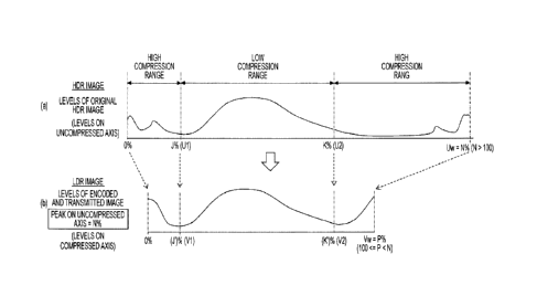
100%. Fig. 23(b) illustrates exemplary distribution of
luminance levels of the LDR image provided by compressing the
original HDR image to the LDR range. The peak luminance of
the LDR image is at a lower level than the level of the peak
luminance of the HDR image. This makes the LDR image wholly
dark.
[0003]
Gamma correction is also known . In the gamma correction,
CA 02936313 2016-07-08
2
SP356989W000
inputting data with the characteristic opposite to the
characteristic of the monitor corrects the gamma
characteristic of the monitor. For example, Non-Patent
Document 1 describes that applying a gamma curve to input video
data at levels of 0 to 100%*N (Nis larger than one) provides
video data for transmission, and encoding the video data for
transmission generates a video stream . Then, the video stream
is transmitted.
CITATION LIST
NON-PATENT DOCUMENT
[0004]
Non-Patent Document 1: High Efficiency Video Coding (HEVC)
text specification draft 10 (for FDIS & Last Call)
SUMMARY OF THE INVENTION
PROBLEMS TO BE SOLVED BY THE INVENTION
[0005]
An objective of the present invention is to allow for
good display of an LDR image generated from HDR video data.
SOLUTIONS TO PROBLEMS
[0006]
A concept of the present invention lies in a transmission
device including:
a level conversion unit that provides video data for
transmission in a second range of levels narrower than or equal
to a first range of levels by applying a predetermined
level-mapping curve to input video data in the first range
of levels; and
a transmission unit that transmits the video data for
CA 02936313 2016-07-08
3
SP356989W000
transmission together with auxiliary information used to
convert the levels on a receiving end.
[0007]
According to the present invention, the level conversion
unit provides the video data for transmission in a second range
of levels narrower than or equal to a first range of levels
by applying a predetermined level-mapping curve to the input
video data in the first range of levels. For example, the
first range of levels may be between zero and N%, the N being
1C a number larger than 100, and the second range of levels may
be between zero and P%, the P being a number larger than or
equal to 100 and smaller than or equal to the N.
[0008]
The transmission unit transmits the video data for
transmission provided by the level conversion unit together
with the auxiliary information used to convert the levels on
the receiving end. For example, the transmission unit may
transmit a video stream provided by encoding the video data
for transmission, and the auxiliary information maybe inserted
2C in a layer of the video stream.
[0009]
According to the present invention as described above,
for example, applying a predetermined level-mapping curve to
the input video data in the first range of levels provides
the video data for transmission in the second range of levels
narrower than the first range of levels. Then, the video data
for transmission is transmitted to the reception device . Thus,
using an appropriate characteristic to the contents of the
image as the predetermined level-mapping curve allows for good
display of an LDR image generated from the video data for
transmission. Furthermore, according to the present
CA 02936313 2016-07-08
4
SP356989W000
invention, the auxiliary information used to convert the levels
on the receiving end is transmitted together with the video
data for transmission. This enables, for example, the
receiving end to appropriately convert the levels of the video
data for transmission in accordance with the auxiliary
information, and thus to display an image in good condition.
[0010]
Note that, in the present invention, for example, the
auxiliary information may be the level-mapping curve
information and/or the electro-optical conversion
characteristic information. In this example, the receiving
end can reproduce an HDR video data for an HDR monitor from
the video data for transmission in accordance with the
level-mapping curve information, and thus can display an HDR
image in good condition.
[0011]
Furthermore, the receiving end, for example, can convert
the levels of the video data for transmission or the levels
of the video data provided by mapping the levels of the video
data for transmission in the level mapping in accordance with
the level-mapping curve information into the levels suitable
for the gamma characteristic of the monitor in accordance with
the electro-optical conversion characteristic information
(in electro-optical conversion). Thus, an image can be
displayed in good condition.
[0012]
For example, the electro-optical conversion
characteristic information that the transmission unit
transmits together with the video data for transmission may
include information of a plurality of electro-optical
conversion characteristics. In this example, for example,
CA 02936313 2016-07-08
S2356989W000
the receiving end can automatically or manually select an
electro-optical conversion characteristic suitable for the
brightness of the environment in which the image is viewed
among a plurality of electro-optical conversion
5 characteristics and use the selected electro-optical
conversion characteristic. This enables the receiving end
to display a high-quality image suitable for the brightness
of the environment in which the image is viewed.
[0013]
Furthermore, another concept of the present invention
lies in a reception device including:
a reception unit that receives video data for
transmission in a second range of levels narrower than or equal
to a first range of levels, the video data for transmission
1!, being providedby applying a predetermined level-mapping curve
to input video data in the first range of levels; and
a processing unit that converts the levels of the video
data for transmission in accordance with auxiliary information
received together with the video data for transmission.
[0014]
According to the present invention, applying a
predetermined level-mapping curve to the input video data in
the first range of levels provides the video data for
transmission in the second range of levels narrower than or
equal to the first range of levels. Then, the reception unit
receives the video data for transmission in the second range
of levels. The processing unit converts the levels of the
video data for transmission in accordance with the auxiliary
information received together with the video data for
transmission.
[0015]
CA 02936313 2016-07-08
6
SP35698916000
As described above in the present invention, the levels
of the video data for transmission is converted in accordance
with the auxiliary information received together with the video
data for transmission. Thus, the levels of the video data
for transmission are appropriately converted. This
appropriate conversion allows for display of an image on a
monitor in good condition.
[0016]
Note that, in the present invention, for example, the
auxiliary information may be level-mapping curve information
and/or electro-optical conversion characteristic information.
In this example, for example, the HDR video data for an HDR
monitor can be reproduced from the video data for transmission
in accordance with the level-mapping curve information. Thus,
1!) an HDR image can be displayed in good condition. Furthermore,
in this example, for example, the levels of the video data
for transmission or the levels of the video data provided by
mapping the levels of the video data for transmission in
accordance with the level-mapping curve information in level
2(1 mapping can be converted into the levels suitable for the gamma
characteristic of the monitor in accordance with the
electro-optical conversion characteristic information (in
the electro-optical conversion) . Thus, an image can be
displayed in good condition.
25 [0017]
For example, the processing unit may provide the video
data for output in a third range of levels wider than the second
range of levels by mapping the levels of the video data for
transmission in the second range of levels in accordance with
30 the level-mapping curve information. In such a case, for
example, the first range of levels may be between zero and
CA 02936313 2016-07-08
7
SP356989W000
N%, the N being a number larger than 100, the second range
of levels may be between zero and P%, the P being a number
larger than or equal to 100 and smaller than or equal to the
N, and the third range of levels may be between zero and Q%,
the Q being a number larger than or equal to 100 and smaller
than or equal to the N. In such a case, a highest level in
the third range of levels maybe determined in accordance with
information about a highest level able to be displayed.
[0018]
Furthermore, for example, the processing unit may
provide video data for output by electro-optically converting
the video data for transmission in the second range of levels
or video data in a third range of levels wider than or equal
to the second range of levels in accordance with the
electro-optical conversion characteristic information in
electro-optical conversion, and the video data in the third
range of levels is provided by converting the levels of the
video data for transmission in accordance with the
level-mapping curve information.
[0019]
Furthermore, for example, the electro-optical
conversion characteristic information received together with
the video data for transmission may include information of
the electro-optical conversion characteristics, and a
selection unit that selects an electro-optical conversion
characteristic used in the processing unit among a plurality
of electro-optical conversion characteristics. In such a
case, for example, the selection unit may select an
electro-optical conversion characteristic used in the
processing unit among the electro-optical conversion
characteristics in accordance with an output from a sensor
CA 02936313 2016-07-08
8
SP356989W000
or an input by user operation. In this example, the
electro-optical conversion characteristic suitable for the
brightness of the environments in which the image is viewed
can automatically or manually be selected among the
electro-optical conversion characteristics and used. Thus,
an image suitable for the brightness of the environments in
which the image is viewed can be displayed in good condition.
EFFECTS OF THE INVENTION
[0020]
The present invention allows for good display of an LDR
image generated from HDR video data. Note that the effects
described herein are merely examples, and the effects of the
present invention are not limited to the described effects.
The effects of the present invention may include an additional
effect.
BRIEF DESCRIPTION OF DRAWINGS
[0021]
2( Fig. 1 is a block diagram of an exemplary configuration
of a transmission and reception system as an embodiment.
Figs. 2(a) and 2(b) are explanatory diagrams of HDR
conversion performed on a transmitting end.
Fig. 3 is a diagram of exemplary HDR conversion
characteristics (level-mapping curves).
Figs. 4(a) to 4(c) are explanatory diagrams of HDR
reverse conversion performed on the receiving end.
Fig. 5 is a diagram of exemplary HDR reverse conversion
characteristics (level-mapping curves).
Fig. 6 is a diagram of exemplary electro-optical
conversion characteristics.
CA 02936313 2016-07-08
9
SP356989W000
Fig. 7 is a block diagram of an exemplary configuration
of a transmission device.
Fig. 8 is a diagram of the access unit at the beginning
of a GOP when the coding scheme is HEVC.
Fig. 9 is a diagram of an exemplary structure of an HDR
mapping SET message.
Fig. 10 is a diagram of an exemplary structure of an
HDR mapping SET message.
Fig. 11 is a diagram of the contents of the main
information in the exemplary structure of the HDR mapping SEI
message.
Fig. 12 is a diagram of an exemplary structure of an
HDR information descriptor.
Fig. 13 is a diagram of the contents of the main
information in the exemplary structure of the HDR information
descriptor.
Fig. 14 is a diagram of an exemplary structure of a
transport stream.
Fig. 15 is a block diagram of an exemplary configuration
of a reception device.
Fig. 16 is a diagram of exemplary combinations of a main
type indicated in the information "eotf_table_type_main" and
a sub type indicated in the information "eotf_table_type_sub" .
Fig. 17 is an explanatory diagram of the characteristics
of conversion curves indicated by the main and sub types.
Fig. 18 is a schematic diagram of the cooperation of
HDR reverse conversion and electro-optical conversion in the
reception device.
Fig. 19 is a flowchart of an exemplary flow of the process
performed with the reception device.
Figs. 20(a) and 20(b) are explanatory diagrams of the
CA 02936313 2016-07-08
SP356989W000
electro-optical conversion characteristic on which the HDR
reverse conversion characteristic is reflected.
Figs. 21(a) and 21(b) are explanatory diagrams of the
electro-optical conversion characteristic on which the HDR
5 reverse conversion characteristic is reflected.
Figs. 22(a) and 22(b) are explanatory diagrams of the
opto-electronic conversion characteristic on which the HDR
conversion characteristic is reflected.
Figs. 23(a) and 23(b) are diagrams illustrating that,
1(1 when an LDR image is provided by the compression of an HDR
image to an LDR range, the peak luminance of the LDR image
is at a lower level than the level of the peak luminance of
the HDR image.
MODE FOR CARRYING OUT THE INVENTION
[0022]
The mode for carrying out the invention (hereinafter
referred to as an "embodiment") will be described hereinafter .
Note that the embodiment will be described in the following
order.
1. Embodiment
2. Exemplary variation
[0023]
<1. Embodiment>
[Exemplary Configuration of Transmission and Reception
System]
Fig. 1 illustrates an exemplary configuration of a
transmission and reception system 10 as the embodiment. The
transmission and reception system 10 includes a transmission
device 100 and a reception device 200.
[0024]
CA 02936313 2016-07-08
11
SP356989W000
The transmission device 100 generates an MPEG-2
transport stream TS as a container, and transmits the MPEG-2
transport stream TS on a broadcast wave or in packets on the
Internet. The transport stream TS includes a video stream
provided by encoding video data for transmission.
[0025]
The video data for transmission is the video data of
anLDRimageprovidedbyapplyingapredeterminedlevel-mapping
curve to the video data of an original HDR image that is the
input video data. In the application, the range of levels
of the video data for transmission is compressed from the range
of levels of the input video data. However, the whole range
of levels is not necessarily compressed evenly. Depending
on the level-mapping curve, a low-compression range and a
high-compression range are generated. The width or position
of the low-compression range also varies.
[0026]
In the example, the original HDR image, namely, the input
video data is in a first range of levels, and the image to
2C be transmitted, namely, the video data for transmission is
in a second range of levels narrower than the first range of
levels. Fig. 2(a) illustrates the levels of the original HDR
image, in other words, illustrates exemplary distribution of
levels of the input video data. In the example, the input
video data is in a range of levels between zero and N% (N >
100). Fig. 2(b) illustrates the levels of the encoded and
transmitted image, in other words, illustrates exemplary
distribution of levels of the video data for transmission.
In the example, the video data for transmission is in a range
of levels between zero to P% (100 < = P < N). Note that the
values of "%" indicate a value relative to 100 cd/m2 that is
CA 02936313 2016-07-08
12
SP356989W000
100%.
[0027]
The range from zero to J% of the input video data is
a high-compression range. The range is converted into a range
from zero to J'% of the video data for transmission with a
level mapping process. The range from J to K% of the input
video data is a low-compression range. The range is converted
into a range from J' to K'% of the video data for transmission
with the level mapping process. The range from K to N% of
the input video data is a high-compression range. The range
is converted into a range from K' to P% of the video data for
transmission with the level mapping process.
[0028]
In the example, the low-compression range is a range
of levels of lightness in which the original image is
transmitted with minor quality loss due to the level mapping
process. On the other hand, the high-compression range is
a range of levels in which the levels of the original image
are proactively compressed to predetermined levels for display
in the level mapping process. Selectively compressing the
range of levels as described above allows for appropriate
display of the darkness and brightness of the image on a display
device (monitor) that is not compatible with an HDR image.
[0029]
Fig. 3 illustrates exemplary HDR conversion
characteristics, namely, exemplary level-mapping curves. A
level-mapping curve (1) is an example in which the dark part
of an image is finely expressed. In this example, the range
of levels is divided into three ranges: a dark level range,
a middle level range, and a bright level range. The dark level
range is converted into a range with the largest number of
CA 02936313 2016-07-08
13
SP356989W000
levels, the middle level range is converted into a range with
the second largest number of levels, and the bright level range
is converted into a range with a small number of levels. A
level-mapping curve (2) is an example in which the part in
the middle level range of the image is finely expressed. In
this example, the middle level range of the three divided ranges
is converted into a range with the largest number of levels,
the bright level range is converted into a range with the second
largest number of levels, and the dark level range is converted
1( into a range with a small number of levels. A level-mapping
curve (3) is an example in which the parts in the three level
ranges of brightness of the image are evenly expressed. Fig.
3 illustrates the three linked level-mapping curves. Note
that, however, the number is not limited to three.
[0030]
The transmission device 100 transmits the video data
for transmission together with the auxiliary information used
to convert the levels of the video data on the receiving end.
For example, the transmission device 100 inserts the
2( level-mapping curve information and/or the electro-optical
conversion characteristic information as the auxiliary
information into a layer of the video stream.
[0031]
The level-mapping curve information includes, for
example, the percentage term of the peak level of brightness
on an uncompressed axis (see "Uw" in Fig. 3), the percentage
terms of levels of mapping points in the range to the percentage
term of the peak level on the uncompressed axis (see "Ul and
U2" in Fig. 3), the percentage term of the peak level of
brightness on a level-compressed axis (see "Vw" in Fig. 3),
and the percentage terms of levels of mapping points in the
CA 02936313 2016-07-08
14
SP356989W000
range to the percentage term of the peak level on the
level-compressed axis (see "V1 and V2" in Fig. 3). The
electro-optical conversion characteristic information
includes, for example, the type of the electro-optical
conversion characteristic, or the value of a lookup table (LUT)
indicating the electro-optical conversion characteristic.
[0032]
The reception device 200 receives the transport stream
TS transmitted from the transmission device 100 on a broadcast
wave or in packets on the Internet. The transport stream TS
includes the video stream provided by encoding the video data
for transmission . The reception device 200 provides the video
data for display (video data for output), for example, by a
process for decoding the video stream.
[0033]
As described above, the level-mapping curve information
and/or the electro-optical conversion characteristic
information are inserted as the auxiliary information in the
layer of the video stream. The reception device 200 generates
2( the video data of the HDR image to be replayed by reversely
converting the video data for transmission in HDR reverse
conversion that is opposite to the HDR conversion by the
transmission device 100 in accordance with the level-mapping
curve information.
[0034]
The range of levels of the video data of the HDR image
to be replayed is a third range of levels wider than or equal
to the second range of levels that is the range of levels of
the video data for transmission. The highest level (peak
level) of the video data of the HDR image to be replayed is
limited, for example, to the highest level (peak level) of
CA 02936313 2016-07-08
SP356989W000
the video data of the original HDR image or the highest level
(peak level) that the receiving function defines as the highest
level to display.
[0035]
5 Similarly to
Fig. 2 (b) , Fig. 4(a) illustrates exemplary
levels of the encoded and transmitted image, namely, exemplary
level distribution of the video data for transmission. In
this example, the video data for transmission is in a range
of levels between zero and P% (100 < = P < N) . Fig. 4(b)
10 illustrates
exemplary distribution of levels of the video data
of the HDR image provided by reversely converting the video
data for transmission in conversion opposite to the HDR
conversion on the transmitting end in accordance with the
level-mapping curve information. Similarly to the video data
15 of the original
HDR image, the video data of the HDR image
in this example is in a range of levels between zero and N%
(N > 100) .
[0036]
Fig. 5 illustrates exemplary HDR reverse conversion
2( characteristics
in accordance with the level-mapping curve
information. The HDR reverse conversion characteristics (1) ,
(2) , and (3) correspond to the level-mapping curves (1) , (2) ,
and (3) in Fig. 3, respectively.
[0037]
21 In the present
embodiment, the highest level of the video
data of the HDR image to be replayed, provided by the HDR reverse
conversion, is determined as described below depending on the
magnitude relationship between the highest level of the video
data of the original HDR image (N%) and the highest level that
30 the receiving
function defines as the highest level to display
(Q%) . In other words, when P < Q < N holds, the highest level
CA 02936313 2016-07-08
16
SP356989W000
of the video data of the HDR image to be replayed is Q%. When
P < N < Q holds, the highest level of the video data of the
HDR image to be replayed is N%.
[0038]
Fig. 4(b) illustrates the distribution of levels of the
video data of the HDR image to be replayed when the highest
level of the video data of the HDR image to be replayed is
N%. In this example, the range of levels of the video data
for transmission from zero to J'% is converted into the range
of levels of the HDR image to be replayed from zero to J% in
the HDR reverse conversion. The range of levels of the video
data for transmission from J' to K'% is converted into the
range of the video data of the HDR image to be replayed from
J to K% in the HDR reverse conversion.
1E, [0039]
The range of levels of the video data for transmission
from K' to P% is converted into the range of levels of the
video data of the HDR image to be replayed from K to N% in
the HDR reverse conversion. In this example, in order to
display a part at a high level value in the HDR image to be
replayed, the high level value of the part in the video data
of the HDR image to be replayed is provided by multiplying
the high level value of the part in the video data for
transmission by the ratio (N - K)/(P - K').
[0040]
Fig. 4(c) illustrates the distribution of levels of the
video data of the HDR image to be replayed when the highest
level of the video data of the HDR image to be replayed is
Q%. In this example, the range of levels of the video data
for transmission from zero to J'% is converted into the range
of levels of the video data of the HDR image to be replayed
CA 02936313 2016-07-08
17
SP356989W000
from zero to J% in the HDR reverse conversion. The range of
levels of the input video data from J' to K'% is converted
into the range of levels of the video data of the HDR image
to be replayed from J to K% in the HDR reverse conversion.
[0041]
The range of levels of the input video data from K' to
P% is converted into the range of levels of the video data
of the HDR image to be replayed from K to Q% in the HDR reverse
conversion. In this example, in order to display a part at
a high level value in the HDR image to be replayed, the high
level value of the part in the video data of the HDR image
to be replayed is provided by multiplying the high level value
of the part in the video data for transmission by the ratio
(Q - K)/(P - K').
[0042]
The reception device 200 generates the video data for
display (video data for output) by converting the video data
for transmission or the video data of the HDR image provided
by reversely converting the video data for transmission in
2( the HDR reverse conversion in accordance with the
electro-optical conversion characteristic information in an
electro-optical conversion process.
[0043]
Fig. 6 illustrates exemplary electro-optical
conversion characteristics. A curve a indicates an exemplary
electro-optical conversion characteristic used to display a
part at low luminance with a high degree of accuracy. A curve
b indicates an exemplary electro-optical conversion
characteristic used to roughly display a part at extremely
low luminance and display a part at another luminance with
a high degree of accuracy. A curve c indicates an exemplary
CA 02936313 2016-07-08
18
SP356989W000
electro-optical conversion characteristic used to display an
image while keeping a good balance between the part at high
luminance and the part at low luminance in the image. Note
that the opto-electronic conversion characteristic used in
the transmission device 100 is usually opposite to the
electro-optical conversion characteristic used in the
reception device 200.
[0044]
"Exemplary Configuration of Transmission Device"
1(1 Fig. 7 is
an exemplary configuration of the transmission
device 100. The transmission device 100 includes a control
unit 101, a camera 102, an opto-electronic conversion unit
103, an HDR conversion unit 104, a video encoder 105, a system
encoder 106, and a transmission unit 107. The control unit
101 includes a Central Processing Unit (CPU) , and controls
the operation of each unit in the transmission device 100 in
accordance with the control program stored in a storage unit
(not illustrated) .
[0045]
2( The camera
102 captures an image of an object and outputs
the video data as a High Dynamic Range (HDR) image. The video
data is in a range of levels from zero to 100%N, for example,
from zero to 400%, or zero to 800%. In this example, the level
of 100% corresponds to a value of white luminance of 100 cd/m2.
[0046]
The opto-electronic conversion unit 103
opto-electronically converts the video data provided from the
camera 102 by applying a gamma curve to the video data. The
HDR conversion unit 104 generates the video data for
transmission of an LDR image in a compressed range of levels
(see Figs. 2(a) and 2 (b) ) by converting the opto-electronically
CA 02936313 2016-07-08
19
SP356989W000
converted video data of the HDR image by applying a
predetermined level-mapping curve to the video data (see Fig.
3) in HDR conversion (level mapping). By this conversion,
for example, when an image input to the HDR conversion unit
104 is displayed with 12 bits or more, the image output from
the HDR conversion unit 104 is displayed with 10 bits or lower.
Note that, as the level-mapping curve used in this example,
a predetermined level-mapping curve linked to a parameter
indicating the brightness of the image is selected by an
automatic operation or the user operation.
[0047]
The video encoder 105 provides encoded video data by
encoding the video data for transmission generated with the
HDR conversion unit 104, for example, in MPEG-4 AVC, MPEG-2
video, or high Efficiency Video Coding (HEVC). The video
encoder 105 generates a video stream (video elementary stream)
including the encoded video data, using a stream formatter
provided on the downstream (not illustrated).
[0048]
Meanwhile, the video encoder 105 inserts the auxiliary
information into a layer of the video stream. The auxiliary
information is used to convert the levels on the receiving
end. The auxiliary information is the information about the
level-mapping curve used in the HDR conversion unit 104, and
the electro-optical conversion characteristic information.
The electro-optical conversion characteristic indicated in
the electro-optical conversion characteristic information
depends on the characteristics of the image and is selected
by automatic operation or the user operation.
[0049]
The system encoder 106 generates a transport stream TS
CA 02936313 2016-07-08
SP356989W000
including the video stream generated with the video encoder
105. The transmission unit 107 transmits the transport stream
TS on a broadcast wave or in packets on the Internet to the
reception device 200.
5 [0050]
Meanwhile, the system encoder 106 can insert the
identification information, which indicates that the
auxiliary information (the information about the
level-mapping curve and the electro-optical conversion
10 characteristic information) used to convert the levels on the
receiving end is inserted in the layer of the video stream,
into a layer of the transport stream TS. In such a case, the
system encoder 106 inserts the identification information,
for example, under a video elementary loop (Video ES loop)
15 of a Program Map Table (PMT) included in the transport stream
TS.
[0051]
The operation of the transmission device 100 illustrated
in Fig. 7 will briefly be described. The camera 102 captures
2( an image and provides the video data of the HDR image. Then,
the opto-electronic conversion unit 103 opto-electronically
converts the video data of the HDR image by applying the gamma
curve to the video data of the HDR image, and transmits the
opto-electronically converted video data to the HDR conversion
unit 104. The HDR conversion unit 104 generates the video
data for transmission of an LDR image by converting the
opto-electronically converted video data of the HDR image by
applying a predetermined level-mapping curve to the
opto-electronically converted video data of the HDR image in
HDR conversion (see Figs. 2(a) and (b) ) .
[0052]
CA 02936313 2016-07-08
21
SP356989W000
The video data for transmission of the LDR image
generated with the HDR conversion unit 104 is provided to the
video encoder 105. The video encoder 105 generates a video
stream (video elementary stream) including encoded video data
by encoding the video data for transmission of the LDR image,
for example, in HEVC . Meanwhile, the video encoder 105 inserts
the auxiliary information (the information about the
level-mapping curve and the electro-optical conversion
characteristic information) used to convert the levels on the
receiving end into a layer of the video stream.
[0053]
The video stream generated with the video encoder 105
is provided to the system encoder 106. The system encoder
106 generates an MPEG-2 transport stream TS including the video
stream. The transmission unit 107 transmits the transport
stream TS on a broadcast wave or in packets on the Internet
to the reception device 200.
[0054]
[Auxiliary Information, Identification Information,
and TS structure]
As described above, the auxiliary information (the
information about the level-mapping curve and the
electro-optical conversion characteristic information) is
inserted in the layer of the video stream. For example, when
HEVC is used as the encoding scheme, the auxiliary information
is inserted as an HDR mapping SET message (HDR_mapping SET
message) in the part of "SEIs" in the access unit (AU).
[0055]
Fig. 8 illustrates the access unit at the beginning of
a Group Of Pictures (GOP) when HEVC is used as the encoding
scheme. When HEVC is used as the encoding scheme, an SET
CA 02936313 2016-07-08
22
SP356989W000
message group "Prefix_SEIs" used for decoding is placed before
"slices" in which pixel data is encoded, and an SEI message
group "Suffix SEIs" used for display is placed after the
"slices". The HDR mapping SET message is placed as the SET
message group "Suffix SEIs".
[0056]
Fig. 9 and Fig. 10 illustrate an exemplary structure
(Syntax) of the "HDRmapping SEI message" . Fig. 11 illustrates
the contents of the main information in the exemplary structure
(Semantics) . The "HDR_mapping refresh flag" is the one-bit
flag information. The "1" indicates that the previous message
about HRD mapping is refreshed. The "0" indicates that the
previous message is not refreshed.
[0057]
When the "HDR mapping refresh flag" is "1", the
¨ ¨
following information exists. The eight-bit field of
"coded data _bits" indicates the bit length of encoded data
with values. The 16-bit field of
"uncompressed peak_level percentage" indicates the
percentage term of the highest level of the source image data
(the value relative to 100 cd/m2) , for example, the value of
"Uw" in Fig. 3. The 16-bit field of
"compressed peak_level_percentage" indicates the percentage
term of the highest level of the encoded image data (the value
relative to 100 cd/m2) , for example, the value of "Vw" in Fig.
3.
[0058]
The "level_mapping flag" is the one-bit flag
information indicating whether the parameters for level
mapping exist . The "1" indicates that the parameters for level
mapping exist. The "eotf_linked_flag" is the one-bit flag
CA 02936313 2016-07-08
23
SP356989W000
information indicating whether to use the conversion curve
of the electro-optical conversion (EOTF) in order to perform
the level mapping. The "1" indicates that the conversion curve
of the electro-optical conversion (EOTF) is used to perform
the level mapping.
[0059]
When the "level mapping flag" is "1", the following
information exists. The eight-bit field of
"number of mapping periods" indicates the number of linked
_ _ _
level-mapping curves. For example, the number of linked
level-mapping curves is three in Fig. 3. The 16-bit field
of "compressed mapping point" indicates a point where the
level-mapping curve varies on the level-compressed axis with
the percentage term on the assumption that the
"compressed peak_level_percentage" is 100%. For example,
the point is the value of "V1, V2, or Vw" in Fig. 3. The 16-bit
field of "uncompressed mapping point" indicates a point where
the level-mapping curve varies on the level-uncompressed axis
with the percentage term on the assumption that the
"uncompressed_peak_level_percentage" is 100%. For example,
the point is the value of "Ul, U2, or Uw" in Fig. 3.
[0060]
When the "eotf linked flag" is "1", the following
_ _
information exists. The four-bit field of
"eotf table type main" indicates the main type of the
conversion curve of the electro-optical conversion (EOTF) ,
and indicates that a conversion curve of the electro-optical
conversion (EOTF) specialized for a specific image is
transmitted when the "eotf linked flag" is "OxF". The 16-bit
_ _
field of "tbl [j ] " indicates the output value from the input
value "j" on the transmitted conversion curve of the
CA 02936313 2016-07-08
24
SP356989W000
electro-optical conversion (EOTF).
[0061]
Fig. 12 illustrates an exemplary structure (Syntax) of
an HDR information descriptor (HDR information descriptor)
as the identification information. Fig. 13 illustrates the
contents of the main information in the exemplary structure
(Semantics).
[0062]
The eight-bit field of "HDR information descriptor tag"
indicates the type of the descriptor, and indicates that the
type is the HDR information descriptor in this example. The
eight-bit field of "HDR_ information descriptor length"
indicates the length (size) of the descriptor, and indicates
the number of subsequent bytes as the length of the descriptor.
[0063]
The one-bit field of "HDR_mapping_SEI_existed" is the
flag information indicating whether the HDR mapping SEI
information exists in a video layer (a layer of the video stream) .
The "1" indicates that the HDR mapping SEI information exists
while the "0" indicates that the HDR mapping SEI information
does not exist.
[0064]
Fig. 14 illustrates an exemplary structure of the
transport stream TS. The transport stream TS includes a PES
packet "PID1 :video PES1" of the video elementary stream. The
HDR mapping SEI message (HDR_mapping SEI message) is inserted
in the video elementary stream.
[0065]
The transport stream TS further includes a Program Map
Table (PMT) as the Program Specific Information (PSI). The
PSI indicates which program each elementary stream included
CA 02936313 2016-07-08
SP356989W000
in the transport stream belongs to. The transport stream TS
further includes an Event Information Table (EIT) as the
Serviced Information (SI) used to manage each event (program) .
[0066]
5 An elementary loop including the information related
to each elementary stream exists in the PMT. In this exemplary
structure, a video elementary loop (Video ES loop) exists.
The information, for example, about the type of the stream
and a packet identifier (PID) is placed in the video elementary
10 loop, corresponding to each video elementary stream, and the
descriptor indicating the information related to the video
elementary stream is also placed.
[0067]
The HDR information descriptor (HDR information
15 descriptor) is placed under the video elementary loop (Video
ES loop) in the PMT. The descriptor indicates whether the
HDR mapping SEI information is inserted in the video stream
as described above.
[0068]
20 "Exemplary Configuration of Reception Device"
Fig. 15 illustrates an exemplary configuration of the
reception device 200. The reception device 200 includes a
control unit 201, a reception unit 202, a system decoder 203,
a video decoder 204, an HDR reverse conversion unit 205, an
25 electro-optical conversion unit 206, and a display unit 207.
The control unit 201 includes a Central Processing Unit (CPU),
and controls each unit in the reception device 200 in accordance
with the control program stored in a storage unit (not
illustrated).
[0069]
The reception unit 202 receives the transport stream
CA 02936313 2016-07-08
26
SP356989W000
TS transmitted from the transmission device 100 on a broadcast
wave or in packets on the Internet. The system decoder 203
extracts a video stream (elementary stream) from the transport
stream TS. When the identification information, which
indicates that the auxiliary information (the information
about the level-mapping curve and the electro-optical
conversion characteristic information) is inserted, is
inserted in the layer of the transport stream TS, the system
decoder 203 extracts and transmits the identification
information to the control unit 201.
[0070]
From the identification information, the control unit
201 can recognize that the auxiliary information (the
information about the level-mapping curve and the
electro-optical conversion characteristic information) ,
namely, the HDR mapping SET message (HDR_mapping SET message)
is inserted in the video stream. Based on the recognition,
the control unit 201 can control, for example, the video decoder
204 to actively acquire the HDR mapping SET message.
[0071]
The video decoder 204 provides the baseband video data
(video data for transmission) by decoding the video stream
extracted by the system decoder 203 in a decoding process.
The video decoder 204 extracts the SET messages inserted in
2E' the video stream and transmits the SET messages to the control
unit 201. The SEI messages include the HDR mapping SEI message
(HDR mapping SEI message) . The control unit 201 controls the
decoding process or a displaying process in accordance with
the SET messages.
[0072]
The HDR reverse conversion unit 205 generates the video
CA 02936313 2016-07-08
27
SP356989W000
data of the HDR image to be replayed in an extended range of
levels by reversely converting the video data for transmission
provided by the video decoder 204 in accordance with the
level-mapping curve information included in the HDR mapping
SEI message in HDR reverse conversion (see Figs. 4(a) to 4 (c) ) .
In the HDR reverse conversion, for example, when the image
input to the HDR reverse conversion unit 205 is displayed with
bits or lower in this example, the image output from the
HDR reverse conversion unit 205 is displayed with 12 bits or
10 more.
[0073]
The HDR reverse conversion unit 205 determines the
highest level of the video data of the HDR image to be replayed,
depending on the magnitude relationship between the highest
level of the video data of the original HDR image (N%) and
the highest level that the receiving function defines as the
highest level to display (Q%). In other words, when Q < N
holds, the highest level of the video data of the HDR image
to be replayed is Q%. When N < Q holds, the highest level
of the video data of the HDR image to be replayed is N%.
[0074]
Note that, when the HDR mapping SEI message does not
include the level-mapping curve information (level mapping
parameters), the HDR reverse conversion unit 205 outputs the
video data for transmission of the LDR image input from the
video decoder 204 without change.
[0075]
The electro-optical conversion unit 206
electro-optically converts the video data output from the HDR
reverse conversion unit 205 (the video data of the HDR image
to be replayed or the video data for transmission of the LDR
CA 02936313 2016-07-08
28
SP356989W000
image), in other words, maps the levels of the video data in
accordance with the electro-optical conversion
characteristic information included in the HDR mapping SET
message. In this example, the electro-optical conversion
unit 206 uses the conversion curve of which type is indicated
in the HDR mapping SET message or the conversion curve
transmitted in the HDR mapping SET message as the conversion
curve of the electro-optical conversion (EOTF). Note that,
when the video data is transmitted in another method, the
auxiliary information can be recognized in accordance with
the signaling information included in the parameter set of
the video (SPS).
[0076]
As described above, the information indicating the type
of the conversion curve of the electro-optical conversion
(EOTF) included in the HDR mapping SET message is
"eotf table type main", and the "eotf table type main"
_ _ _ _
indicates the main type of the conversion curve (see Fig. 10) .
The main type indicated in the "eotf table type main" is
subdivided into sub types indicated in the
"eotf table type sub". In other words, the electro-optical
_ _
conversion unit 206 uses the conversion curve of the
electro-optical conversion (EOTF) determined in accordance
with both of the main type and the sub type.
[0077]
Fig. 16 illustrates exemplary combinations of the main
type indicated in the information "eotf table type main" and
the sub type indicated in the information
"eotf table type sub". In this example, there are three main
_ _
types "1", "2", and "3", and there are three sub types "1",
"2", and "3".
CA 02936313 2016-07-08
29
SP356989W000
[0078]
In this example, each of the main and sub types indicates
the characteristic of the conversion curve, for example, as
illustrated in Fig. 17. In other words, the main type "1"
indicates the conversion curve suitable for finely reproducing
the part at a dark level in the image. The main type "2"
indicates the conversion curve suitable for roughly
reproducing the part with extremely low luminance and clearly
reproducing with another luminance in the image. The main
type "3" indicates the conversion curve suitable for finely
reproducing the part at a middle level in the image. On the
other hand, the sub type "1" indicates the conversion curve
suitable for viewing the image in a dark room. The sub type
"2" indicates the conversion curve suitable for viewing the
image in a bright room. The sub type "3" indicates the
conversion curve suitable for viewing the image in a room with
moderate brightness. Note that the number of the main or sub
types is not limited to three. The characteristic of each
type is not limited to the content illustrated in Fig. 17.
[0079]
The information "eotf table type main" is provided in
_ _
the HDR mapping SEI message from the transmission device 100
as described above. On the other hand, the information
"eotf table type sub" is provided in the reception device 200
_ _
in accordance with the environments in which the image is viewed.
In such a case, the sub type indicated in the
"eotf table type sub" is determined in accordance with the
_ _
output from a brightness sensor or the user operation. This
selects the sub type among the sub types included in the main
type, and thus selects the electro-optical conversion
characteristic to be used in the electro-optical conversion
CA 02936313 2016-07-08
SP356989W000
unit 206.
[0080]
Fig. 18 schematically illustrates the cooperation of
the HDR reverse conversion and electro-optical conversion
5 performed in the reception device 200. The received image
is changed into an image to be displayed after being converted
with the HDR reverse conversion and the electro-optical
conversion. The conversion characteristic of the HDR reverse
conversion corresponds to the level-mapping curve used in the
10 HDR conversion on the transmitting end. For example, a
predetermined level-mapping curve linked to the parameters
indicating the brightness of the image is used on the
transmitting end as described above.
[0081]
15 The electro-optical conversion characteristic is
designated with the main type indicated in the information
"eotf table type main" and the sub type indicated in the
_ _ _
information "eotf table type sub". The main type is set on
_ _ _
the transmitting end, depending on the characteristics of the
20 image. On the other hand, the sub type is set on the receiving
end in accordance with the environments in which the image
is viewed.
[0082]
With reference to Fig. 15 again, when the HDR mapping
25 SEI message does not include the electro-optical conversion
characteristic information, the electro-optical conversion
unit 206 performs the electro-optical conversion by using a
conventional inverse gamma characteristic.
[0083]
30 The display unit 207 displays the image using the video
data for display output from the electro-optical conversion
CA 02936313 2016-07-08
31
SP356989W000
unit 206. The display unit 207 includes, for example, a liquid
crystal display panel, and an organic EL display panel.
[0084]
The operation of the reception device 200 illustrated
in Fig. 15 will briefly be described. The reception unit 202
receives the transport stream TS transmitted on a broadcast
wave or in packets on the Internet from the transmission device
100. The transport stream TS is provided to the system decoder
203. The system decoder 203 extracts a video stream
(elementary stream) from the transport stream TS.
[0085]
The video stream extracted by the system decoder 203
is provided to the video decoder 204. The video decoder 204
provides the baseband video data (video data for transmission)
by decoding the video stream in a decoding process . Meanwhile,
the video decoder 204 extracts the SEI messages included in
the video stream and transmits the SEI messages to the control
unit 201. The SEI messages include the HDR mapping SEI message
(HDR_mapping SEI message) . The control unit 201 controls the
decoding process or a displaying process in accordance with
the SEI messages.
[0086]
The video data for transmission of the LDR image provided
by the video decoder 204 is provided to the HDR reverse
conversion unit 205. The HDR reverse conversion unit 205
generates the video data of the HDR image to be replayed in
an extended range of levels by reversely converting the video
data for transmission of the LDR image provided by the video
decoder 204 in accordance with the level-mapping curve
information included in the HDR mapping SEI message in HDR
reverse conversion. Note that, when the HDR mapping SEI
CA 02936313 2016-07-08
32
SP356989W000
message does not include the level-mapping curve information,
the HDR reverse conversion unit 205 outputs the video data
for transmission of the LDR image input from the video decoder
204 without change.
[0087]
The video data provided by the HDR reverse conversion
unit 205 is provided to the electro-optical conversion unit
206. The electro-optical conversion unit 206 generates the
video data for display by electro-optically converting the
video data output from the HDR reverse conversion unit 205
(the video data of the HDR image to be replayed or the video
data for transmission of the LDR image) in electro-optical
conversion, in other words, mapping the levels of the video
data in level mapping. In this example, the electro-optical
conversion unit 206 uses the conversion curve of which type
is indicated in the HDR mapping SEI message or the conversion
curve transmitted in the HDR mapping SEI message as the
conversion curve of the electro-optical conversion (EOTF) .
Note that, when the HDR mapping SEI message does not include
the electro-optical conversion characteristic information,
the electro-optical conversion is performed, for example, with
a conventional inverse gamma characteristic.
[0088]
The video data for display provided by the
electro-optical conversion unit 206 is provided to the display
unit 207. The display unit 207 displays the image of the video
data for display.
[0089]
Fig. 19 illustrates an exemplary flow of a process that
the reception device 200 performs. The reception device 200
starts the process in step ST1. Subsequently, the reception
CA 02936313 2016-07-08
33
SP356989W000
device 200 receives the video stream in step ST2. Then, the
reception device 200 determines whether to read the HDR mapping
SET message in step ST3. The reception device 200 determines
to read the HDR mapping SET message when the video stream
includes the HDR mapping SET message.
[0090]
When determining to read the HDR mapping SEI message,
the reception device 200 recognizes the encoded bits and the
percentage term of the peak level of the encoded image data
in step ST4. Next, the reception device 200 recognizes the
percentage term of the peak level of the original image in
step ST5.
[0091]
Next, the reception device 200 provides the video data
of the HDR image to be replayed by performing HDR reverse
conversion in accordance with the level-mapping curve
information included in the HDR mapping SET message in step
ST6. The reception device 200 provides the video data for
display by recognizing the type of the conversion curve of
the electro-optical conversion (EOTF) or receiving the
conversion curve of the electro-optical conversion (EOTF)
specialized for a specific image, and performing the
electro-optical conversion in step ST7 . The reception device
200 completes the process in step ST8 after the process in
2E step ST7.
[0092]
When determining not to read the HDR mapping SET message
in step ST3, the reception device 200 provides the video data
for display by electro-optically converting the video data
of the input LDR image with a conventional inverse gamma
correction in step ST9 in the electro-optical conversion. The
CA 02936313 2016-07-08
34
SP356989W000
reception device 200 completes the process in step ST8 after
the process in step ST9.
[0093]
In the transmission and reception system 10 illustrated
in Fig. 1, the transmission device 100 generates the video
data for transmission of an LDR image by compressing the range
of levels of the video data of the original HDR image with
a specific level-mapping curve, and then transmits the video
data for transmission of the LDR image as described above.
Thus, for example, using a characteristic appropriate to the
contents of the image as the predetermined level-mapping curve
allows for good display of the LDR image from the video data
for transmission on an LDR monitor.
[0094]
In the transmission and reception system 10 illustrated
in Fig. 1, the transmission device 100 further transmits the
auxiliary information used to convert the levels on the
receiving end together with the video data for transmission.
This enables, for example, the receiving end to appropriately
convert the levels of the video data for transmission in
accordance with the auxiliary information, and thus to display
the image in good condition.
[0095]
In the transmission and reception system 10 illustrated
in Fig. 1, the transmission device 100 transmits the
electro-optical conversion characteristic information
including information about a plurality of electro-optical
conversion characteristics, namely, the information
"eotf table type main". This enables the receiving end to
automatically or manually select the electro-optical
conversion characteristic suitable for the environments in
CA 02936313 2016-07-08
SP356989W000
which the image is viewed among the electro-optical conversion
characteristics and use the selected electro-optical
conversion characteristic, and thus to display a high-quality
image suitable for the brightness of the environment on the
5 monitor.
[0096]
<2. Exemplary Variation>
The example in which the HDR reverse conversion unit
205 performs the HDR reverse conversion and the electro-optical
10 conversion unit 206 performs the electro-optical conversion
in the reception device 200 has been described in the embodiment.
Note that, however, for example, reflecting the HDR reverse
conversion characteristic on the electro-optical conversion
characteristic enables the electro-optical conversion unit
15 206 to solely simultaneously perform the HDR reverse conversion
and the electro-optical conversion.
[0097]
Fig. 20(a) illustrates a level mapping characteristic
(HDR reverse conversion characteristic) . The level mapping
20 characteristic is the information used to convert an LDR image
into an HDR image with the correspondence between the relative
levels on the compressed-level axis and the relative levels
on the uncompressed-level axis. Fig. 20(b) illustrates
electro-optical conversion characteristics. A curve LC
25 indicates a conventional electro-optical conversion
characteristic, and a curve HDC indicates the electro-optical
conversion characteristic provided by reflecting the HDR
reverse conversion characteristic on the conventional
electro-optical conversion characteristic.
30 [0098]
A process for providing the curve HDC will be described.
CA 02936313 2016-07-08
36
SP356989W000
Note that a line NTr indicates a straight line extending between
the highest and lowest levels in comparison with the curves
of the electro-optical conversion. A curve LC-1 indicates the
inverse characteristic, and the curve LC-1 and the curve LC
are symmetric with respect to the line NTr. The curve LC-1
is used to transfer the characteristic between the vertical
axis and horizontal axis in Fig. 20 (b) .
[0099]
The vertical axis and horizontal axis of the HDR reverse
conversion characteristic are normalized with the ratio of
the highest relative level of the vertical axis to the highest
relative level of the horizontal axis (the ratio of the highest
values of the dynamic ranges) . In that case, the ratio of
the range of the vertical axis to the range of the horizontal
axis is N(%) to P(%) . Meanwhile, the ratio of the vertical
axis in Fig. 20(a) to the horizontal axis in Fig. 20(b) is
one to one. The values V1, V2, and Vw on the horizontal axis
in Fig. 20(b) are identical to those on the horizontal axis
in Fig. 20(a) .
[0100]
The values Ti, T2, and Tw on the vertical axis in Fig.
20(a) are placedas the values T1 ' , T2 ' , andTw' on the horizontal
axis in Fig. 20(b) . In Fig. 20 (a) , the input V1 corresponds
to the output Ti. In Fig. 20 (b) , a point bl is plotted on
the curve LC with respect to the input Ti (= T1 ' ) . The point
plotted in Fig. 20 (b) , which satisfies the characteristic
illustrated in Fig. 20(a) and the characteristic of the curve
LC in Fig. 20 (b) , is the vertical-axis coordinate of the point
bl with respect to the V1 on the horizontal axis in Fig. 20(b) .
The value of the vertical-axis coordinate of the point bl is
the value of the vertical-axis coordinate of a point bll of
CA 02936313 2016-07-08
37
SP356989W000
the Vi.
[0101]
The value of the vertical-axis coordinate with respect
to the V2 on the horizontal axis in Fig. 20(b) is the value
of the vertical-axis coordinate of a point b2 plotted on the
curve LC with respect to the T2'. The value of the
vertical-axis coordinate with respect to the V2 is the value
of the vertical-axis coordinate of a point b21. Similarly,
when the output Tw from the input Vw in Fig. 20(a) is indicated
as the Tw' in Fig. 20(b), the value of the vertical-axis
coordinate with respect to the Vw is the point that is the
vertical-axis coordinate of the point b3 plotted on the curve
LC with respect to the Tw', namely, the vertical-axis
coordinate of the plotted point b31 with respect to the Vw.
[0102]
When the curve found as described above and passing
through the points bll, b21, and b31 is the curve HDC, the
curve HDC has a characteristic simultaneously satisfying the
characteristic illustrated in Fig. 20(a) and the
characteristic indicated by the curve LC in Fig. 20(b) . This
characteristic is the electro-optical conversion
characteristic solely satisfying the HDR reverse conversion
and the electro-optical conversion.
[0103]
Fig. 21(a) illustrates the level mapping characteristic
(HDR reverse conversion characteristic) corresponding to the
line (2) in Fig. 5. Fig. 21(b) illustrates the electro-optical
conversion characteristics. A curve LC indicates a
conventional electro-optical conversion characteristic, and
an curve HDC indicates the electro-optical conversion
characteristic provided by reflecting the HDR reverse
CA 02936313 2016-07-08
38
SP356989W000
conversion characteristic illustrated in Fig. 21(a) on the
conventional electro-optical conversion characteristic.
Note that the curve HDC is found in the same manner as described
with reference to Figs. 20(a) and 20(b).
[0104]
The example in which the opto-electronic conversion unit
103 performs the opto-electronic conversion and the HDR
conversion unit 104 performs the HDR conversion in the
transmission device 200 has been described in the embodiment.
However, reflecting the HDR conversion characteristic on the
opto-electronic conversion characteristic enables the
opto-electronic conversion unit 103 to solely simultaneously
perform the opto-electronic conversion and the HDR conversion.
[0105]
Fig. 22(b) illustrates the level mapping characteristic
(HDR conversion characteristic) corresponding to the line (1)
in Fig. 3. Fig. 22(a) illustrates a conventional
opto-electronic conversion characteristic, and the HDR
opto-electronic conversion characteristic provided by
2C reflecting the HDR conversion characteristic illustrated in
Fig. 22(b) on the conventional opto-electronic conversion
characteristic. Note that, although omitting the detailed
description, the HDR opto-electronic conversion
characteristic is found in the same manner as the manner to
find the electro-optical conversion characteristic (curve
HDC) on which the HDR reverse conversion characteristic is
reflected.
[0106]
Note that the example in which the HDR conversion unit
104 in the transmission device 100 converts an HDR image into
an LDR image and the transmission device 100 transmits the
CA 02936313 2016-07-08
39
SP356989W000
parameters for the HDR conversion (the level-mapping curve
information) together with the LDR image, and the HDR reverse
conversion unit 205 converts the LDR image into an HDR image
in accordance with the transmitted parameters and displays
the HDR image in the reception device 200 has been described
in the embodiment.
[0107]
However, in a similar method, the transmission device
100 can transmit the parameters used to convert an HDR image
into an LDR image together with the HDR image, without
converting the HDR image into the LDR image with the HDR
conversion unit 104 in the transmission device 100, and the
HDR reverse conversion unit 205 can convert the received HDR
image into an LDR image in accordance with the parameters and
display the LDR image in the reception device 200. In such
a case, when the level-mapping characteristic is reflected
on the electro-optical conversion characteristic of the
receiver, the electro-optical conversion characteristic of
the receiver includes a characteristic to convert HDR into
the LDR and the conventional electro-optical conversion
characteristic.
[0108]
Furthermore, the present invention can also be
configured as follows.
2E (1)
A transmission device including:
a level conversion unit that provides video data for
transmission in a second range of levels narrower than or equal
to a first range of levels by applying a predetermined
level-mapping curve to input video data in the first range
of levels; and
CA 02936313 2016-07-08
SP356989W000
a transmission unit that transmits the video data for
transmission together with auxiliary information used to
convert the levels on a receiving end.
(2)
5 The transmission device according to (1), wherein the
transmission unit transmits a video streamprovidedby encoding
the video data for transmission, and
the auxiliary information is inserted in a layer of the
video stream.
10 (3)
The transmission device according to (1) or (2), wherein
the first range of levels is between zero and N%, the N is
a number larger than 100, and the second range of levels is
between zero and P%, the P is a number larger than or equal
15 to 100 and smaller than or equal to the N.
(4)
The transmission device according to any one of (1) to
(3), wherein the auxiliary information is level-mapping curve
information and/or electro-optical conversion characteristic
20 information.
(5)
The transmission device according to (4), wherein the
electro-optical conversion characteristic information that
the transmission unit transmits together with the video data
25 for transmission includes information of a plurality of
electro-optical conversion characteristics.
(6)
A transmission method including:
converting levels by applying a predetermined
30 level-mapping curve to input video data in a first range of
levels in order to provide video data for transmission in a
CA 02936313 2016-07-08
41
SP356989W000
second range of levels narrower than the first range of levels;
and
transmitting, with a transmission unit, the video data
for transmission together with auxiliary information used to
convert the levels on a receiving end.
(7)
A reception device including:
a reception unit that receives video data for
transmission in a second range of levels narrower than or equal
to a first range of levels, the video data for transmission
being provided by applying a predetermined level-mapping curve
to input video data in the first range of levels; and
a processing unit that converts the levels of the video
data for transmission in accordance with auxiliary information
received together with the video data for transmission.
(8)
The reception device according to (7) , wherein the
auxiliary information is level-mapping curve information
and/or electro-optical conversion characteristic
information.
(9)
The reception device according to (8) , wherein the
processing unit converts the video data for transmission in
the second range of levels into video data for output in a
third range of levels wider than or equal to the second range
of levels in accordance with the level-mapping curve
information.
(10)
The reception device according to (9) , wherein the first
range of levels is between zero and N%, the N is a number larger
than 100, the second range of levels is between zero and P%,
CA 02936313 2016-07-08
42
SP356989W000
the P is a number larger than or equal to 100 and smaller than
or equal to the N, and the third range of levels is between
zero and Q%, the Q is a number larger than or equal to 100
and smaller than or equal to the N.
(11)
The reception device according to (9) or (10), wherein
a highest level in the third range of levels is determined
in accordance with information about a highest level able to
be displayed.
(12)
The reception device according to anyone of (8) to (11),
wherein
the processing unit
provides video data for output by electro-optically
converting the video data for transmission in the second range
of levels or video data in a third range of levels wider than
or equal to the second range of levels in accordance with the
electro-optical conversion characteristic information in
electro-optical conversion, and the video data in the third
2( range of levels is provided by converting the levels of the
video data for transmission in accordance with the
level-mapping curve information.
(13)
The reception device according to anyone of (8) to (12),
further including:
a selection unit that selects an electro-optical
conversion characteristic used in the processing unit among
a plurality of electro-optical conversion characteristics,
wherein the electro-optical conversion characteristic
information received together with the video data for
transmission includes information of the electro-optical
CA 02936313 2016-07-08
43
SP356989W000
conversion characteristics.
(14)
The reception device according to (13), wherein
the selection unit selects an electro-optical
conversion characteristic used in the processing unit among
the electro-optical conversion characteristics in accordance
with an output from a sensor or an input by user operation.
(15)
A reception method including:
receiving, with a reception unit, video data for
transmission in a second range of levels narrower than a first
range of levels, the video data for transmission being provided
by applying a predetermined level-mapping curve to input video
data in the first range of levels; and
converting the levels of the video data for transmission
in accordance with auxiliary information received together
with the video data for transmission.
[0109]
Amain aspect of the present invention is to enable the
receiving end to display an LDR image in good condition by
transmitting the video data for transmission of the LDR image
generated by applying a specific level-mapping curve to the
video data of the original HDR image (see Figs. 2(a) and 2(b),
and Fig. 7). Another main aspect of the present invention
is to enable the receiving end to appropriately convert the
levels in the level converting process and thus to display
an image in good condition by transmitting the auxiliary
information used to convert the levels on the receiving end
together with the video data for transmission (see Figs. 4(a)
to 4(c), and Fig. 15).
CA 02936313 2016-07-08
44
SP356989W000
REFERENCE SIGNS LIST
[0110]
Transmission and reception system
100 Transmission device
5 101 Control unit
102 Camera
103 Opto-electronic conversion unit
104 HDR conversion unit
105 Video encoder
10 106 System encoder
107 Transmission unit
200 Reception device
201 Control unit
202 Reception unit
203 System decoder
204 Video decoder
205 HDR reverse conversion unit
206 Electro-optical conversion unit
207 Display unit