Note: Descriptions are shown in the official language in which they were submitted.
DYNAMIC ADJUSTMENT OF WRAP FORCE PARAMETER RESPONSIVE TO
MONITORED WRAP FORCE AND/OR FOR FILM BREAK REDUCTION
Field of the Invention
[0001] The invention generally relates to wrapping loads with packaging
material through relative rotation of loads and a packaging material
dispenser, and in
particular, to a control system therefor.
Background of the Invention
[0002] Various packaging techniques have been used to build a load of unit
products and subsequently wrap them for transportation, storage, containment
and
stabilization, protection and waterproofing. One system uses wrapping machines
to
stretch, dispense, and wrap packaging material around a load. The packaging
material may be pre-stretched before it is applied to the load. Wrapping can
be
performed as an inline, automated packaging technique that dispenses and wraps
packaging material in a stretch condition around a load on a pallet to cover
and
contain the load. Stretch wrapping, whether accomplished by a turntable,
rotating
arm, vertical rotating ring, or horizontal rotating ring, typically covers the
four vertical
sides of the load with a stretchable packaging material such as polyethylene
packaging material. In each of these arrangements, relative rotation is
provided
between the load and the packaging material dispenser to wrap packaging
material
about the sides of the load.
[0003] A primary metric used in the shipping industry for gauging overall
wrapping effectiveness is containment force, which is generally the cumulative
force
exerted on the load by the packaging material wrapped around the load.
Containment force depends on a number of factors, including the number of
layers of
packaging material, the thickness, strength and other properties of the
packaging
material, the amount of pre-stretch applied to the packaging material, and the
wrap
force applied to the load while wrapping the load. The wrap force, however, is
a
1
CA 2936699 2017-10-27
force that fluctuates as packaging material is dispensed to the load due
primarily to
the irregular geometry of the load.
[0004] In particular, wrappers have historically suffered from packaging
material breaks and limitations on the amount of wrap force applied to the
load (as
determined in part by the amount of pre-stretch used) due to erratic speed
changes
required to wrap loads. Were all loads perfectly cylindrical in shape and
centered
precisely at the center of rotation for the relative rotation, the rate at
which packaging
material would need to be dispensed would be constant throughout the rotation.
Typical loads, however, are generally box-shaped, and have a square or
rectangular
cross-section in the plane of rotation, such that even in the case of square
loads, the
rate at which packaging material is dispensed varies throughout the rotation.
In
some instances, loosely wrapped loads result due to the supply of excess
packaging
material during portions of the wrapping cycle where the demand rate for
packaging
material by the load is exceeded by the rate at which the packaging material
is
supplied by the packaging material dispenser. In other instances, when the
demand
rate for packaging material by the load is greater than the supply rate of the
packaging material by the packaging material dispenser, breakage of the
packaging
material may occur.
[0005] When wrapping a typical rectangular load, the demand for packaging
material typically decreases as the packaging material approaches contact with
a
corner of the load and increases after contact with the corner of the load. In
horizontal rotating rings, when wrapping a tall, narrow load or a short load,
the
variation in the demand rate is typically even greater than in a typical
rectangular
load. In vertical rotating rings, high speed rotating arms, and turntable
apparatuses,
the variation is caused by a difference between the length and the width of
the load,
while in a horizontal rotating ring apparatus, the variation is caused by a
difference
between the height of the load (distance above the conveyor) and the width of
the
load. Variations in demand may make it difficult to properly wrap the load,
and the
problem with variations may be exacerbated when wrapping a load having one or
more dimensions that may differ from one or more corresponding dimensions of a
preceding load. The problem may also be exacerbated when wrapping a load
having
one or more dimensions that vary at one or more locations of the load itself.
2
CA 2936699 2017-10-27
Furthermore, whenever a load is not centered precisely at the center of
rotation of
the relative rotation, the variation in the demand rate is also typically
greater, as the
corners and sides of even a perfectly symmetric load will be different
distances away
from the packaging material dispenser as they rotate past the dispenser.
[0006] The amount of force, or pull, that the packaging material exhibits on
the load determines in part how tightly and securely the load is wrapped.
Conventionally, this wrap force is controlled by controlling the feed or
supply rate of
the packaging material dispensed by the packaging material dispenser. For
example,
the wrap force of many conventional stretch wrapping machines is controlled by
attempting to alter the supply of packaging material such that a relatively
constant
packaging material wrap force is maintained. With powered pre-stretching
devices,
changes in the force or tension of the dispensed packaging material are
monitored,
e.g., by using feedback mechanisms typically linked to spring loaded dancer
bars,
electronic load cells, or torque control devices. The changing force or
tension of the
packaging material caused by rotating a rectangular shaped load is transmitted
back
through the packaging material to some type of sensing device, which attempts
to
vary the speed of the motor driven dispenser to minimize the change. The
passage
of the corner causes the force or tension of the packaging material to
increase, and
the increase is typically transmitted back to an electronic load cell, spring-
loaded
dancer interconnected with a sensor, or to a torque control device. As the
corner
approaches, the force or tension of the packaging material decreases, and the
reduction is transmitted back to some device that in turn reduces the
packaging
material supply to attempt to maintain a relatively constant wrap force or
tension.
[0007] With the ever faster wrapping rates demanded by the industry,
however, rotation speeds have increased significantly to a point where the
concept
of sensing changes in force and altering supply speed in response often loses
effectiveness. The delay of response has been observed to begin to move out of
phase with rotation at approximately 20 RPM. Given that a packaging dispenser
is
required to shift between accelerating and decelerating eight times per
revolution in
order to accommodate the four corners of the load, at 20 RPM the shift between
acceleration and deceleration occurs at a rate of more than every once every
half of
a second. Given also that the rotating mass of a packaging material roll and
rollers
3
CA 2936699 2017-10-27
in a packaging material dispenser may be 100 pounds or more, maintaining an
ideal
dispense rate throughout the relative rotation can be a challenge.
[0008] Also significant is the need in many applications to minimize
acceleration and deceleration times for faster cycles. Initial acceleration
must pull
against clamped packaging material, which typically cannot stand a high force,
and
especially the high force of rapid acceleration, which typically cannot be
maintained
by the feedback mechanisms described above. As a result of these challenges,
the
use of high speed wrapping has often been limited to relatively lower wrap
forces
and pre-stretch levels where the loss of control at high speeds does not
produce
undesirable packaging material breaks.
[0009] In addition, due to environmental, cost and weight concerns, an
ongoing desire exists to reduce the amount of packaging material used to wrap
loads, typically through the use of thinner, and thus relatively weaker
packaging
materials and/or through the application of fewer layers of packaging
material. As
such, maintaining adequate containment forces in the presence of such
concerns,
particularly in high speed applications, can be a challenge.
[0010] Another difficulty associated with conventional wrapping machines is
based on the difficulty in selecting appropriate control parameters to ensure
that an
adequate containment force is applied to a load. In many wrapping machines,
the
width of the packaging material is significantly less than the height of the
load, and a
lift mechanism is used to move a roll carriage in a direction generally
parallel to the
axis of rotation of the wrapping machine as the load is being wrapped, which
results
in the packaging material being wrapped in a generally spiral manner around
the
load. Conventionally, an operator is able to control a number of wraps around
the
bottom of the load, a number of wraps around the top of the load, and a speed
of the
roll carriage as it traverses between the top and bottom of the load to manage
the
amount of overlap between successive wraps of the packaging material. In some
instances, control parameters may also be provided to control an amount of
overlap
(e.g., in inches) between successive wraps of packaging material.
[0011] The control of the roll carriage in this manner, when coupled with the
control of the wrap force applied during wrapping, may result in some loads
that are
4
CA 2936699 2017-10-27
wrapped with insufficient containment force throughout, or that consume
excessive
packaging material (which also has the side effect of increasing the amount of
time
required to wrap each load). In part, this may be due in some instances to an
uneven distribution of packaging material, as it has been found that the
overall
integrity of a wrapped load is based on the integrity of the weakest portion
of the
wrapped load. Thus, if the packaging material is wrapped in an uneven fashion
around a load such that certain portions of the load have fewer layers of
overlapping
packaging material and/or packaging material applied with a lower wrap force,
the
wrapped load may lack the desired integrity regardless of how well it is
wrapped in
other portions.
[0012] Ensuring even and consistent containment force throughout a load,
however, has been found to be challenging, particularly for less experienced
operators. Traditional control parameters such as wrap force, roll carriage
speed,
etc. frequently result in significant variances in number of packaging
material layers
and containment forces applied to loads from top to bottom. Furthermore, many
operators lack sufficient knowledge of packaging material characteristics and
comparative performance between different brands, thicknesses, materials,
etc., so
the use of different packaging materials often further complicates the ability
to
provide even and consistent wrapped loads.
[0013] As an example, many operators will react to excessive film breaks by
simply reducing wrap force, which leads to inadvertent lowering of cumulative
containment forces below desired levels. The effects of insufficient
containment
forces, however, may not be discovered until much later, when wrapped loads
are
loaded into trucks, ships, airplanes or trains and subjected to typical
transit forces
and conditions. Failures of wrapped loads may lead to damaged goods during
transit, loading and/or unloading, increasing costs as well as inconveniencing
customers, manufacturers and shippers alike.
[0014] Another approach may be to simply lower the speed of a roll carriage
and increase the amount of packaging material applied in response to loads
being
found to lack adequate containment force; however, such an approach may
consume an excessive amount of packaging material, thereby increasing costs
and
decreasing the throughput of a wrapping machine.
CA 2936699 2017-10-27
[0015] Therefore, a significant need continues to exist in the art for an
improved manner of reliably and efficiently controlling the containment force
applied
to a wrapped load.
Summary of the Invention
[0016] The invention addresses these and other problems associated with
the prior art by providing in one aspect a method, apparatus and program
product in
which a wrap force is monitored during a wrap cycle and used to dynamically
control
the dispense rate of a packaging material dispenser to meet a desired
containment
force to be applied to a load. A conversion is performed between wrap force
and
containment force for the monitored wrap force or a containment force
parameter to
facilitate the performance of a comparison between the monitored wrap force
and a
containment force parameter associated with the desired containment force to
be
applied to the load.
[0017] Therefore, consistent with one aspect of the invention, a load
wrapping apparatus of the type configured to wrap a load on a load support
with
packaging material dispensed from a packaging material dispenser through
relative
rotation between the packaging material dispenser and the load support is
controlled
by determining a containment force parameter associated with a desired
containment force to be applied to the load during at least a portion of a
wrap cycle,
initiating the wrap cycle to wrap the load with packaging material dispensed
from the
packaging material dispenser during relative rotation between the packaging
material
dispenser and the load support, and, during the initiated wrap cycle,
monitoring a
wrap force applied to the load by the packaging material during the relative
rotation,
performing a comparison between the monitored wrap force and the containment
force parameter after a conversion between wrap force and containment force is
performed for the monitored wrap force or the containment force parameter, and
dynamically controlling the dispense rate of the packaging material dispenser
during
the wrap cycle based on the comparison between the monitored wrap force and
the
containment force parameter.
[0018] The invention also provides in another aspect a method, apparatus
and program product in which a wrap force is monitored during a wrapping
operation
and is used to dynamically adjust a wrap force parameter being used to control
the
6
CA 2936699 2017-10-27
dispense rate of a packaging material dispenser of a load wrapping apparatus.
The
dynamic adjustment of the wrap force parameter may be used, for example, to
meet
a load containment force requirement for a load.
[0019] Therefore, consistent with another aspect of the invention, a load
wrapping apparatus of the type configured to wrap a load on a load support
with
packaging material dispensed from a packaging material dispenser through
relative
rotation between the packaging material dispenser and the load support is
controlled
by determining a containment force parameter to be used when wrapping the load
with packaging material, determining a wrap force parameter to meet the
containment force parameter when wrapping the load with packaging material,
after
determining the wrap force parameter, controlling a dispense rate of the
packaging
material dispenser during the relative rotation based at least in part on the
wrap force
parameter, and dynamically and automatically adjusting the wrap force
parameter
during the relative rotation by monitoring a wrap force applied to the load by
the
packaging material to determine a monitored wrap force, performing a
comparison
between the monitored wrap force and the containment force parameter, and
adjusting the wrap force parameter based on the comparison.
[0020] Consistent with another aspect of the invention, a load wrapping
apparatus of the type configured to wrap a load on a load support with
packaging
material dispensed from a packaging material dispenser through relative
rotation
between the packaging material dispenser and the load support is controlled by
determining a containment force parameter to be used when wrapping the load
with
packaging material, determining a wrap force parameter to meet the containment
force parameter when wrapping the load with packaging material, after
determining
the wrap force parameter, controlling a dispense rate of the packaging
material
dispenser during the relative rotation based at least in part on the wrap
force
parameter, monitoring a wrap force applied to the load by the packaging
material to
determine a monitored wrap force, performing a comparison between the
monitored
wrap force and the containment force parameter, and adjusting the wrap force
parameter based on the comparison.
[0021] Consistent with a further aspect of the invention, a load wrapping
apparatus of the type configured to wrap a load on a load support with
packaging
7
CA 2936699 2017-10-27
material dispensed from a packaging material dispenser through relative
rotation
between the packaging material dispenser and the load support is controlled by
controlling a dispense rate of the packaging material dispenser during the
relative
rotation based at least in part on a wrap force parameter, monitoring a wrap
force
applied to the load by the packaging material during the relative rotation,
determining
a containment force associated with the monitored wrap force, and dynamically
adjusting the wrap force parameter based on the determined containment force.
[0022] Consistent with yet another aspect of the invention, a load wrapping
apparatus of the type configured to wrap a load on a load support with
packaging
material dispensed from a packaging material dispenser through relative
rotation
between the packaging material dispenser and the load support is controlled by
monitoring a wrap force applied to the load by the packaging material during
the
relative rotation, determining a wrap force proximate an initial contact
between the
packaging material and a corner of the load, and calculating an incremental
containment force from the determined wrap force.
[0023] Consistent with still another aspect of the invention, a load wrapping
apparatus of the type configured to wrap a load on a load support with
packaging
material dispensed from a packaging material dispenser through relative
rotation
between the packaging material dispenser and the load support is controlled by
monitoring a wrap force applied to the load by the packaging material during
the
relative rotation, determining an average wrap force, a minimum wrap force or
a
maximum wrap force over a full revolution of the load relative to the
packaging
material dispenser based on monitoring the wrap force, and calculating an
incremental containment force from the determined average wrap force, minimum
wrap force or maximum wrap force.
[0024] The invention also provides in another aspect a method, apparatus
and program product in which the number of layers of packaging material to be
applied to a load may be dynamically modified after initiation of a wrap
cycle. Thus,
a number of layers of packaging material that has been determined prior to
initiation
of a wrap cycle may be modified at some point after a wrap cycle has been
initiated
such that a different number of layers of packaging material is ultimately
applied to
the load at the completion of the wrap cycle.
8
CA 2936699 2017-10-27
[0025] Therefore, consistent with another aspect of the invention, a load
wrapping apparatus of the type configured to wrap a load on a load support
with
packaging material dispensed from a packaging material dispenser through
relative
rotation between the packaging material dispenser and the load support is
controlled
by, prior to initiating a wrap cycle, determining a number of layers of
packaging
material to be applied to the load during the wrap cycle, initiating the wrap
cycle to
begin to wrap the load with packaging material dispensed from the packaging
material dispenser during relative rotation between the packaging material
dispenser
and the load support, after initiating the wrap cycle, dynamically modifying
the
determined number of layers of packaging material to be applied to the load
during
the wrap cycle, and completing the wrap cycle by wrapping the load with the
modified number of layers of packaging material.
[0026] The invention also provides in yet another aspect a method,
apparatus and program product in which packaging material breaks are monitored
during load wrapping operations and the monitoring is used to dynamically
adjust a
wrap force parameter being used to control the dispense rate of a packaging
material dispenser of a load wrapping apparatus. The dynamic adjustment of the
wrap force parameter may be used, for example, to balance a desire to maximize
containment force applied to a load with a desire to minimize the occurrences
of
packaging material breaks.
[0027] Therefore, consistent with another aspect of the invention, a load
wrapping apparatus of the type configured to wrap a load on a load support
with
packaging material dispensed from a packaging material dispenser through
relative
rotation between the packaging material dispenser and the load support is
controlled
by controlling a dispense rate of the packaging material dispenser during the
relative
rotation based at least in part on a wrap force parameter, monitoring for
packaging
material breaks, and dynamically and automatically adjusting the wrap force
parameter in response to monitoring for packaging material breaks.
[0028] The invention further provides in another aspect a method, apparatus
and program product in which a wrap force parameter used to control the
dispense
rate of a packaging material dispenser is temporarily adjusted in response to
a roll
change that results in a new roll of packaging material being used by the
packaging
9
CA 2936699 2017-10-27
material dispenser. The temporary adjustment of the wrap force parameter may
be
used, for example, to reduce the likelihood of packaging material breaks
occurring
with new rolls of packaging material that may have been damaged during
shipping
and/or handling prior to use.
[0029] Therefore, consistent with an additional aspect of the invention, a
load wrapping apparatus of the type configured to wrap a load on a load
support with
packaging material dispensed from a packaging material dispenser through
relative
rotation between the packaging material dispenser and the load support, where
the
packaging material is dispensed from a roll of packaging material, is
controlled by
controlling a dispense rate of the packaging material dispenser during the
relative
rotation based at least in part on a wrap force parameter, and in response to
a roll
change, temporarily and automatically adjusting the wrap force parameter used
to
control the dispense rate for at least one wrap cycle to decrease a wrap force
applied during the at least one wrap cycle.
[0030] The invention also provides in another aspect a method, apparatus
and program product that implement self-calibration of a load wrapping
apparatus.
In particular, in response to a detected roll change, initial values for wrap
force and
layer parameters may be selected to apply a desired containment force, and
over the
course of one or more subsequent wrap cycles one or both of the wrap force and
layer parameters may be dynamically adjusted based upon the monitoring of wrap
force, packaging material breaks, or both. Doing so may enable, in some
embodiments, a load wrapping apparatus to select suitable wrap parameters for
a
given roll of packaging material without knowledge of the characteristics of
the
packaging material on the roll.
[0031] Therefore, consistent with another aspect of the invention, a load
wrapping apparatus of the type configured to wrap a load on a load support
with
packaging material dispensed from a packaging material dispenser through
relative
rotation between the packaging material dispenser and the load support, and
where
the packaging material is dispensed from a roll of packaging material, is
controlled
by determining a desired containment force to be applied to loads by the load
wrapping apparatus, controlling a dispense rate of the packaging material
dispenser
during the relative rotation based at least in part on a wrap force parameter
to apply
CA 2936699 2017-10-27
a number of layers of packaging material during the relative rotation based at
least in
part on a layer parameter, where the wrap force parameter and the layer
parameter
are selected based at least in part upon the determined desired containment
force,
detecting a roll change, and in response to detecting the roll change, self-
calibrating
the load wrapping apparatus by selecting initial values for the wrap force and
layer
parameters to apply the determined desired containment force, monitoring wrap
force or packaging material breaks over at least a portion of a wrap cycle
after
selecting the initial values, and dynamically adjusting the wrap force
parameter or
the layer parameter based upon the monitored wrap force or packaging material
breaks.
[0032] These and other advantages and features, which characterize the
invention, are set forth in the claims annexed hereto and forming a further
part
hereof. However, for a better understanding of the invention, and of the
advantages
and objectives attained through its use, reference should be made to the
Drawings,
and to the accompanying descriptive matter, in which there is described
exemplary
embodiments of the invention.
Brief Description of the Drawings
[0033] FIGURE 1 shows a top view of a rotating arm-type wrapping
apparatus consistent with the invention.
[0034] FIGURE 2 is a schematic view of an exemplary control system for
use in the apparatus of Fig. 1.
[0035] FIGURE 3 shows a top view of a rotating ring-type wrapping
apparatus consistent with the invention.
[0036] FIGURE 4 shows a top view of a turntable-type wrapping apparatus
consistent with the invention.
[0037] FIGURE 5 is a top view of a packaging material dispenser and a load,
illustrating a tangent circle defined for the load throughout relative
rotation between
the packaging material dispenser and the load.
11
CA 2936699 2017-10-27
[0038] FIGURE 6 is a block diagram of various inputs to a wrap speed
model consistent with the invention.
[0039] FIGURE 7 is a perspective view of a turntable-type wrapping
apparatus consistent with the invention.
[0040] FIGURE 8 is a block diagram illustrating an example load
containment force-based control system consistent with the invention.
[0041] FIGURE 9 is a flowchart illustrating a sequence of steps in an
example routine for configuring a wrap profile in the control system of Fig.
8.
[0042] FIGURE 10 is a flowchart illustrating a sequence of steps in an
example routine for performing a wrapping operation in the control system of
Fig. 8.
[0043] FIGURE 11 is a flowchart illustrating a sequence of steps in an
example routine for performing another wrapping operation in the control
system of
Fig. 8, but based upon operator input of a load containment force requirement.
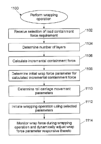
[0044] FIGURE 12 is a flowchart illustrating a sequence of steps in an
example routine for performing another wrapping operation in the control
system of
Fig. 8, but based upon operator input of a number of layers of packaging
material to
apply to a load.
[0045] FIGURES 13-23 are block diagrams of example displays capable of
being displayed by the control system of Fig. 8 when interacting with an
operator.
[0046] FIGURE 24 is a flowchart illustrating a sequence of steps in an
example routine for configuring a packaging material profile in the control
system of
Fig. 8.
[0047] FIGURES 25-33 are block diagrams of additional example displays
capable of being displayed by the control system of Fig. 8 when interacting
with an
operator.
[0048] FIGURE 34 is a flowchart illustrating a sequence of steps in an
example routine for performing a wrapping operation and dynamically adjusting
a
wrap force parameter during such an operation in the control system of Fig. 8.
12
CA 2936699 2017-10-27
[0049] FIGURE 35 is a flowchart illustrating an example implementation of
the dynamic wrap force parameter adjustment referenced in Fig. 34.
[0050] FIGURE 36 is a flowchart illustrating a sequence of steps in an
example routine for dynamically modifying a number of layers applied to a load
during a wrapping operation in the control system of Fig. 8.
[0051] FIGURE 37 is a flowchart illustrating a sequence of steps in an
example routine for performing a wrapping operation and dynamically adjusting
a
layer parameter during such an operation in the control system of Fig. 8.
[0052] FIGURE 38 is a flowchart illustrating a sequence of steps in an
example routine for performing wrapping operations and reducing packaging
material breaks during such operations in the control system of Fig. 8.
[0053] FIGURE 39 is a flowchart illustrating a sequence of steps in an
example routine for performing wrapping operations and self-calibrating
packaging
material in a wrapping apparatus during such operations in the control system
of
Fig. 8.
Detailed Description
[0054] Embodiments consistent with the invention utilize various techniques
to dynamically adjust a wrap force parameter to control a containment force
applied
to a load based on a monitored wrap force and/or reduce packaging material
breaks.
Prior to a discussion of the aforementioned concepts, however, a brief
discussion of
various types of wrapping apparatus within which the various techniques
disclosed
herein may be implemented is provided.
[0055] In addition, the disclosures of each of U.S. Pat. No. 4,418,510,
entitled "STRETCH WRAPPING APPARATUS AND PROCESS," and filed Apr. 17,
1981; U.S. Pat. No. 4,953,336, entitled "HIGH TENSILE WRAPPING APPARATUS,"
and filed Aug. 17, 1989; U.S. Pat. No. 4,503,658, entitled "FEEDBACK
CONTROLLED STRETCH WRAPPING APPARATUS AND PROCESS," and filed
Mar. 28, 1983; U.S. Pat. No. 4,676,048, entitled "SUPPLY CONTROL ROTATING
STRETCH WRAPPING APPARATUS AND PROCESS," and filed May 20, 1986;
U.S. Pat. No. 4,514,955, entitled "FEEDBACK CONTROLLED STRETCH
13
CA 2936699 2017-10-27
WRAPPING APPARATUS AND PROCESS," and filed Apr. 6, 1981; U.S. Pat. No.
6,748,718, entitled "METHOD AND APPARATUS FOR WRAPPING A LOAD," and
filed Oct. 31, 2002; U.S. Pat. No. 7,707,801, entitled "METHOD AND APPARATUS
FOR DISPENSING A PREDETERMINED FIXED AMOUNT OF PRE-STRETCHED
FILM RELATIVE TO LOAD GIRTH," filed Apr. 6, 2006; U.S. Pat. No. 8,037,660,
entitled "METHOD AND APPARATUS FOR SECURING A LOAD TO A PALLET
WITH A ROPED FILM WEB," and filed Feb. 23, 2007; U.S. Patent Application
Publication No. 2007/0204565, entitled "METHOD AND APPARATUS FOR
METERED PRE-STRETCH FILM DELIVERY," and filed Sep. 6, 2007; U.S. Pat. No.
7,779,607, entitled "WRAPPING APPARATUS INCLUDING METERED PRE-
STRETCH FILM DELIVERY ASSEMBLY AND METHOD OF USING," and filed Feb.
23, 2007; U.S. Patent Application Publication No. 2009/0178374, entitled
"ELECTRONIC CONTROL OF METERED FILM DISPENSING IN A WRAPPING
APPARATUS," and filed Jan. 7, 2009; U.S. Patent Application Publication No.
2011/0131927, entitled "DEMAND BASED WRAPPING," and filed Nov. 6, 2010; U.
S. Patent Application Publication No. 2012/0102886, entitled "METHODS AND
APPARATUS FOR EVALUATING PACKAGING MATERIALS AND DETERMINING
WRAP SETTINGS FOR WRAPPING MACHINES," and filed Oct. 28, 2011; U. S.
Patent Application Publication No. 2012/0102887, entitled "MACHINE GENERATED
WRAP DATA," and filed Oct. 28, 2011; U.S. provisional patent application S/N
61/718,429, entitled "ROTATION ANGLE-BASED WRAPPING," and filed Oct. 25,
2012; U.S. provisional patent application S/N 61/718,433, entitled "EFFECTIVE
CIRCUMFERENCE-BASED WRAPPING," and filed Oct. 25, 2012; U.S. patent
application S/N 14/052,929, entitled "ROTATION ANGLE-BASED WRAPPING," and
filed Oct. 25, 2013; U.S. patent application S/N 14/052,930, entitled
"EFFECTIVE
CIRCUMFERENCE-BASED WRAPPING," and filed Oct. 25, 2013; U.S. patent
application S/N 14/052,931, entitled "CORNER GEOMETRY-BASED WRAPPING,"
and filed Oct. 25, 2013; and U.S. provisional patent application S/N
61/764,107,
entitled "CONTAINMENT FORCE-BASED WRAPPING," and filed February 13,
2013.
14
CA 2936699 2017-10-27
Wrapping Apparatus Configurations
[0056] Fig. 1, for example, illustrates a rotating arm-type wrapping apparatus
100, which includes a roll carriage 102 mounted on a rotating arm 104. Roll
carriage
102 may include a packaging material dispenser 106. Packaging material
dispenser
106 may be configured to dispense packaging material 108 as rotating arm 104
rotates relative to a load 110 to be wrapped. In an exemplary embodiment,
packaging material dispenser 106 may be configured to dispense stretch wrap
packaging material. As used herein, stretch wrap packaging material is defined
as
material having a high yield coefficient to allow the material a large amount
of stretch
during wrapping. However, it is possible that the apparatuses and methods
disclosed
herein may be practiced with packaging material that will not be pre-stretched
prior
to application to the load. Examples of such packaging material include
netting,
strapping, banding, tape, etc. The invention is therefore not limited to use
with
stretch wrap packaging material.
[0057] Packaging material dispenser 106 may include a pre-stretch
assembly 112 configured to pre-stretch packaging material before it is applied
to
load 110 if pre-stretching is desired, or to dispense packaging material to
load 110
without pre-stretching. Pre-stretch assembly 112 may include at least one
packaging
material dispensing roller, including, for example, an upstream dispensing
roller 114
and a downstream dispensing roller 116. It is contemplated that pre-stretch
assembly 112 may include various configurations and numbers of pre-stretch
rollers,
drive or driven roller and idle rollers without departing from the spirit and
scope of the
invention.
[0058] The terms "upstream" and "downstream," as used in this application,
are intended to define positions and movement relative to the direction of
flow of
packaging material 108 as it moves from packaging material dispenser 106 to
load
110. Movement of an object toward packaging material dispenser 106, away from
load 110, and thus, against the direction of flow of packaging material 108,
may be
defined as "upstream." Similarly, movement of an object away from packaging
material dispenser 106, toward load 110, and thus, with the flow of packaging
material 108, may be defined as "downstream." Also, positions relative to load
110
(or a load support surface 118) and packaging material dispenser 106 may be
CA 2936699 2017-10-27
described relative to the direction of packaging material flow. For example,
when two
pre-stretch rollers are present, the pre-stretch roller closer to packaging
material
dispenser 106 may be characterized as the "upstream" roller and the pre-
stretch
roller closer to load 110 (or load support 118) and further from packaging
material
dispenser 106 may be characterized as the "downstream" roller.
[0059] A packaging material drive system 120, including, for example, an
electric motor 122, may be used to drive dispensing rollers 114 and 116. For
example, electric motor 122 may rotate downstream dispensing roller 116.
Downstream dispensing roller 116 may be operatively coupled to upstream
dispensing roller 114 by a chain and sprocket assembly, such that upstream
dispensing roller 114 may be driven in rotation by downstream dispensing
roller 116.
Other connections may be used to drive upstream roller 114 or, alternatively,
a
separate drive (not shown) may be provided to drive upstream roller 114.
[0060] Downstream of downstream dispensing roller 116 may be provided
one or more idle rollers 124, 126 that redirect the web of packaging material,
with the
most downstream idle roller 126 effectively providing an exit point 128 from
packaging material dispenser 102, such that a portion 130 of packaging
material 108
extends between exit point 128 and a contact point 132 where the packaging
material engages load 110 (or alternatively contact point 132' if load 110 is
rotated in
a counter-clockwise direction).
[0061] Wrapping apparatus 100 also includes a relative rotation assembly
134 configured to rotate rotating arm 104, and thus, packaging material
dispenser
106 mounted thereon, relative to load 110 as load 110 is supported on load
support
surface 118. Relative rotation assembly 134 may include a rotational drive
system
136, including, for example, an electric motor 138. It is contemplated that
rotational
drive system 136 and packaging material drive system 120 may run independently
of
one another. Thus, rotation of dispensing rollers 114 and 116 may be
independent of
the relative rotation of packaging material dispenser 106 relative to load
110. This
independence allows a length of packaging material 108 to be dispensed per a
portion of relative revolution that is neither predetermined or constant.
Rather, the
length may be adjusted periodically or continuously based on changing
conditions.
16
CA 2936699 2017-10-27
[0062] Wrapping apparatus 100 may further include a lift assembly 140. Lift
assembly 140 may be powered by a lift drive system 142, including, for
example, an
electric motor 144, that may be configured to move roll carriage 102
vertically
relative to load 110. Lift drive system 142 may drive roll carriage 102, and
thus
packaging material dispenser 106, upwards and downwards vertically on rotating
arm 104 while roll carriage 102 and packaging material dispenser 106 are
rotated
about load 110 by rotational drive system 136, to wrap packaging material
spirally
about load 110.
[0063] One or more of downstream dispensing roller 116, idle roller 124 and
idle roller 126 may include a corresponding sensor 146, 148, 150 to monitor
rotation
of the respective roller. In particular, rollers 116, 124 and/or 126, and/or
packaging
material 108 dispensed thereby, may be used to monitor a dispense rate of
packaging material dispenser 106, e.g., by monitoring the rotational speed of
rollers
116, 124 and/or 126, the number of rotations undergone by such rollers, the
amount
and/or speed of packaging material dispensed by such rollers, and/or one or
more
performance parameters indicative of the operating state of packaging material
drive
system 120, including, for example, a speed of packaging material drive system
120.
The monitored characteristics may also provide an indication of the amount of
packaging material 108 being dispensed and wrapped onto load 110. In addition,
in
some embodiments a sensor, e.g., sensor 148 or 150, may be used to detect a
break in the packaging material.
[0064] Wrapping apparatus also includes an angle sensor 152 for
determining an angular relationship between load 110 and packaging material
dispenser 106 about a center of rotation 154 (through which projects an axis
of
rotation that is perpendicular to the view illustrated in Fig. 1). Angle
sensor 152 may
be implemented, for example, as a rotary encoder, or alternatively, using any
number of alternate sensors or sensor arrays capable of providing an
indication of
the angular relationship and distinguishing from among multiple angles
throughout
the relative rotation, e.g., an array of proximity switches, optical encoders,
magnetic
encoders, electrical sensors, mechanical sensors, photodetectors, motion
sensors,
etc. The angular relationship may be represented in some embodiments in terms
of
degrees or fractions of degrees, while in other embodiments a lower resolution
may
17
CA 2936699 2017-10-27
be adequate. It will also be appreciated that an angle sensor consistent with
the
invention may also be disposed in other locations on wrapping apparatus 100,
e.g.,
about the periphery or mounted on arm 104 or roll carriage 102. In addition,
in some
embodiments angular relationship may be represented and/or measured in units
of
time, based upon a known rotational speed of the load relative to the
packaging
material dispenser, from which a time to complete a full revolution may be
derived
such that segments of the revolution time would correspond to particular
angular
relationships.
[0065] Additional sensors, such as a load distance sensor 156 and/or a film
angle sensor 158, may also be provided on wrapping apparatus 100. Load
distance
sensor 156 may be used to measure a distance from a reference point to a
surface
of load 110 as the load rotates relative to packaging material dispenser 106
and
thereby determine a cross-sectional dimension of the load at a predetermined
angular position relative to the packaging material dispenser. In one
embodiment,
load distance sensor 156 measures distance along a radial from center of
rotation
154, and based on the known, fixed distance between the sensor and the center
of
rotation, the dimension of the load may be determined by subtracting the
sensed
distance from this fixed distance. Sensor 156 may be implemented using various
types of distance sensors, e.g., a photoeye, proximity detector, laser
distance
measurer, ultrasonic distance measurer, electronic rangefinder, and/or any
other
suitable distance measuring device. Exemplary distance measuring devices may
include, for example, an IFM Effector 01D100 and a Sick UM30-213118 (6036923).
[0066] Film angle sensor 158 may be used to determine a film angle for
portion 130 of packaging material 108, which may be relative, for example, to
a
radial (not shown in Fig. 1) extending from center of rotation 154 to exit
point 128
(although other reference lines may be used in the alternative).
[0067] In one embodiment, film angle sensor 158 may be implemented using
a distance sensor, e.g., a photoeye, proximity detector, laser distance
measurer,
ultrasonic distance measurer, electronic rangefinder, and/or any other
suitable
distance measuring device. In one embodiment, an IFM Effector 010100 and a
Sick
UM30-213118 (6036923) may be used for film angle sensor 158. In other
embodiments, film angle sensor 158 may be implemented mechanically, e.g.,
using
18
CA 2936699 2017-10-27
a cantilevered or rockered follower arm having a free end that rides along the
surface of portion 130 of packaging material 108 such that movement of the
follower
arm tracks movement of the packaging material. In still other embodiments, a
film
angle sensor may be implemented by a force sensor that senses force changes
resulting from movement of portion 130 through a range of film angles, or a
sensor
array (e.g., an image sensor) that is positioned above or below the plane of
portion
130 to sense an edge of the packaging material. Wrapping apparatus 100 may
also
include additional components used in connection with other aspects of a
wrapping
operation. For example, a clamping device 159 may be used to grip the leading
end
of packaging material 108 between cycles. In addition, a conveyor (not shown)
may
be used to convey loads to and from wrapping apparatus 100. Other components
commonly used on a wrapping apparatus will be appreciated by one of ordinary
skill
in the art having the benefit of the instant disclosure.
[0068] An exemplary schematic of a control system 160 for wrapping
apparatus 100 is shown in Fig. 2. Motor 122 of packaging material drive system
120, motor 138 of rotational drive system 136, and motor 144 of lift drive
system 142
may communicate through one or more data links 162 with a rotational drive
variable
frequency drive ("VFD") 164, a packaging material drive VFD 166, and a lift
drive
VFD 168, respectively. Rotational drive VFD 164, packaging material drive VFD
166,
and lift drive VFD 168 may communicate with controller 170 through a data link
172.
It should be understood that rotational drive VFD 164, packaging material
drive VFD
166, and lift drive VFD 168 may produce outputs to controller 170 that
controller 170
may use as indicators of rotational movement. For example, packaging material
drive VFD 166 may provide controller 170 with signals similar to signals
provided by
sensor 146, and thus, sensor 146 may be omitted to cut down on manufacturing
costs.
[0069] Controller 170 may include hardware components and/or software
program code that allow it to receive, process, and transmit data. It is
contemplated
that controller 170 may be implemented as a programmable logic controller
(PLC), or
may otherwise operate similar to a processor in a computer system. Controller
170
may communicate with an operator interface 174 via a data link 176. Operator
interface 174 may include a display or screen and controls that provide an
operator
19
CA 2936699 2017-10-27
with a way to monitor, program, and operate wrapping apparatus 100. For
example,
an operator may use operator interface 174 to enter or change predetermined
and/or
desired settings and values, or to start, stop, or pause the wrapping cycle.
Controller
170 may also communicate with one or more sensors, e.g., sensors 146, 148,
150,
152, 154 and 156, as well as others not illustrated in Fig. 2, through a data
link 178,
thus allowing controller 170 to receive performance related data during
wrapping. It
is contemplated that data links 162, 172, 176, and 178 may include any
suitable
wired and/or wireless communications media known in the art.
[0070] As noted above, sensors 146, 148, 150, 152 may be configured in a
number of manners consistent with the invention. In one embodiment, for
example,
sensor 146 may be configured to sense rotation of downstream dispensing roller
116, and may include one or more magnetic transducers 180 mounted on
downstream dispensing roller 116, and a sensing device 182 configured to
generate
a pulse when the one or more magnetic transducers 180 are brought into
proximity
of sensing device 182. Alternatively, sensor assembly 146 may include an
encoder
configured to monitor rotational movement, and capable of producing, for
example,
360 or 720 signals per revolution of downstream dispensing roller 116 to
provide an
indication of the speed or other characteristic of rotation of downstream
dispensing
roller 116. The encoder may be mounted on a shaft of downstream dispensing
roller
116, on electric motor 122, and/or any other suitable area. One example of a
sensor
assembly that may be used is an Encoder Products Company model 15H optical
encoder. Other suitable sensors and/or encoders may be used for monitoring,
such
as, for example, optical encoders, magnetic encoders, electrical sensors,
mechanical
sensors, photodetectors, and/or motion sensors.
[0071] Likewise, for sensors 148 and 150, magnetic transducers 184, 186
and sensing devices 188, 190 may be used to monitor rotational movement, while
for
sensor 152, a rotary encoder may be used to determine the angular relationship
between the load and packaging material dispenser. Any of the aforementioned
alternative sensor configurations may be used for any of sensors 146, 148,
150, 152,
154 and 156 in other embodiments, and as noted above, one or more of such
sensors may be omitted in some embodiments. Additional sensors capable of
CA 2936699 2017-10-27
monitoring other aspects of the wrapping operation may also be coupled to
controller
170 in other embodiments.
[0072] For the purposes of the invention, controller 170 may represent
practically any type of computer, computer system, controller, logic
controller, or
other programmable electronic device, and may in some embodiments be
implemented using one or more networked computers or other electronic devices,
whether located locally or remotely with respect to wrapping apparatus 100.
Controller 170 typically includes a central processing unit including at least
one
microprocessor coupled to a memory, which may represent the random access
memory (RAM) devices comprising the main storage of controller 170, as well as
any
supplemental levels of memory, e.g., cache memories, non-volatile or backup
memories (e.g., programmable or flash memories), read-only memories, etc. In
addition, the memory may be considered to include memory storage physically
located elsewhere in controller 170, e.g., any cache memory in a processor in
CPU
52, as well as any storage capacity used as a virtual memory, e.g., as stored
on a
mass storage device or on another computer or electronic device coupled to
controller 170. Controller 170 may also include one or more mass storage
devices,
e.g., a floppy or other removable disk drive, a hard disk drive, a direct
access
storage device (DASD), an optical drive (e.g., a CD drive, a DVD drive, etc.),
and/or
a tape drive, among others. Furthermore, controller 170 may include an
interface
with one or more networks (e.g., a LAN, a WAN, a wireless network, and/or the
Internet, among others) to permit the communication of information to the
components in wrapping apparatus 100 as well as with other computers and
electronic devices. Controller 170 operates under the control of an operating
system, kernel and/or firmware and executes or otherwise relies upon various
computer software applications, components, programs, objects, modules, data
structures, etc. Moreover, various applications, components, programs,
objects,
modules, etc. may also execute on one or more processors in another computer
coupled to controller 170, e.g., in a distributed or client-server computing
environment, whereby the processing required to implement the functions of a
computer program may be allocated to multiple computers over a network.
21
CA 2936699 2017-10-27
[0073] In general, the routines executed to implement the embodiments of
the invention, whether implemented as part of an operating system or a
specific
application, component, program, object, module or sequence of instructions,
or
even a subset thereof, will be referred to herein as "computer program code,"
or
simply "program code." Program code typically comprises one or more
instructions
that are resident at various times in various memory and storage devices in a
computer, and that, when read and executed by one or more processors in a
computer, cause that computer to perform the steps necessary to execute steps
or
elements embodying the various aspects of the invention. Moreover, while the
invention has and hereinafter will be described in the context of fully
functioning
controllers, computers and computer systems, those skilled in the art will
appreciate
that the various embodiments of the invention are capable of being distributed
as a
program product in a variety of forms, and that the invention applies equally
regardless of the particular type of computer readable media used to actually
carry
out the distribution.
[0074] Such computer readable media may include computer readable
storage media and communication media. Computer readable storage media is non-
transitory in nature, and may include volatile and non-volatile, and removable
and
non-removable media implemented in any method or technology for storage of
information, such as computer-readable instructions, data structures, program
modules or other data. Computer readable storage media may further include
RAM,
ROM, erasable programmable read-only memory (EPROM), electrically erasable
programmable read-only memory (EEPROM), flash memory or other solid state
memory technology, CD-ROM, digital versatile disks (DVD), or other optical
storage,
magnetic cassettes, magnetic tape, magnetic disk storage or other magnetic
storage
devices, or any other medium that can be used to store the desired information
and
which can be accessed by controller 170. Communication media may embody
computer readable instructions, data structures or other program modules. By
way
of example, and not limitation, communication media may include wired media
such
as a wired network or direct-wired connection, and wireless media such as
acoustic,
RF, infrared and other wireless media. Combinations of any of the above may
also
be included within the scope of computer readable media.
22
CA 2936699 2017-10-27
[0075] Various program code described hereinafter may be identified based
upon the application within which it is implemented in a specific embodiment
of the
invention. However, it should be appreciated that any particular program
nomenclature that follows is used merely for convenience, and thus the
invention
should not be limited to use solely in any specific application identified
and/or implied
by such nomenclature. Furthermore, given the typically endless number of
manners
in which computer programs may be organized into routines, procedures,
methods,
modules, objects, and the like, as well as the various manners in which
program
functionality may be allocated among various software layers that are resident
within
a typical computer (e.g., operating systems, libraries, API's, applications,
applets,
etc.), it should be appreciated that the invention is not limited to the
specific
organization and allocation of program functionality described herein.
[0076] Now turning to Fig. 3, a rotating ring-type wrapping apparatus 200 is
illustrated. Wrapping apparatus 200 may include elements similar to those
shown in
relation to wrapping apparatus 100 of Fig. 1, including, for example, a roll
carriage
202 including a packaging material dispenser 206 configured to dispense
packaging
material 208 during relative rotation between roll carriage 202 and a load 210
disposed on a load support 218. However, a rotating ring 204 is used in
wrapping
apparatus 200 in place of rotating arm 104 of wrapping apparatus 100. In many
other respects, however, wrapping apparatus 200 may operate in a manner
similar
to that described above with respect to wrapping apparatus 100.
[0077] Packaging material dispenser 206 may include a pre-stretch
assembly 212 including an upstream dispensing roller 214 and a downstream
dispensing roller 216, and a packaging material drive system 220, including,
for
example, an electric motor 222, may be used to drive dispensing rollers 214
and
216. Downstream of downstream dispensing roller 216 may be provided one or
more idle rollers 224, 226, with the most downstream idle roller 226
effectively
providing an exit point 228 from packaging material dispenser 206, such that a
portion 230 of packaging material 208 extends between exit point 228 and a
contact
point 232 where the packaging material engages load 210.
[0078] Wrapping apparatus 200 also includes a relative rotation assembly
234 configured to rotate rotating ring 204, and thus, packaging material
dispenser
23
CA 2936699 2017-10-27
206 mounted thereon, relative to load 210 as load 210 is supported on load
support
surface 218. Relative rotation assembly 234 may include a rotational drive
system
236, including, for example, an electric motor 238. Wrapping apparatus 200 may
further include a lift assembly 240, which may be powered by a lift drive
system 242,
including, for example, an electric motor 244, that may be configured to move
rotating ring 204 and roll carriage 202 vertically relative to load 210.
[0079] In addition, similar to wrapping apparatus 100, wrapping apparatus
200 may include sensors 246, 248, 250 on one or more of downstream dispensing
roller 216, idle roller 224 and idle roller 226. Furthermore, an angle sensor
252 may
be provided for determining an angular relationship between load 210 and
packaging
material dispenser 206 about a center of rotation 254 (through which projects
an axis
of rotation that is perpendicular to the view illustrated in Fig. 3), and in
some
embodiments, one or both of a load distance sensor 256 and a film angle sensor
258
may also be provided. Sensor 252 may be positioned proximate center of
rotation
254, or alternatively, may be positioned at other locations, such as proximate
rotating
ring 204. Wrapping apparatus 200 may also include additional components used
in
connection with other aspects of a wrapping operation, e.g., a clamping device
259
may be used to grip the leading end of packaging material 208 between cycles.
[0080] Fig. 4 likewise shows a turntable-type wrapping apparatus 300, which
may also include elements similar to those shown in relation to wrapping
apparatus
100 of Fig. 1. However, instead of a roll carriage 102 that rotates around a
fixed load
110 using a rotating arm 104, as in Fig. 1, wrapping apparatus 300 includes a
rotating turntable 304 functioning as a load support 318 and configured to
rotate load
310 about a center of rotation 354 (through which projects an axis of rotation
that is
perpendicular to the view illustrated in Fig. 4) while a packaging material
dispenser
306 disposed on a dispenser support 302 remains in a fixed location about
center of
rotation 354 while dispensing packaging material 308. In many other respects,
however, wrapping apparatus 300 may operate in a manner similar to that
described
above with respect to wrapping apparatus 100.
[0081] Packaging material dispenser 306 may include a pre-stretch
assembly 312 including an upstream dispensing roller 314 and a downstream
dispensing roller 316, and a packaging material drive system 320, including,
for
24
CA 2936699 2017-10-27
example, an electric motor 322, may be used to drive dispensing rollers 314
and
316, and downstream of downstream dispensing roller 316 may be provided one or
more idle rollers 324, 326, with the most downstream idle roller 326
effectively
providing an exit point 328 from packaging material dispenser 306, such that a
portion 330 of packaging material 308 extends between exit point 328 and a
contact
point 332 (or alternatively contact point 332' if load 310 is rotated in a
counter-
clockwise direction) where the packaging material engages load 310.
[0082] Wrapping apparatus 300 also includes a relative rotation assembly
334 configured to rotate turntable 304, and thus, load 310 supported thereon,
relative to packaging material dispenser 306. Relative rotation assembly 334
may
include a rotational drive system 336, including, for example, an electric
motor 338.
Wrapping apparatus 300 may further include a lift assembly 340, which may be
powered by a lift drive system 342, including, for example, an electric motor
344, that
may be configured to move dispenser support 302 and packaging material
dispenser
306 vertically relative to load 310.
[0083] In addition, similar to wrapping apparatus 100, wrapping apparatus
300 may include sensors 346, 348, 350 on one or more of downstream dispensing
roller 316, idle roller 324 and idle roller 326. Furthermore, an angle sensor
352 may
be provided for determining an angular relationship between load 310 and
packaging
material dispenser 306 about a center of rotation 354, and in some
embodiments,
one or both of a load distance sensor 356 and a film angle sensor 358 may also
be
provided. Sensor 352 may be positioned proximate center of rotation 354, or
alternatively, may be positioned at other locations, such as proximate the
edge of
turntable 304. Wrapping apparatus 300 may also include additional components
used in connection with other aspects of a wrapping operation, e.g., a
clamping
device 359 may be used to grip the leading end of packaging material 308
between
cycles.
[0084] Each of wrapping apparatus 200 of Fig. 3 and wrapping apparatus
300 of Fig. 4 may also include a controller (not shown) similar to controller
170 of
Fig. 2, and receive signals from one or more of the aforementioned sensors and
control packaging material drive system 220, 320 during relative rotation
between
load 210, 310 and packaging material dispenser 206, 306.
CA 2936699 2017-10-27
[0085] Those skilled in the art will recognize that the exemplary
environments illustrated in Figs. 1-4 are not intended to limit the present
invention.
Indeed, those skilled in the art will recognize that other alternative
environments may
be used without departing from the scope of the invention.
Wrapping Operation
[0086] During a typical wrapping operation, a clamping device, e.g., as
known in the art, is used to position a leading edge of the packaging material
on the
load such that when relative rotation between the load and the packaging
material
dispenser is initiated, the packaging material will be dispensed from the
packaging
material dispenser and wrapped around the load. In addition, where
prestretching is
used, the packaging material is stretched prior to being conveyed to the load.
The
dispense rate of the packaging material is controlled during the relative
rotation
between the load and the packaging material, and a lift assembly controls the
position, e.g., the height, of the web of packaging material engaging the load
so that
the packaging material is wrapped in a spiral manner around the load from the
base
or bottom of the load to the top. Multiple layers of packaging material may be
wrapped around the load over multiple passes to increase overall containment
force,
and once the desired amount of packaging material is dispensed, the packaging
material is severed to complete the wrap.
[0087] In the illustrated embodiments, to control the overall containment
force of the packaging material applied to the load, both the wrap force and
the
position of the web of packaging material are both controlled to provide the
load with
a desired overall containment force. The mechanisms by which each of these
aspects of a wrapping operation are controlled are provided below.
Wrap Force Control
[0088] In many wrapping applications, the rate at which packaging material
is dispensed by a packaging material dispenser of a wrapping apparatus may be
controlled based on a wrap force parameter such as desired payout percentage,
which in general relates to the amount of wrap force applied to the load by
the
packaging material during wrapping. Further details regarding the concept of
payout
26
CA 2936699 2017-10-27
percentage may be found, for example, in the aforementioned U.S. Pat. No.
7,707,801.
[0089] In many embodiments, for example, a payout percentage may have a
range of about 80% to about 120%. Decreasing the payout percentage slows the
rate at which packaging material exits the packaging material dispenser
compared to
the relative rotation of the load such that the packaging material is pulled
tighter
around the load, thereby increasing wrap force, and as a consequence, the
overall
containment force applied to the load. In contrast, increasing the payout
percentage
decreases the wrap force. For the purposes of simplifying the discussion
hereinafter, however, a payout percentage of 100% is initially assumed.
[0090] It will be appreciated, however, that other metrics may be used as an
alternative to payout percentage to reflect the relative amount of wrap force
to be
applied during wrapping, so the invention is not so limited. In particular, to
simplify
the discussion, the term "wrap force" will be used herein to generically refer
to any
metric or parameter in a wrapping apparatus that may be used to control how
tight
the packaging material is pulled around a load at a given instant. Wrap force,
as
such, may be based on the amount of tension induced in a web of packaging
material extending between the packaging material dispenser and the load,
which in
some embodiments may be measured and controlled directly, e.g., through the
use
of an electronic load cell coupled to a roller over which the packaging
material
passes, a spring-loaded dancer interconnected with a sensor, a torque control
device, or any other suitable sensor capable of measuring force or tension in
a web
of packaging material.
[0091] On the other hand, because the amount of tension that is induced in
a web of packaging material is fundamentally based upon the relationship
between
the feed rate of the packaging material and the rate of relative rotation of
the load
(i.e., the demand rate of the load), wrap force may also refer to various
metrics or
parameters related to the rate at which the packaging material is dispensed by
a
packaging material dispenser.
[0092] Thus, a payout percentage, which relates the rate at which the
packaging material is dispensed by the packaging material dispenser to the
rate at
27
CA 2936699 2017-10-27
which the load is rotated relative to the packaging material dispenser, may be
a
suitable wrap force parameter in some embodiments. Alternatively, a dispense
rate,
e.g., in terms of the absolute or relative linear rate at which packaging
material exits
the packaging material dispenser, or the absolute or relative rotational rate
at which
an idle or driven roller in the packaging material dispenser or otherwise
engaging the
packaging material rotates, may also be a suitable wrap force parameter in
some
embodiments.
[0093] To control wrap force in a wrapping apparatus, a number of different
control methodologies may be used. In some embodiments, for example, the wrap
force may be controlled directly based on a wrap force parameter such as
payout
percentage, as noted above, such that the rate of dispensing of packaging
material
is scaled relative to the rate of relative rotation of the load. As another
example, in
some embodiments of the invention, the effective circumference of a load may
be
used to dynamically control the rate at which packaging material is dispensed
to a
load when wrapping the load with packaging material during relative rotation
established between the load and a packaging material dispenser, and thus
control
the wrap force applied to the load by the packaging material.
[0094] Fig. 5, for example, functionally illustrates a wrapping apparatus 400
in which a load support 402 and packaging material dispenser 404 are adapted
for
relative rotation with one another to rotate a load 406 about a center of
rotation 408
and thereby dispense a packaging material 410 for wrapping around the load. In
this
illustration, the relative rotation is in a clockwise direction relative to
the load (i.e., the
load rotates clockwise relative to the packaging material dispenser, while the
packaging material dispenser may be considered to rotate in a counter-
clockwise
direction around the load).
[0095] In embodiments consistent with the invention, the effective
circumference of a load throughout relative rotation is indicative of an
effective
consumption rate of the load, which is in turn indicative of the amount of
packaging
material being "consumed" by the load as the load rotates relative to the
packaging
dispenser. In particular, effective consumption rate, as used herein,
generally refers
to a rate at which packaging material would need to be dispensed by the
packaging
material dispenser in order to substantially match the tangential velocity of
a tangent
28
CA 2936699 2017-10-27
circle that is substantially centered at the center of rotation of the load
and
substantially tangent to a line substantially extending between a first point
proximate
to where the packaging material exits the dispenser and a second point
proximate to
where the packaging material engages the load. This line is generally
coincident
with the web of packaging material between where the packaging material exits
the
dispenser and where the packaging material engages the load.
[0096] As shown in Fig. 5, for example, an idle roller 412 defines an exit
point 414 for packaging material dispenser 404, such that a portion of web 416
of
packaging material 410 extends between this exit point 414 and an engagement
point 418 at which the packaging material 410 engages load 406. In this
arrangement, a tangent circle 420 is tangent to portion 416 and is centered at
center
of rotation 408.
[0097] The tangent circle has a circumference CTc, which for the purposes of
this invention, is referred to as the "effective circumference" of the load.
Likewise,
other dimensions of the tangent circle, e.g., the radius RTC and diameter DTc,
may be
respectively referred to as the "effective radius" and "effective diameter" of
the load.
[0098] It has been found that for a load having a non-circular cross-section,
as the load rotates relative to the dispenser about center of rotation 408
(through
which an axis of rotation extends generally perpendicular to the view shown in
Fig.
5), the size (i.e., the circumference, radius and diameter) of tangent circle
420
dynamically varies, and that the size of tangent circle 420 throughout the
rotation
effectively models, at any given angular position of the load relative to the
dispenser,
a rate at which packaging material should be dispensed in order to match the
consumption rate of the load, i.e., where the dispense rate in terms of linear
velocity
(represented by arrow VD) is substantially equal to the tangential velocity of
the
tangent circle (represented by arrow Vc). Thus, in situations where a payout
percentage of 100% is desired, the desired dispense rate of the packaging
material
may be set to substantially track the dynamically changing tangential velocity
of the
tangent circle.
[0099] Of note, the tangent circle is dependent not only on the dimensions of
the load (i.e., the length L and width W), but also the offset of the
geometric center
29
CA 2936699 2017-10-27
422 of the load from the center of rotation 408, illustrated in Fig. 5 as OL
and Ow.
Given that in many applications, a load will not be perfectly centered when it
is
placed or conveyed onto the load support, the dimensions of the load, by
themselves, typically do not present a complete picture of the effective
consumption
rate of the load. Nonetheless, as will become more apparent below, the
calculation
of the dimensions of the tangent circle, and thus the effective consumption
rate, may
be determined without determining the actual dimensions and/or offset of the
load in
many embodiments.
[00100] It has been found that this tangent circle, when coupled with the web
of packaging material and the drive roller (e.g., drive roller 424), functions
in much
the same manner as a belt drive system, with tangent circle 420 functioning as
the
driver pulley, dispenser drive roller 424 functioning as the follower pulley,
and web
416 of packaging material functioning as the belt. For example, let Nd be the
rotational velocity of a driver pulley in RPM, Nf be the rotational velocity
of a follower
pulley in RPM, Rd be the radius of the driver pulley and Rf be the radius of
the
follower pulley. Consider the length of belt that passes over each of the
driver pulley
and the follower pulley in one minute, which is equal to the circumference of
the
respective pulley (diameter * -rr, or radius * 2-rr) multiplied by the
rotational velocity:
Ld 21T*Rd * Nd (1)
Lf = 2ff*Rf * Nf (2)
[00101] where Ld is the length of belt that passes over the driver pulley in
one
minute, and L1 is the length of belt that passes over the follower pulley in
one minute.
[00102] In this theoretical system, the point at which neither pulley applied
a
tensile or compressive force to the belt (which generally corresponds to a
payout
percentage of 100%) would be achieved when the tangential velocities, i.e.,
the
linear velocities at the surfaces or rims of the pulleys, were equal. Put
another way,
when the length of belt that passes over each pulley over the same time period
is
equal, i.e., Ld = Lf. Therefore:
CA 2936699 2017-10-27
2n-*Rd * Nd = 2TT*Rf " Nf (3)
[00103] Consequently, the velocity ratio VR of the rotational velocities of
the
driver and follower pulleys is:
Nd Rf
VR = ¨= ¨ (4)
N f Rd
[00104] Alternatively, the velocity ratio may be expressed in terms of the
ratio
of diameters or of circumferences:
Nd Df
VR = ¨ ¨ (5)
N f Dd
Nd Cf
VR = ¨ ¨ (6)
N f Cd
[00105] where Df, Dd are the respective diameters of the follower and driver
pulleys, and Cf, Cd are the respective circumferences of the follower and
driver
pulleys.
[00106] Returning to equations (1) and (2) above, the values Ld and Lf
represent the length of belt that passes the driver and follower pulleys in
one minute.
Thus, when the tangent circle for the load is considered a driver pulley, the
effective
consumption rate (ECR) may be considered to be equal to the length of
packaging
material that passes the tangent circle in a fixed amount of time, e.g., per
minute:
ECR = CTc * Nrc = 2TT*R7-c* NTC (7)
31
CA 2936699 2017-10-27
[00107] where C10 is the circumference of the tangent circle, N10 is the
rotational velocity of the tangent circle (e.g., in revolutions per minute
(RPM)), and
RTC is the radius of the tangent circle.
[00108] Therefore, given a known rotational velocity for the load, a known
circumference of the tangent circle at a given instant and a known
circumference for
the drive roller, the rotational velocity of the drive roller necessary to
provide a
dispense rate that substantially matches the effective consumption rate is:
CTC
NDR= (8)
CDR
[00109] where NDR is the rotational rate of the drive roller, CTC is the
circumference of the tangent circle and the effective circumference of the
load, CDR
is the circumference of the drive roller and NL is the rotational rate of the
load
relative to the dispenser.
[00110] In addition, should it be desirable to scale the rotational rate of
the
drive roller to provide a controlled payout percentage (PP), and thereby
provide a
desired containment force and/or a desired packaging material use efficiency,
equation (8) may be modified as follows:
CTC
NDR= AIL PP (9)
CDR
It should also be noted that, despite the fact that the dispense rate varies
throughout
the relative rotation based upon the effective circumference of the load, the
dispense
rate is controlled at least in part based upon a wrap force parameter (here,
payout
percentage).
[00111] The manner in which the dimensions (i.e., circumference, diameter
and/or radius) of the tangent circle may be calculated or otherwise determined
may
vary in different embodiments. For example, as illustrated in Fig. 6, a wrap
speed
model 500, representing the control algorithm by which to drive a packaging
material
32
CA 2936699 2017-10-27
dispenser to dispense packaging material at a desired dispense rate during
relative
rotation with a load, may be responsive to a number of different control
inputs.
[00112] In some embodiments, for example, a sensed film angle (block 502)
may be used to determine various dimensions of a tangent circle, e.g.,
effective
radius (block 504) and/or effective circumference (block 506). As shown in
Fig. 5, for
example, a film angle FA may be defined as the angle at exit point 414 between
portion 416 of packaging material 410 (to which tangent circle 420 is tangent)
and a
radial or radius 426 extending from center of rotation 408 to exit point 414.
[00113] Returning to Fig. 6, the film angle sensed in block 502, e.g., using
an
encoder and follower arm or other electronic sensor, is used to determine one
or
more dimensions of the tangent circle (e.g., effective radius, effective
circumference
and/or effective diameter), and from these determined dimensions, a wrap speed
control algorithm 508 determines a dispense rate. In many embodiments, wrap
speed control algorithm 508 also utilizes the angular relationship between the
load
and the packaging material dispenser, i.e., the sensed rotational position of
the load,
as an input such that, for any given rotational position or angle of the load
(e.g., at
any of a plurality of angles defined in a full revolution), a desired dispense
rate for
the determined tangent circle may be determined.
[00114] Alternatively or in addition to the use of sensed film angle, various
additional inputs may be used to determine dimensions of a tangent circle. As
shown in block 512, for example, a film speed sensor, such as an optical or
magnetic
encoder on an idle roller, may be used to determine the speed of the packaging
material as the packaging material exits the packaging material dispenser. In
addition, as shown in block 514, a laser or other distance sensor may be used
to
determine a load distance (i.e., the distance between the surface of the load
at a
particular rotational position and a reference point about the periphery of
the load).
Furthermore, as shown in block 516, the dimensions of the load, e.g., length,
width
and/or offset, may either be input manually by a user, may be received from a
database or other electronic data source, or may be sensed or measured.
[00115] From any or all of these inputs, one or more dimensions of the load,
such as corner contact angles (block 518), corner contact radials (block 520),
and/or
33
CA 2936699 2017-10-27
corner radials (block 522) may be used to determine a calculated film angle
(block
524), such that this calculated film angle may be used in lieu of or in
addition to any
sensed film angle to determine one or more dimensions of the tangent circle.
Thus,
the calculated film angle may be used by the wrap speed control algorithm in a
similar manner to the sensed film angle described above. Moreover, in some
embodiments additional modifications may be applied to wrap speed control
algorithm 508 to provide more accurate control over the dispense rate. As
shown in
block 526, for example, a compensation may be performed to address system lag.
In some embodiments, for example, a controlled intervention may be performed
to
effectively anticipate contact of a corner of the load with the packaging
material. In
addition, in some embodiments, a rotational shift may be performed to better
align
collected data with the control algorithm and thereby account for various lags
in the
system.
[00116] Additional details regarding effective circumference-based control
may be found in the aforementioned U.S. provisional patent applications SIN
61/718,429 and SIN 61/718,433. In addition, as noted above other manners of
directly or indirectly controlling wrap force may be used in other embodiments
without departing from the spirit and scope of the invention, including
various
techniques and variations disclosed in the aforementioned provisional patent
applications, as well as other wrap speed or wrap force-based control
packaging
material dispense techniques known in the art.
Web Position Control
[00117] As noted above, during a wrapping operation, the position of the web
of packaging material is typically controlled to wrap the load in a spiral
manner. Fig.
7, for example, illustrates a turntable-type wrapping apparatus 600 similar to
wrapping apparatus 300 of Fig. 4, including a load support 602 configured as a
rotating turntable 604 for supporting a load 606. Turntable 604 rotates about
an axis
of rotation 608, e.g., in a counter-clockwise direction as shown in Fig. 7.
[00118] A packaging material dispenser 610, including a roll carriage 612, is
configured for movement along a direction 614 by a lift mechanism 616. Roll
carriage 612 supports a roll 618 of packaging material, which during a
wrapping
34
CA 2936699 2017-10-27
operation includes a web 620 extending between packaging material dispenser
610
and load 606.
[00119] Direction 614 is generally parallel to an axis about which packaging
material is wrapped around load 606, e.g., axis 608, and movement of roll
carriage
612, and thus web 620, along direction 614 during a wrapping operation enables
packaging material to be wrapped spirally around the load.
[00120] In the illustrated embodiment, it is desirable to provide at least a
minimum number of layers of packaging material within a contiguous region on a
load. For example, load 606 includes opposing ends along axis 608, e.g., a top
622
and bottom 624 for a load wrapped about a vertically oriented axis 608, and it
may
be desirable to wrap packaging material between two positions 626 and 628
defined
along direction 614 and respectively proximate top 622 and bottom 624.
Positions
626, 628 define a region 630 therebetween that, in the illustrated
embodiments, is
provided with at least a minimum number of layers of packaging material
throughout.
[00121] The position of roll carriage 612 may be sensed using a sensing
device (not shown in Fig. 7), which may include any suitable reader, encoder,
transducer, detector, or sensor capable of determining the position of the
roll
carriage, another portion of the packaging material dispenser, or of the web
of
packaging material itself relative to load 606 along direction 614. It will be
appreciated that while a vertical direction 614 is illustrated in Fig. 7, and
thus the
position of roll carriage 612 corresponds to a height, in other embodiments
where a
load is wrapped about an axis other than a vertical axis, the position of the
roll
carriage may not be related to a height.
[00122] Control of the position of roll carriage 612, as well as of the other
drive systems in wrapping apparatus 600, is provided by a controller 632, the
details
of which are discussed in further detail below.
Containment Force-Based Wrapping
[00123] Conventionally, stretch wrapping machines have controlled the
manner in which packaging material is wrapped around a load by offering
control
input for the number of bottom wraps placed at the base of a load, the number
of top
CA 2936699 2017-10-27
wraps placed at the top of the load, and the speed of the roll carriage in the
up and
down traverse to manage overlaps of the spiral wrapped film. In some designs,
these controls have been enhanced by controlling the overlap inches during the
up
and down travel taking into consideration the relative speed of rotation and
roll
carriage speed.
[00124] However, it has been found that conventional control inputs often do
not provide optimal performance, as such control inputs often do not evenly
distribute the containment forces on all areas of a load, and often leave some
areas
with insufficient containment force. Often, this is due to the relatively
complexity of
the control inputs and the need for experienced operators. Particularly with
less
experienced operators, operators react to excessive film breaks by reducing
wrap
force and inadvertently lowering cumulative containment forces below desirable
levels.
[00125] Some embodiments consistent with the invention, on the other hand,
may utilize a containment force-based wrap control to simplify control over
wrap
parameters and facilitate even distribution of containment force applied to a
load. In
particular, in some embodiments of the invention, an operator specifies a load
containment force requirement that is used, in combination with one or more
attributes of the packaging material being used to wrap the load, to control
the
dispensing of packaging material to the load.
[00126] A load containment force requirement, for example, may include a
minimum overall containment force to be applied over all concerned areas of a
load
(e.g., all areas over which packaging material is wrapped around the load). In
some
embodiments, a load containment force requirement may also include different
minimum overall containment forces for different areas of a load, a desired
range of
containment forces for some or all areas of a load, a maximum containment
force for
some or all areas of a load.
[00127] A packaging material attribute may include, for example, an
incremental containment force/revolution (ICF) attribute, which is indicative
of the
amount of containment force added to a load in a single revolution of
packaging
material around the load. The ICF attribute may be related to a wrap force or
payout
36
CA 2936699 2017-10-27
percentage, such that, for example, the ICF attribute is defined as a function
of the
wrap force or payout percentage at which the packaging material is being
applied. In
some embodiments, the ICF attribute may be linearly related to payout
percentage,
and include an incremental containment force at 100% payout percentage along
with
a slope that enables the incremental containment force to be calculated for
any
payout percentage. Alternatively, the ICF attribute may be defined with a more
complex function, e.g., s-curve, interpolation, piecewise linear, exponential,
multi-
order polynomial, logarithmic, moving average, power, or other regression or
curve
fitting techniques. It will be appreciated that other attributes associated
with the
tensile strength of the packaging material may be used in the alternative.
[00128] Other packaging material attributes may include attributes associated
with the thickness and/or weight of the packaging material, e.g., specified in
terms of
weight per unit length, such as weight in ounces per 1000 inches. Still other
packaging material attributes may include a wrap force limit attributes,
indicating, for
example, a maximum wrap force or range of wrap forces with which to use the
packaging material (e.g., a minimum payout percentage), a width attribute
indicating
the width (e.g., in inches) of the packaging material, as well as additional
identifying
attributes of a packaging material, e.g., manufacturer, model, composition,
coloring,
etc.
[00129] A load containment force requirement and a packaging material
attribute may be used in a wrap control consistent with the invention to
determine
one or both of a wrap force to be used when wrapping a load with packaging
material and a number of layers of packaging material to be applied to the
load to
meet the load containment force requirement. The wrap force and number of
layers
may be represented respectively by wrap force and layer parameters. The wrap
force parameter may specify, for example, the desired wrap force to be applied
to
the load, e.g., in terms of payout percentage, or in terms of a dispense rate
or force.
[00130] The layer parameter may specify, for example, a minimum number of
layers of packaging material to be dispensed throughout a contiguous region of
a
load. In this regard, a minimum number of layers of three, for example, means
that
at any point on the load within a contiguous region wrapped with packaging
material,
at least three overlapping layers of packaging material will overlay that
point. A layer
37
CA 2936699 2017-10-27
parameter may also specify different number of layers for different portions
of a load,
and may include, for example, additional layers proximate the top and/or
bottom of a
load. Other layer parameters may include banding parameters (e.g., where
multiple
pallets are stacked together in one load).
[00131] Now turning to Fig. 8, an example control system 650 for a wrapping
apparatus implements load containment force-based wrap control through the use
of
profiles. In particular, a wrap control block 652 is coupled to a wrap profile
manager
block 654 and a packaging material profile manager block 656, which
respectively
manage a plurality of wrap profiles 658 and packaging material profiles 660.
[00132] Each wrap profile 658 stores a plurality of parameters, including, for
example, a containment force parameter 662, a wrap force (or payout
percentage)
parameter 664, and a layer parameter 666. In addition, each wrap profile 658
may
include a name parameter providing a name or other identifier for the profile.
The
name parameter may identify, for example, a type of load (e.g., a light stable
load
type, a moderate stable load type, a moderate unstable load type or a heavy
unstable load type), or may include any other suitable identifier for a load
(e.g., 20
oz bottles", "Acme widgets", etc.).
[00133] In addition, a wrap profile may include additional parameters,
collectively illustrated as advanced parameters 670, that may be used to
specify
additional instructions for wrapping a load. Additional parameters may
include, for
example, an overwrap parameter identifying the amount of overwrap on top of a
load, a top parameter specifying an additional number of layers to be applied
at the
top of the load, a bottom parameter specifying additional number of layers to
be
applied at the bottom of the load, a pallet payout parameter specifying the
payout
percentage to be used to wrap a pallet supporting the load, a top wrap first
parameter specifying whether to apply top wraps before bottom wraps, a
variable
load parameter specifying that loads are the same size from top to bottom, a
variable
layer parameter specifying that loads are not the same size from top to
bottom, one
or more rotation speed parameters (e.g., one rotation speed parameter
specifying a
rotational speed prior to a first top wrap and another rotation speed
parameter
specifying a rotational speed after the first top wrap), a band parameter
specifying
any additional layers to be applied at a band position, a band position
parameter
38
CA 2936699 2017-10-27
specifying a position of the band from the down limit, a load lift parameter
specifying
whether to raise the load with a load lift, a short parameter specifying a
height to
wrap for short loads (e.g., for loads that are shorter than a height sensor),
etc.
[00134] A packaging material profile 660 may include a number of packaging
material-related attributes and/or parameters, including, for example, an
incremental
containment force/revolution attribute 672 (which may be represented, for
example,
by a slope attribute and a force attribute at a specified wrap force), a
weight attribute
674, a wrap force limit attribute 676, and a width attribute 678. In addition,
a
packaging material profile may include additional information such as
manufacturer
and/or model attributes 680, as well as a name attribute 682 that may be used
to
identify the profile. Other attributes, such as cost or price attributes, roll
length
attributes, prestretch attributes, or other attributes characterizing the
packaging
material, may also be included.
[00135] Each profile manager 654, 656 supports the selection and
management of profiles in response to user input, e.g., from an operator of
the
wrapping apparatus. For example, each profile manager may receive user input
684, 686 to create a new profile, as well as user input 688, 690 to select a
previously-created profile. Additional user input, e.g., to modify or delete a
profile,
duplicate a profile, etc. may also be supported. Furthermore, it will be
appreciated
that user input may be received in a number of manners consistent with the
invention, e.g., via a touchscreen, via hard buttons, via a keyboard, via a
graphical
user interface, via a text user interface, via a computer or controller
coupled to the
wrapping apparatus over a wired or wireless network, etc.
[00136] In addition, wrap and packaging material profiles may be stored in a
database or other suitable storage, and may be created using control system
650,
imported from an external system, exported to an external system, retrieved
from a
storage device, etc. In some instances, for example, packaging material
profiles
may be provided by packaging material manufacturers or distributors, or by a
repository of packaging material profiles, which may be local or remote to the
wrapping apparatus. Alternatively, packaging material profiles may be
generated via
testing, e.g., as disclosed in the aforementioned U.S. Patent Application
Publication
No. 2012/0102886.
39
CA 2936699 2017-10-27
[00137] A load wrapping operation using control system 650 may be initiated,
for example, upon selection of a wrap profile 658 and a packaging material
profile
660, and results in initiation of a wrapping operation through control of a
packaging
material drive system 692, rotational drive system 694, and lift drive system
696.
[00138] Furthermore, wrap profile manager 654 includes functionality for
automatically calculating one or more parameters in a wrap profile based upon
a
selected packaging material profile and/or one or more other wrap profile
parameters. For example, wrap profile manager 654 may be configured to
calculate
a layer parameter and/or a wrap force parameter for a wrap profile based upon
the
load containment force requirement for the wrap profile and the packaging
material
attributes in a selected packaging material profile. In addition, in response
to
modification of a wrap profile parameter and/or selection of a different
packaging
material profile, wrap profile manager 654 may automatically update one or
more
wrap profile parameters
[00139] In one embodiment, for example, selection of a different packaging
material profile may result in updating of a layer and/or wrap force parameter
for a
selected wrap profile. In another embodiment, selection of a different wrap
force
parameter may result in updating of a layer parameter, and vice versa.
[00140] As one example, in response to unacceptable increases in film
breaks, film quality issues, or mechanical issues such as film clamps or
prestretch
roller slippage, an operator may reduce wrap force (i.e., increase payout
percentage), and functionality in the wrap control system may automatically
increase
the layer parameter to maintain the overall load containment force requirement
for
the wrap profile.
[00141] Wrap profile manager 654 may also support functionality for
comparing different packaging material profiles, e.g., to compare the
performance
and/or cost of different packaging materials. An operator may therefore be
able to
determine, for example, that one particular packaging material, which has a
lower
cost per roll than another packaging material, is actually more expensive due
to a
need for additional layers to be applied to maintain a sufficient overall
containment
force. In some embodiments, a packaging material profile may even be
CA 2936699 2017-10-27
automatically selected from among a plurality of packaging material profiles
based
upon comparative calculations to determine what packaging materials provide
the
desired performance with the lowest overall cost.
[00142] Fig. 9 illustrates an example routine 700 for configuring a wrap
profile
using wrap control system 650. Routine 700 begins in block 702 by receiving an
operator selection of a packaging material profile. Next, in block 704, an
operator
selection of a load containment force requirement, e.g., a minimum load
containment
force, is received.
[00143] In some embodiments, a load containment force requirement may be
specified based on a numerical force (e.g., in pounds of force). In other
embodiments, the requirement may be based on a load attribute, such as a load
type
and/or various load-related characteristics. In some embodiments, for example,
loads may be classified as being light, moderate or heavy, and stable or
unstable in
nature, and an appropriate load containment force requirement may be
calculated
based upon the load type or attributes. In still other embodiments, an
operator may
be provided with recommended ranges of containment forces, e.g., 2-5 lbs for
light
stable loads, 5-7 lbs for moderate stable loads, 7-12 lbs for moderate
unstable loads,
and 12-20 lbs for heavy unstable loads, enabling an operator to input a
numerical
containment force based upon the recommended ranges.
[00144] Next, in block 706, a wrap force parameter, e.g., a payout
percentage, is calculated assuming an initial layer parameter of a minimum of
two
layers, and based on an incremental containment force/revolution attribute of
the
selected packaging material profile. The overall load containment force (CF)
is
calculated as:
CF = ICF * L (10)
[00145] where ICF is the incremental containment force/revolution of the
packaging material and L is the layer parameter, which is initially set to
two.
[00146] The ICF attribute, as noted above, may be specified based on a
containment force at a predetermined wrap force/payout percentage and a slope.
41
CA 2936699 2017-10-27
Thus, for example, assuming an incremental containment force at 100% payout
percentage (ICFl00%) and slope (S), the ICF attribute is calculated as:
ICF = ICFl00% S(PP ¨ 100%) (11)
[00147] where PP is the wrap force or payout percentage.
[00148] Based on equations (10) and (11), wrap force, or payout percentage
(PP) is calculated from the overall load containment force, the ICF attribute
and the
layer parameter as follows:
(4- ici,100%)
PP = 100% + (12)
[00149] Next, block 708 determines whether the payout percentage is within
the wrap force limit for the packaging material. If so, control passes to
block 710 to
store the layer (L) and wrap force (PP) parameters for the wrap profile, and
configuration of the wrap profile is complete. Otherwise, block 708 passes
control to
block 712 to increase the layer (L) parameter until the wrap force (PP)
parameter as
calculated using equation (12) falls within the wrap force limit for the
packaging
material. Control then passes to block 710 to store the layer and wrap force
parameters. In this way, the overall load containment force requirement is met
using
the least number of layers, which minimizes costs and cycle time for a
wrapping
operation.
[00150] It will be appreciated that the functionality described above for
routine
700 may also be used in connection with modifying a wrap profile, e.g., in
response
to an operator changing the number of layers, the selected packaging material
profile, the desired wrap force and/or the overall load containment force
requirement
for a wrap profile. In addition, in other embodiments, no preference for using
the
least number of layers may exist, such that the selection of a layer and/or
wrap force
parameter may be based on whichever combination of parameters that most
closely
match the overall load containment force requirement for a load.
[00151] Once a wrap profile has been selected by an operator, a wrapping
operation may be initiated, e.g., using a sequence of steps such as
illustrated by
routine 720 in Fig. 10. In particular, in block 722 the selected wrap and
packaging
42
CA 2936699 2017-10-27
material profiles are retrieved, and then in block 724, one or more roll
carriage
parameters are determined. The roll carriage parameters generally control the
movement of the roll carriage, and thus, the height where the web of packaging
material engages the load during a wrapping operation, such that the selected
minimum number of layers of packaging material are applied to the load
throughout
a desired contiguous region of the load.
[00152] For example, in one embodiment, the roll carriage parameters may
include a speed or rate of the roll carriage during a wrapping operation, as
the
number of layers applied by a wrapping operation may be controlled in part by
controlling the speed or rate of the roll carriage as it travels between top
and bottom
positions relative to the rotational speed of the load. The rate may further
be
controlled based on a desired overlap between successive revolutions or wraps
of
the packaging material, as the overlap (0) may be used to provide the desired
number of layers (L) of a packaging material having a width (W) based on the
relationship:
w
0 = W - ¨ (13)
L
[00153] In some instances, however, it may be desirable to utilize multiple
up and/or down passes of the roll carriage in a wrapping operation such that
only a
subset of the desired layers is applied in each pass, and as such, the roll
carriage
parameters may also include a number of up and/or down passes.
[00154] In some embodiments, for example, such as some vertical ring
designs, it may be desirable to attempt to apply all layers in a single pass
between
the top and bottom of a load. In other designs, however, such as designs
incorporating bottom mounted clamping devices, it may be desirable to perform
a
first pass from the bottom to the top of the load and a second pass from the
top of
the load to the bottom of the load. In one embodiment for the latter type of
designs,
for example, two layers may be applied by applying the first layer on the
first pass
using an overlap of 0 inches and applying the second layer on the second pass
using an overlap of 0 inches. Three layers may be applied by applying the
first and
second layers on the first pass using an overlap of 50% of the packaging width
and
applying the third layer on the second pass using an overlap of 0 inches. Four
layers
43
CA 2936699 2017-10-27
may be applied by applying the first and second layers on the first pass and
the third
and fourth layers on the second path, all with an overlap of 50% of the
packaging
material width. Five layers may be applied by applying the first, second and
third
layers on the first pass with an overlap of 67% of the packaging material
width and
applying the fourth and fifth layers on the second pass with an overlap of 50%
of the
packaging material width, etc.
[00155] It will be appreciated, however, the calculation of a roll carriage
rate
to provide the desired overlap and minimum number of layers throughout a
contiguous region of the load may vary in other embodiments, and may
additionally
account for additional passes, as well as additional advanced parameters in a
wrap
profile, e.g., the provision of bands, additional top and/or bottom layers,
pallet wraps,
etc. In addition, more relatively complex patterns of movement may be defined
for a
roll carriage to vary the manner in which packaging material is wrapped around
a
load in other embodiments of the invention.
[00156] Returning to Fig. 10, after determination of the roll carriage
parameters, block 726 initiates a wrapping operation using the selected
parameters.
During the wrapping operation, the movement of the roll carriage is controlled
based
upon the determined roll carriage parameters, and the wrap force is controlled
in the
manner discussed above based on the wrap force parameter in the wrap profile.
In
this embodiment, the load height is determined after the wrapping operation is
initiated, e.g., using a sensor coupled to the roll carriage to sense when the
top of
the load has been detected during the first pass of the roll carriage.
Alternatively, the
load height may be defined in a wrap profile, may be manually input by an
operator,
or may be determined prior to initiation of a wrapping operation using a
sensor on
the wrapping apparatus. In addition, other parameters in the profile or
otherwise
stored in the wrap control system (e.g., the top and/or bottom positions for
roll
carriage travel relative to load height, band positions and layers, top and/or
bottom
layers, etc.), may also be used in the performance of the wrapping operation.
[00157] It will be appreciated that in other embodiments, no profiles may be
used, whereby control parameters may be based on individual parameters and/or
attributes input by an operator. Therefore, the invention does not require the
use of
profiles in all embodiments. In still other embodiments, an operator may
specify one
44
CA 2936699 2017-10-27
parameter, e.g., a desired number of layers, and a wrap control system may
automatically select an appropriate wrap force parameter, packaging material
and/or
load containment force requirement based upon the desired number of layers.
[00158] For example, Fig. 11 illustrates an alternate routine 730 in which an
operator inputs packaging material parameters either via a packaging material
profile
or through the manual input of one or more packaging material parameters
(block
732), along with the input of a load containment force requirement (block
734). The
input of the load containment force requirement may include, for example,
selection
of a numerical indicator of load containment force (e.g., 10 lbs).
Alternatively, the
input of the load containment force requirement may include the input of one
or more
load types, attributes or characteristics (e.g., weight of load, stability of
load, a
product number or identifier, etc.), with a wrap control system selecting an
appropriate load containment force for the type of load indicated.
[00159] Then, in block 736, wrap force and layer parameters are determined
in the manner disclosed above based on the load containment force requirement
and
packaging material attributes, and thereafter, roll carriage movement
parameters are
determined (block 738) and a wrapping operation is initiated to wrap the
determined
number of layers on the load using the determined wrap force (block 740). As
such,
an operator is only required to input characteristics of the load and/or an
overall load
containment force, and based on the packaging material used, suitable control
parameters are generated to control the wrapping operation. Thus, the level of
expertise required to operate the wrapping apparatus is substantially reduced.
[00160] As another example, Fig. 12 illustrates a routine 750 that is similar
to
routine 720 of Fig. 10, but that includes the retrieval of a selection of the
number of
layers to be applied from an operator in block 752, e.g., via user input that
selects a
numerical number of layers. Once the number of layers has been selected by an
operator, and then based upon the width of the packaging material, and the
number
of layers defined in the wrap profile, as well as any additional parameters in
the
profile or otherwise stored in the wrap control system (e.g., the top and/or
bottom
positions for roll carriage travel relative to load height, band positions and
layers, top
and/or bottom layers, etc.), one or more roll carriage parameters may be
determined
in block 754, in a similar manner as that described above in connection with
Fig. 10.
CA 2936699 2017-10-27
Then, after determination of the roll carriage parameters, block 756 initiates
a
wrapping operation using the selected parameters. During the wrapping
operation,
the movement of the roll carriage is controlled based upon the determined roll
carriage parameters. In addition, the wrap force may be controlled in the
manner
discussed above based on a wrap force parameter. Alternatively, various
alternative
wrap force controls, e.g., various conventional wrap force controls, may be
used,
with the operator selection of the number of layers used to control the manner
in
which the packaging material is wrapped about the load.
[00161] Now turning to Figs. 13-21, these figures illustrate a number of
example touch screen displays that may be presented to an operator to
implement
containment force-based wrapping in a manner consistent with the invention.
Fig.
13, for example, illustrates an example computer-generated display 800 that
may be
displayed to an operator during normal operation of a wrapping apparatus. A
start
button 802 initiates a wrapping operation, while a bypass button 804 bypasses
a
current load and a stop button 806 stops an active wrapping operation. Various
additional buttons, including a performance data button 808 (used to view
performance data), a monitor menu button 810 (used to display monitor
information),
a wrap setup button 812 (used to configure the wrapping apparatus), a load
tracking
button 814 (used to track loads) and a manual controls button 816 (used to
provide
manual control over the wrapping apparatus), are also displayed. Furthermore,
to
restrict access to the wrapping apparatus, a login button 818 may be used to
enable
an operator to log in to the system, and a help button 820 may be used to
provide
help information to an operator.
[00162] In display 800, it is assumed that wrap and packaging material
profiles have been selected, with the name of the current wrap profile
("profile 1")
displayed along with the current wrap force selected for the load in the
current wrap
profile (a payout percentage of 105%). Assuming that an operator wishes to
modify
the setup of the wrapping apparatus, the operator may select button 812 and be
presented with a wrap setup display 830 as shown in Fig. 14.
[00163] In wrap setup display 830, the operator is presented with two sets of
controls (e.g., list boxes) 832, 834 for respectively selecting packaging
material and
wrap profiles from among pluralities of stored packaging material and wrap
profiles.
46
CA 2936699 2017-10-27
As such, an operator is able to select from among different packaging material
profiles and wrap profiles quickly and efficiently, thereby enabling a
wrapping
apparatus to be quickly configured to support a particular packaging material
and
load. In addition, a set of buttons 836-844 may include context-specific
operations,
such as for film (packaging material) setup button 836 (which enables a
packaging
material profile to be created or modified), payout calculator button 838
(which
calculates the amount of packaging material that will be dispensed for a given
load),
edit presets button 840 (which enables other machine-related presets to be
added,
removed or modified), wrap profile copy button 842 (which enables a wrap
profile
displayed in control 834 to be duplicated), and wrap profile setup button 844
(which
enables wrap profiles to be added, removed or modified). A main menu button
846
enables the operator to return to display 800.
[00164] Upon selection of wrap profile setup button 844, for example, a
display 850 as illustrated in Fig, 15 may be presented to an operator. In this
display,
an operator is presented with a button 852 that the operator may actuate to
enter a
load containment force requirement for a wrap profile selected via control
834. As
shown in this figure, the operator may be presented with ranges of suggested
containment forces for different types of loads. In addition, an operator may
be able
to rename a profile (button 854), select advanced options for a profile
(buttons 856
and 858), or return to the wrap setup display (button 860).
[00165] In the illustrated embodiment, if wrap profile setup button 844 of
Fig.
14 is selected while no packaging material profile has been selected or no
packaging
material attributes are otherwise determined, a display 870 as illustrated in
Fig. 16
may be presented to the operator instead of display 850. As shown in the lower
right
corner of this display, it may be desirable in this situation to alert the
operator that
containment force cannot be controlled until packaging material attributes
have been
established for the current packaging material. As such, an operator is not
presented with a control for entering a load containment force requirement,
but is
instead presented with a wrap force parameter button 872 and a layer parameter
button 874 to enable wrap force and/or layer parameters to be entered manually
by
the operator.
47
CA 2936699 2017-10-27
[00166] As shown in both Fig. 15 and Fig. 16, additional options for a wrap
profile may be selected via buttons 856, 858. Among these options, as will be
discussed below, is modifying a wrap force or layer parameter. Upon modifying
one
of these parameters, the wrap control system may update the other parameter as
necessary to maintain compliance with the desired load containment force
requirement. For example, as shown by display 880 of Fig. 17, upon changing a
wrap force parameter, the operator may be notified that the change requires
the
layer parameter to be changed, and allow the operator to either confirm
(button 882)
or deny (button 884) the change. Likewise, as shown by display 890 of Fig. 18,
upon
changing a layer parameter, the operator may be notified that the change
requires
the wrap force parameter to be changed, and allow the operator to either
confirm
(button 892) or deny (button 894) the change.
[00167] Fig. 19 illustrates a first advanced options display 900 including
buttons 902-920 and displayed in response to actuation of button 856 of Figs.
15 and
16. Button 902 controls the amount of overwrap on the top of the load, button
904
controls the number of additional layers (or fewer layers) to wrap around the
top of
the load, button 906 controls the number of additional layers (or fewer
layers) to
wrap around the bottom of the load, button 908 controls whether a different
wrap
force is used to wrap the pallet supporting the load, and button 910 selects
that
different wrap force. Button 912 specifies whether the load should be wrapped
from
the top first, button 914 specifies that loads are the same size from top to
bottom,
button 916 specifies that loads are not the same size from top to bottom, and
buttons
918 and 920 specify the rotation speed (relative to the maximum speed of the
wrapping apparatus) respectively before and after the first top wrap.
[00168] Fig. 20 illustrates a second advanced options display 922 including
buttons 924-934 and displayed in response to actuation of button 858. Button
924
enables an operator to modify the wrap force parameter, button 926 specifies a
number of additional layers to be wrapped at the band position, and button 928
specifies the band position from the down limit of the wrapping apparatus.
Button
930 enables an operator to modify the layer parameter, while button 932
specifies
whether to raise the load with a load lift, and button 934 specifies the
height at which
to wrap short loads (e.g., loads that are too short to be detected by a height
sensor).
48
CA 2936699 2017-10-27
[00169] As noted above, modification of either the wrap force parameter or
the layer parameter using buttons 924 and 930 results in the wrap control
system
recalculating the other parameter and displaying either of displays 880, 890
as
necessary to confirm any changes to the other parameter. In addition, in the
event
that the packaging material profile or attributes have not been selected, it
may be
desirable to hide buttons 924 and 930 in display 922.
[00170] Returning to Fig. 14, viewing, editing and other management of a
packaging material profile may be actuated via button 836, resulting in
presentation
of a display such as display 940 of Fig. 21. In this display, the current
packaging
material attributes (e.g., width, wrap force limit, incremental containment
force/revolution and weight) may be displayed for a packaging material profile
selected via control 832, with buttons 942-946 provided to enable an operator
to
rename the profile (button 942), editing the profile attributes (button 944)
or initiate a
setup wizard (button 946) to configure the profile based upon a testing
protocol
(described in greater detail below).
. [00171] In
addition, it may be desirable to present comparative performance
data for the packaging material, e.g., based upon the dimensions of the last
wrapped
load, e.g., the height (as determined from a height sensor) and the girth (as
determined from the length of packaging material dispensed in a single
revolution of
the load). Thus, for the packaging material represented in Fig. 21, and based
on the
dimensions of the last load, the number of revolutions required to wrap the
load, and
the total weight of the packaging material applied to the load, may be
calculated and
displayed. In addition, if the cost of the packaging material is known, a
material cost
to wrap the load may also be calculated and displayed.
[00172] It will be appreciated that additional and/or alternative displays may
be used to facilitate operator interaction with a wrapping apparatus, and as
such, the
invention is not limited to the particular displays illustrated herein.
[00173] Among other benefits, the herein described embodiments may
simplify operator control of a wrapping apparatus by guiding an operator
through set
up while requiring only minimum understanding of wrap parameters, and ensuring
loads are wrapped with suitable containment force with minimum operator
49
CA 2936699 2017-10-27
understanding of packaging material or wrap parameters. The herein described
embodiments may also reduce load and product damage by maintaining more
consistent load wrap quality, as well as enable realistic comparative
packaging
material evaluations based on critical performance and cost parameters.
Packaging Material Setup
[00174] Returning again to Fig. 14, actuation of button 836 when no
packaging material profile has been selected, or when a currently-selected
packaging material profile has not been setup, results in the presentation of
a display
950 of Fig. 22 in lieu of display 940 of Fig. 21. A user is provided with the
option in
either display 940, 950 of editing or setting up a packaging material profile
through
the use of manual entry, accessed via button 944, or through the use of a
setup
wizard, accessed via button 946.
[00175] Fig. 23 illustrates an example display 960 for enabling manual editing
of a packaging material profile, including a button 962 for returning to
display 940,
950. Buttons 964, 966, 968, 970 and 972 respectively display current packaging
material attributes including width (button 964), wrap force limit (button
966),
incremental containment force/revolution (ICF) at 100% payout (button 968),
incremental containment force/revolution (ICE) slope (button 970) and weight
per
1000 inches (button 972). Activation of any of these buttons enables an
operator to
enter or modify the respective attributes.
[00176] As an alternative to manual entry, a setup wizard may be used, the
operation of which is illustrated in routine 980 of Fig. 24. With the setup
wizard,
multiple calibration wraps are performed using the packaging material on a
representative load, and at different wrap force settings, which enables
incremental
containment force/revolution for the packaging material to be mapped over a
range
of wrap force settings, thereby enabling an ICF function to be generated for
the
packaging material.
[00177] An ICF function may be defined based on as few as two calibration
wraps, which may be suitable for generating a linear ICF function based upon
two
data points. For more complex ICF functions, however, it may be desirable to
perform more than two calibration wraps, as additional calibration wraps add
CA 2936699 2017-10-27
additional data points to which an ICF function may be fit. Thus, as shown in
block
982, for each calibration wrap, block 984 receives an operator selection of a
wrap
force to be used for the calibration wrap, e.g., in terms of payout
percentage. Next,
block 986 performs the calibration wrap at the selected payout percentage,
e.g., to
apply a complete wrap of a load with a fixed number of layers (e.g., 2 layers)
around
the load.
[00178] After completion of the calibration wrap, an operator measures the
containment force (e.g., in the middle of the load along one side). The
containment
force may be measured, for example, using the containment force measuring
device
of device of U.S. Pat. No. 7,707,901. In addition, the width of the packaging
material
at the load is measured, and then the packaging material is cut from the load
and
weighed. Then, in block 988, the containment force, width and weight are input
by
the operator, and control returns to block 982 to perform additional
calibration wraps
using other wrap forces. The operator may be required to select other wrap
forces
that differ from one another by at least a predetermined amount (e.g., 10%).
Alternatively, wrap forces used for calibration may be constant and not input
by an
operator in some embodiments.
[00179] Once all calibration wraps have been performed, block 982 passes
control to block 990 to receive a wrap force limit parameter from the
operator, i.e.,
the highest wrap force (or lowest payout percentage) that may be used with
this
packaging material without excessive breaks or load distortion. This value may
be
determined from manufacturer specifications, by operator experience, or
through
testing (e.g., as disclosed in the aforementioned U. S. Patent Application
Publication
No. 2012/0102886). In addition, the wrap force limit parameter may be modified
after calibration based on operator experience, e.g., to lower the wrap force
limit if
the packaging material is experienced higher than desirable breaks.
[00180] Next, block 992 stores the received wrap force limit in the packaging
material profile, and stores averaged width and weight attributes received
during the
calibration wraps in the packaging material profile. Block 994 then determines
the
ICE value or attribute for each calibration wrap, e.g., by dividing the
containment
force measured for each calibration wrap by the known number of layers applied
to
the load during each calibration wrap. Next, in block 996, best fit analysis
is
51
CA 2936699 2017-10-27
performed to generate the ICF function for the packaging material. As noted
above,
the ICF function may be linear, and based on an ICF value at a predetermined
wrap
force (e.g., 100% payout) and a slope. Alternatively, a more complex ICF
function
may be defined, e.g., based on an s-curve, interpolation, piecewise linear,
exponential, multi-order polynomial, logarithmic, moving average, power, or
other
regression or curve fitting technique.
[00181] Then, in block 998, the ICF parameters defining the ICF function are
stored in the packaging material profile. Setup of the packaging material
profile is
then complete.
[00182] In other embodiments, the width of the packaging material may also
be defined by a function similar to the ICF attribute. It has been found that
the width
of packaging material at a load typically decreases with higher wrap force,
and as
such, the width of the packaging material may be defined as a function of the
wrap
force, rather than as a static value. As such, rather than simply averaging
widths
measured during different calibration wraps, best fit analysis may be used to
generate a width function for the packaging material, and the resulting
function may
be stored in a packaging material profile. The function may be linear or may
be a
more complex function, e.g., any of the different types of functions discussed
above
in connection with the ICF function.
[00183] Figs. 25-33 illustrate a series of displays that may be displayed to
an
operator in connection with utilizing routine 980. Fig. 25, for example,
illustrates a
display 1000 presented after an operator selects button 946 of Fig. 21 or Fig.
22,
which displays a start button 1002 that may be used to initiate a profile
setup. In this
example setup, two calibration wraps are performed, so upon activation of
button
1002, display 1010 of Fig. 26 is presented to the operator, providing
instructions for
performing the first calibration wrap, and providing a button 1012 to return
to setup
display 940 or 950 of Figs. 21-22, a button 1014 in which a wrap force may be
selected, and a start button 1016 that initiates a calibration wrap operation.
[00184] Upon actuation of button 1016, a wrap operation is performed, and
upon completion, display 1020 of Fig. 27 is presented to the operator. The
operator
is instructed to measure the containment force in the middle of the load on
any side,
52
CA 2936699 2017-10-27
and enter the measured force in pounds and ounces using buttons 1022, 1024.
The
operator is also instructed to measure the width of the packaging material on
the
load and enter the measured width using button 1026, and then cut and weigh
the
packaging material applied during the calibration wrap operation and enter the
measured weight using button 1028. As shown in Fig. 28, upon entering the
measured parameters using buttons 1022-1028, a save results button 1030 is
displayed to permit the entered parameters to be stored.
[00185] In addition, upon actuation of button 1030, display 1040 of Fig. 29 is
presented to the operator, providing instructions for performing the second
and final
calibration wrap, and providing a button 1042 in which a wrap force may be
selected,
and a start button 1044 that initiates a calibration wrap operation. The wrap
force for
the second calibration wrap is desirably at least 10% below that used for the
first
calibration wrap.
[00186] Upon actuation of button 1044, a wrap operation is performed, and
upon completion, display 1050 of Fig. 30 is presented to the operator. The
operator
is instructed to measure the containment force in the middle of the load on
any side,
and enter the measured force in pounds and ounces using buttons 1052, 1054.
The
operator is also instructed to measure the width of the packaging material on
the
load and enter the measured width using button 1056, and then cut and weigh
the
packaging material applied during the calibration wrap operation and enter the
measured weight using button 1058. As shown in Fig. 31, upon entering the
measured parameters using buttons 1052-1058, a save results button 1060 is
displayed to permit the entered parameters to be stored.
[00187] In addition, upon actuation of button 1060, display 1070 of Fig. 32 is
presented to the operator, providing a button 1072 for entering a wrap force
limit
(24/7 payout %), representing the highest wrap force that the packaging
material can
be wrapped with without excessive breaks or load distortion. Recommended
limits
(e.g., 93-98% for premium materials, 97-103% for standard materials and 100-
107%
for commodity materials) may also be displayed. A finish button 1074 when
actuated
stores the attributes in the packaging material profile, completing the setup.
53
CA 2936699 2017-10-27
[00188] Fig. 33 illustrates an alternative display 1080 that may be presented
to an operator when button 946 (Figs. 21 and 22) is actuated and a packaging
material profile has already been set up. An operator is therefore required to
actuate
a reset button 1082 to perform a recalibration of the packaging material
profile.
[00189] It will be appreciated that after a packaging material profile has
been
setup, the packaging material can be compared against other packaging
materials to
enable an operator to choose a packaging material that best fits a particular
load or
application. As noted above, whenever a packaging material profile is set up,
comparative performance parameters may be displayed for the profile in the
setup
display 940 of Fig. 21. Additional details regarding comparative performance
parameters may be found in the aforementioned U.S. provisional patent
application
S/N 61/764,107.
Dynamically Controllable Wrap Force Parameter
[00190] In some of the embodiments discussed above, a wrap force
parameter, e.g., a payout percentage, may be determined based upon a packaging
material profile and a wrap profile. Further, in some embodiments, the
packaging
material profile may be determined using a wizard or other packaging material
setup
operation. In other embodiments, however, it may be desirable to utilize a
dynamically controllable wrap force parameter to control a wrapping operation
to
achieve a desired containment force.
[00191] It has been found, in particular, that the wrap force, i.e., the
instantaneous force related to the amount of tension induced in a web of
packaging
material extending between a packaging material dispenser and a load, can be a
moving target in many embodiments. For embodiments where the wrap force or
tension of the dispensed packaging material are directly monitored and
utilized to
control the supply rate of the packaging material, relatively large
fluctuations in wrap
force will generally occur throughout a revolution. While the use of the
techniques as
described above and in the various applications mentioned above may
substantially
reduce these fluctuations, it has been found that it may further be desirable
to
dynamically control a wrap force parameter such as payout percentage during a
54
=
CA 2936699 2017-10-27
wrapping operation, particularly when it is desirable to maintain a desired
containment force for the load.
[00192] In some embodiments, in particular, it may be desirable to monitor
wrap force during a wrap cycle and dynamically control the dispense rate of a
packaging material dispenser to meet a desired containment force to be applied
to a
load using the monitored wrap force. In connection with this dynamic control,
a
conversion may be performed between wrap force and containment force for the
monitored wrap force or a containment force parameter to facilitate the
performance
of a comparison between the monitored wrap force and a containment force
parameter associated with the desired containment force to be applied to the
load.
[00193] As will become more apparent below, the conversion of a monitored
wrap force or a containment force parameter may be based upon a correlation
between wrap force and containment force, and may be used to effectively place
both the monitored wrap force and the containment force parameter into formats
that
are suitable for making a valid comparison therebetween. As such, a comparison
between the monitored wrap force and the containment force parameter may be
performed after a conversion between wrap force and containment force is
performed for the monitored wrap force or the containment force parameter.
[00194] As such, in some embodiments, it may be desirable to monitor wrap
force during a wrapping operation, perform a conversion to determine a
containment
force associated with the monitored wrap force, and dynamically control a wrap
force
parameter to maintain a desired containment force. Alternatively, a desired
containment force may be converted to a desired wrap force such that a
monitored
wrap force may be compared to a desired wrap force and used to dynamically
control a wrap force parameter responsive to same. In either instance, a
correlation
between wrap force and containment force, which in some embodiments is
substantially independent of the packaging material used, may be used to
dynamically control a wrap force parameter to meet a containment force
parameter,
e.g., an incremental containment force associated with a load containment
force
requirement to be used to wrap a load. As such, wrap force may be optimized
for a
particular packaging material, load and machine, and further, a desired
containment
CA 2936699 2017-10-27
force may be maintained substantially irrespective of changes in wrap force
(in some
embodiments, even after packaging material changes).
[00195] In this regard, the term "dynamically controllable," within the
context
of a dynamically controllable wrap force parameter, refers generally to a wrap
force
parameter that may be updated during a wrap cycle, and thus after a wrap cycle
has
been initiated for a given load, in order to meet a desired containment force.
As
such, a dynamically controllable wrap force parameter may, in some instances,
not
be set at a consistent value throughout an entire wrap cycle during which a
load is
wrapped, and may instead be set at one value during one portion of the wrap
cycle,
and set at one or more other values during one or more other portions of the
wrap
cycle, to meet a desired containment force. Initiation of a wrap cycle, in
this regard,
may be considered to include at least starting the relative rotation between a
load
support and a packaging material dispenser and dispensing packaging material
to a
load such that at least some packaging material is dispensed to the load prior
to an
update to the wrap force parameter. It will be appreciated that a dynamically
controllable wrap force parameter consistent with the invention is dynamically
controllable within the context of meeting a desired containment force, and as
such,
conventional load cell-based controls that may adjust wrap force during the
course of
a wrap cycle based on natural fluctuations or operator control (e.g., due to
operator
adjustment of an analog tension control or due to a predetermined lowering of
tension during the start and/or end of a wrap cycle) do not rely upon
dynamically
controllable wrap force parameters within the context of this disclosure.
[00196] It is believed, for example, that a wrap force detected proximate the
initial contact between packaging material and a corner of the load may be
translated
in some embodiments into an incremental adder or accumulator for containment
force. In some embodiments, particularly those that control dispense rate
directly in
response to measured wrap force, the wrap force proximate initial contact may
be
related to the minimum wrap force detected proximate a corner, or in some
embodiments, the minimum wrap force detected within a full revolution. In
other
embodiments where an angle sensor is used to detect the angular position of a
corner, the angle at which the packaging material initially contacts a corner
may be
determined, and thus wrap force proximate initial contact may be measured when
56
CA 2936699 2017-10-27
the load is rotated to the determined angle. In still other embodiments where
the
fluctuation of wrap force during a revolution is reduced, the wrap force
proximate
initial contact may be based on a minimum, maximum or average wrap force
measured during a revolution.
[00197] In some embodiments, a correlation between wrap force and
containment force may be determined or established, and may be used to control
a
wrap force parameter. This correlation may, in some embodiments, be
independent
of the properties of the packaging material, while in other embodiments, may
vary for
different types of packaging material. In addition, in some embodiments, the
containment force correlated to a wrap force may be an overall containment
force
that is dependent in part on the number of layers of packaging material being
applied
to a load, while in other embodiments, may be a containment force associated
with a
single layer of packaging material (e.g., applied in a single revolution). As
will
become more apparent below, for example, it may be desirable to utilize a
monitored
wrap force to determine an incremental containment force (ICF) representing
the
containment force for a single layer of packaging material, and then based on
the
number of layers being applied and the desired overall containment force,
dynamically control a wrap force parameter to maintain a desired incremental
containment force based upon the monitored wrap force.
[00198] In addition, in some embodiments, it may be desirable to dynamically
control a wrap force parameter to balance containment force with the frequency
of
packaging material breaks. It is believed that in some embodiments an optimal
wrap
force exists for a given packaging material, load, and machine combination,
referred
to as 24/7 wrap force, that maximizes containment force without incurring an
objectionable number of packaging material breaks, and further this 24/7 wrap
force
may vary during a wrapping operation due to changes in film quality, load
"hostility"
or machine settings.
[00199] As noted above, in conventional designs, many operators will react to
excessive packaging material breaks by simply reducing wrap force until the
frequency of packaging material breaks is reduced to an acceptable level. On
the
other hand, it has been found that operators rarely increase wrap force
thereafter,
leading to lower containment forces being applied on subsequent loads, or
57
CA 2936699 2017-10-27
alternatively increasing the number of layers, and thus the amount and cost of
packaging material.
[00200] In some embodiments consistent with the invention, however,
dynamic control over a wrap force parameter may be used to effectively "test"
the
upper limit of wrap force to balance containment force with packaging material
breaks. Or put another way, to minimize packaging material usage within an
acceptable range of packaging material breaks.
[00201] To implement dynamic control over a wrap force parameter in a
manner consistent with the invention, containment force (CF) may be considered
to
be the overall force packaging material exerts on a load at the completion of
a
wrapping operation, and that containment force is generally a function of the
number
of layers of packaging material and the wrap force (WF) at which the packaging
material layers are applied.
[00202] A correlation has been found to exist between the containment force
per layer (CF/Layer), also referred to above as incremental containment force
(ICF),
and wrap force. This correlation, however, is generally not merely a
proportional,
mathematical relationship due to a number of factors. First, wrap force is
predominantly related to the tension in a web of packaging material during a
load
wrapping operation, whereas incremental containment force is predominantly
related
to the force applied by a layer of packaging material to a load after a load
wrapping
operation is complete. The former therefore relates to a force between a load
and a
load wrapping apparatus, whereas the latter relates to a force between
packaging
material and a contained load, and due to the inherent properties of most
packaging
material, these two forces are generally not equal or even linearly
proportional to one
another.
[00203] Second, given the non-circular geometry of a typical load,
instantaneous wrap force through a relative revolution between a load and a
packaging material dispenser generally will fluctuate due to the change in
effective
circumference of the load, as noted above. Incremental containment force, on
the
other hand, generally does not fluctuate along with the wrap force since the
58
CA 2936699 2017-10-27
incremental containment force relates to the force applied to the load by the
packaging material after it has been dispensed to the load.
[00204] Third, packaging material such as film generally undergoes physical
and mechanical changes as a result of a wrapping operation. Film is generally
prestretched prior to dispensing, and is subject to some degree of recovery
after
exiting a prestretch assembly, generally resulting in a reduction in strain in
the web
of film downstream of a prestretch assembly. Furthermore, film is generally
subject
to some relaxation, or stress reduction, after the film is applied to a load.
The
relaxation may, in some instances, occur over a few seconds, or even a few
minutes,
after film is applied to a load, such that the force containing a load may
change over
time. As such, the ultimate containment force applied to a load by a packaging
material, or incremental containment force for each layer of the packaging
material
applied to a load, may change overtime.
[00205] Fourth, the manner in which containment force is measured may vary
in different embodiments, and may not be consistent from one application to
the
next. In the stretch wrapping industry, for example, one accepted measurement
of
containment force is a relative force in pounds as measured by a containment
force
tool that primarily measures containment force using a scale coupled to an
arrangement of longitudinal members disposed on opposite surfaces of the
packaging material and configured to rotate about a fulcrum positioned on a
surface
of the load to deflect the packaging material in a direction normal to the
surface of
the load. The output of the scale in pounds may be used to represent
containment
force in such an application, and as such, the absolute reading of the scale
is
generally proportional, but not equal, to the actual containment force applied
to the
load by the packaging material.
[00206] As such, due to these various factors, wrap force and incremental
containment force are fundamentally different concepts from one another. In
some
embodiments consistent with the invention, therefore, a conversion between
wrap
force and containment force may be need in connection with dynamically
controlling
a wrap force parameter to maintain a desired containment force for a wrapped
load.
59
CA 2936699 2017-10-27
[00207] As noted above, the correlation between wrap force and containment
force may vary in part based on how containment force is measured. For
example,
when containment force is measured with a containment force tool such as the
Lantech CFT5 containment force tool, it has been found that the correlation
between
incremental containment force and wrap force may be as shown below in the
correlation table of Table I:
Table I
CF/Layer
WF (lbs)
(lbs)
1 2
1.25 3.5
1.5 5
1.75 7
2 8.5
2.25 10
2.5 12
2.75 16
3 20
3.25 24
[00208] A correlation table may be hard coded in some embodiments or may
dynamically modifiable via calibration. In addition, a correlation may be
represented
in other manners from a table, e.g., by a correlation function .
[00209] In addition, in some embodiments, wrap force may be considered to
be a function of a wrap force parameter such as payout percentage and the
properties of the packaging material used. For example, 100% payout with a
thin
film may produce 10 lbs of wrap force, where a thicker film may produce 15 lbs
of
wrap force at the same payout percentage. Thus, to wrap to a desired
containment
force in such embodiments, a correlation between wrap force and payout
percentage
or another wrap force parameter may be established, and in general, this
correlation
will be unique based on the properties of the packaging material. An example
of this
correlation for 51 gauge Berry R122 Film is as shown below in the correlation
table
of Table II:
CA 2936699 2017-10-27
Table II
CF/Layer VVF Payout
(lbs) (lbs)
1 2 117
1.25 3.5 112
1.5 5 107
1.75 7 103
2 8.5 101
2.25 10 100
2.5 12 96
2.75 16 93
3 20 91
3.25 24 85
[00210] In other embodiments, however, the correlation between wrap force
and containment force, e.g., an incremental containment force, may be
independent
of the properties of the packaging material. As will become more apparent
below,
this may enable a wrapping machine to dynamically adjust a wrap force
parameter to
meet a containment force requirement for a load even after the packaging
material is
changed to a different type (e.g., after a roll change).
[00211] Based on a correlation between wrap force and containment force, a
wrap operation may be performed, for example, in the manner illustrated by
routine
1100 of Fig. 34. As shown in block 1102, a desired containment force, also
referred
to herein as a load containment force requirement, may be received, e.g.,
based on
user entry, access to a wrap profile, access to a database, etc. Then, based
on the
desired containment force, a number of layers of packaging material to be
applied to
the load may be determined in block 1104, e.g., in any of the manners
discussed
above, including via a profile, manual entry or via a calculation. Next, in
block 1106,
a containment force parameter, e.g., an incremental containment force, or
CF/Layer,
may be calculated in any of the manner discussed above.
[00212] As noted above, incremental containment force may be used to
determine an initial wrap force parameter such as an initial payout
percentage, e.g.
in the manner discussed above in connection with Fig. 9, or in other manners
discussed herein. In addition, in some embodiments a table or a function may
be
used to represent the correlation of these values, and the table or function
may be
61
CA 2936699 2017-10-27
specific to a particular packaging material and/or stored in a packaging
material
profile, or alternatively, independent of the type of packaging material.
Thus, in block
1108, an initial wrap force parameter may be determined based on the
calculated
incremental containment force (functioning as a containment force parameter),
e.g.,
via a table lookup.
[00213] Next, in block 1110, roll carriage movement parameters are
determined in the manner discussed above based on the number of layers, and a
wrapping operation is initiated in block 1112 using the selected parameters.
[00214] Next, in block 1114, during the wrapping operation, the wrap force is
monitored and the wrap force parameter, e.g., payout percentage, is
dynamically
controlled or adjusted during the wrapping operation responsive to the
monitored
wrap force such that that an incremental containment force correlated to the
monitored wrap force substantially tracks the desired incremental containment
force
calculated in block 1106, until the wrapping operation is complete.
[00215] Now turning to Fig. 35, one example implementation of a dynamic
wrap force control routine, e.g., as performed in block 1114 of Fig. 34, is
illustrated.
In this implementation, updates to a wrap force parameter are made on a
revolution-
by-revolution basis based upon the wrap force monitored during each
revolution. It
will be appreciated that in other implementations, the frequency at which
updates are
made to the wrap force parameter may be greater or smaller, e.g., at each
corner, at
multiple times during a revolution, after N revolutions, after each layer is
applied
throughout the load, after N layers are applied throughout the load, after
each
wrapping operation or load, after N wrapping operations or loads, etc.
[00216] Therefore, the routine begins in block 1120 by waiting for the
completion of a revolution (e.g., based upon monitoring of a rotation angle
sensor.
Next, block 1112 performs a comparison to determine whether the monitored wrap
force is acceptable, e.g., within 1 lb of a desired wrap force. The monitored
wrap
force may represent a wrap force collected at a particular instant, or
alternatively
may be based on multiple wrap forces collected during a revolution, e.g., by
averaging multiple wrap forces collected over a complete revolution. The
desired
wrap force, in this regard, is a value that is correlated with the desired
incremental
62
CA 2936699 2017-10-27
containment force discussed above, such that the dynamic adjustment of the
wrap
force parameter is used to maintain a desired incremental containment force.
The
desired wrap force, for example, may be determined by accessing a hard coded
table that correlates wrap force to incremental containment force, thereby
effectively
converting the desired incremental containment force to a desired wrap force.
Alternatively, rather than comparing a monitored wrap force to a desired wrap
force,
the monitored wrap force may be converted to an incremental containment force,
such that the comparison may be performed between a monitored incremental
containment force and a desired incremental containment force. Thus, in either
instance, a comparison is effectively performed between a monitored wrap force
and
a desired incremental containment force, i.e., a containment force parameter.
[00217] In addition, a conversion between wrap force and containment force
is performed for the monitored wrap force or the containment force parameter
prior
to performing the comparison, such that the comparison is performed after the
conversion. The conversion, furthermore, may in some embodiments be performed
prior to initiation of a wrap cycle, and may in some embodiments only need to
be
performed a single time whenever a containment force parameter is set, e.g.,
as is
the case of converting a desired containment force into a desired wrap force.
In
other embodiments, however, e.g., where a conversion is performed on a
monitored
wrap force rather than on a containment force parameter, the conversion may be
performed dynamically, after initiation of a wrap cycle, and for each measured
value
obtained via wrap force monitoring.
[00218] In other implementations, other monitored wrap forces may be
compared against the desired wrap force, e.g., Minimum wrap force, maximum
wrap
force, wrap force proximate a corner, an average of the wrap forces proximate
all of
the corners, etc. Further, other thresholds (e.g., 2 lbs, etc.) may be
compared
against in other implementations. Particularly in implementations where wrap
force
fluctuations are relatively high within a rotation, e.g., where wrap force is
directly
used to control dispense rate, it may be desirable, for example, to use the
wrap force
proximate one or more corners as the monitored wrap force, or the minimum wrap
force detected in a revolution, as the monitored wrap force in block 1122.
63
CA 2936699 2017-10-27
[00219] In this implementation, a calibration mode may be selectively
activated or deactivated, and three variables, or counts, are used. Wrap force
high
and low counts are used to count the number of revolutions having monitored
wrap
forces that are higher and lower than acceptable, respectively, while a wrap
force OK
count is used to count the number of revolutions having monitored wrap forces
within
the acceptable range. Turning first to the situation where the monitored wrap
force is
acceptable, block 1122 passes control to block 1124 to clear the wrap force
high and
low counts, and then to block 1126 to determine whether the calibration mode
is
currently active. If not, control returns to block 1120 to wait for the next
revolution.
Otherwise, control passes to block 1128 to increment the wrap force OK count.
Next, block 1130 determines whether the wrap force OK count is greater than
three,
and if not, returns control to block 1120. Otherwise, control passes to block
1132 to
clear the wrap force OK count, and then to block 1134 to deactivate the
calibration
mode. Control then returns to block 1120. Thus, in this implementation,
whenever
acceptable wrap forces are detected for a predetermined number of revolutions
(here, more than three), the calibration mode is turned off.
[00220] Returning to block 1122, if the wrap force is not acceptable in a
given
revolution, control passes to block 1136 to determine whether the wrap force
is too
high. If so, control passes to block 1138 to increment the wrap force high
count, and
then to block 1140 to determine whether the wrap force high count is greater
than
three. If not, control returns to block 1120, otherwise, control passes to
block 1142
to adjust the wrap force parameter to decrease the expected wrap force, e.g.,
by
increasing payout percentage by a predetermined amount (e.g., 1 %), and clear
the
wrap force high count. Control then passes to block 1144 to activate the
calibration
mode, and control returns to block 1120. Thus, after an unacceptably high wrap
force detected for a predetermined number of revolutions (here, more than
three),
the calibration mode is turned on and the payout percentage used to control
the
wrapping operation is increased.
[00221] Returning to block 1136, if the wrap force is too low, control passes
to
block 1146 to increment the wrap force low count, and then to block 1148 to
determine whether the wrap force low count is greater than three. If not,
control
returns to block 1120, otherwise, control passes to block 1150 to adjust the
wrap
64
CA 2936699 2017-10-27
force parameter to increase the expected wrap force, e.g., by decreasing
payout
percentage by a predetermined amount (e.g., 1 %), and clear the wrap force low
count. Control then passes to block 1144 to activate the calibration mode, and
control returns to block 1120. Thus, after an unacceptably low wrap force
detected
for a predetermined number of revolutions (here, more than three), the
calibration
mode is turned on and the payout percentage used to control the wrapping
operation
is decreased.
[00222] Consequently, it may be seen that during the wrapping operation, the
wrap force parameter may be dynamically adjusted or controlled responsive to
the
monitored wrap force. In addition, since the desired wrap force to which the
monitored wrap force is compared is correlated to the desired containment
force, the
dynamic adjustment of the wrap force parameter may assist in achieving the
desired
containment force in a wrapping operation. It will be appreciated that in some
embodiments, limits may be placed on how much a wrap force parameter may be
adjusted, and in some instances a recalculation of the number of layers to be
applied
may also be performed whenever a wrap force parameter is adjusted beyond a
predetermined amount from the originally calculated value. It will also be
appreciated that in some embodiments, as noted above, rather than comparing a
monitored wrap force against a desired wrap force in block 1122, the monitored
warp
force may be used to determine a monitored containment force (e.g., a
monitored
incremental containment force), which may then be compared against a desired
containment force.
[00223] In addition, it will be appreciated that while the wrap force
parameter
may be dynamically adjusted, control over the dispense rate of packaging
material
during a wrapping operation may still be based on the wrap force parameter,
and
may incorporate various control methodologies, such as any of the control
methodologies described in various of the aforementioned applications. For
example, dispense rate may be controlled in some embodiments based on
effective
circumference or based on rotation angles associated with the corners of a
load.
Dispense rate may also be controlled in some embodiments based on monitored
wrap force, e.g., as monitored by a load cell that measures tension in a web
of
packaging material during a wrapping operation, or other measurements related
to
CA 2936699 2017-10-27
the tension of a web of packaging material (e.g., torque from a frequency
drive,
dancer roller control, and other manners that will be apparent to one of
ordinary skill
in the art having the benefit of the instant disclosure), although due to
greater
fluctuations in wrap force throughout a revolution, it may be desirable to
utilize an
angle sensor or other mechanism capable of determining a rotational position
of a
corner of the load to enable the wrap force proximate contact of the packaging
material with a corner to be determined. Otherwise, a minimum wrap force
sensed
during a revolution may be used in some embodiments.
[00224] It will further be appreciated that the techniques described above in
connection with Figs. 34-35 may also be used in some embodiments to establish
a
correlation between wrap force and containment force, e.g., an incremental
containment force, potentially eliminating the need to perform a packaging
material
setup operation or otherwise create or utilize a packaging material profile
whenever
a particular type of packaging material is installed on a machine. In such
instances,
however, it may still be desirable to receive packaging material dimensional
information, e.g., film thickness and/or film width, which may be used for
film weight
calculations, as well as to facilitate determination of roll carriage movement
parameters for the purpose of maintaining a desired overlap of packaging
material
between successive revolutions.
[00225] In some instances, for example, it may be desirable to perform an
automatic calibration (also referred to herein as self-calibration) over the
course of
one or more initial wrapping operations performed by a machine. The
calibration
may be initiated by an operator or automatically in response to determining
from a
monitored wrap force that calibration is needed. Calibration, once initiated,
may be
initialized with a starting wrap force parameter (e.g., a 100% payout
percentage) and
a starting number of layers (e.g., 2 layers). Calibration may incorporate
adjusting the
starting wrap force parameter until the desired containment force is achieved.
[00226] In other embodiments, automatic calibration may incorporate
performing multiple wrap cycles using different wrap force parameters to
establish or
modify a correlation established between wrap force and containment force. In
some embodiments, for example, a correlation table may include entries for
each of
a plurality of wrap forces, and various entries may be created or updated
based upon
66
CA 2936699 2017-10-27
the different wrap force parameters used for different wrap cycles and the
correlated
containment forces determined therefrom.
[00227] Thus, for example, whenever a new type of packaging material is
installed on a wrapping machine (e.g., after a roll change) and/or a new type
of load
is presented for wrapping, an automatic calibration may be performed over the
course of one or more initial wrapping operations to optimize a wrap force
parameter
to meet a load containment force requirement. An example of such a self-
calibration
operation is discussed below in connection with Fig. 39.
[00228] It may also be desirable to selectively enable or disable dynamic
control over a wrap force parameter in some embodiments. For example, it may
be
desirable to activate a dynamic wrap force parameter control mode once a
particular
type of packaging material is installed on a machine and/or loads of a
particular type
are to be wrapped, and then disable the mode after a number of wrap cycles,
e.g.,
once the wrap force parameter has stabilized.
[00229] Furthermore, in some embodiments, it may be desirable when
performing a calibration to notify an operator, e.g., by signaling via various
audio
and/or visual techniques that the wrapping machine is in a calibration mode.
In still
other embodiments, it may be desirable to increase the number of layers of
packaging material applied during calibration to increase the overall
containment
force in the event that the incremental containment force applied during
calibration
does not achieve the desired overall containment force for a load using the
selected
number of layers.
[00230] In addition, as noted above, it may be desirable in some
embodiments to place limits on how much a wrap force parameter may be
adjusted,
and to recalculate the number of layers whenever a wrap force parameter is
adjusted
beyond a predetermined amount from the originally calculated value. Fig. 36,
for
example, illustrates a routine 1160 that may be executed in connection with
routine
1120 of Fig. 35 (e.g., in a parallel thread or process, or integrated with
blocks 1142
and 1150) to dynamically update a layer parameter after initiation of a wrap
cycle.
Blocks 1162 and 1164, in particular, determine whether a wrap force parameter
is
beyond upper or lower limits established for the parameter. In one embodiment,
for
67
CA 2936699 2017-10-27
example, block 1162 determines whether the wrap force parameter exceeds an
upper wrap force limit (e.g., whether a payout percentage is below, e.g., less
than, or
less than or equal to, a 24/7 payout limit representing the highest wrap force
that the
packaging material can be wrapped with without excessive breaks or load
distortion).
Similarly, block 1164 determines whether the wrap force parameter falls below
a
lower wrap force limit (e.g., whether a payout percentage is above, e.g.,
greater
than, or greater than or equal to, an upper payout limit), although block 1164
may
also determine whether a minimum number of layers (e.g., one or some other
number) is already currently being used for the layer parameter.
[00231] In the event that the wrap force parameter exceeds the upper wrap
force limit, block 1162 passes control to block 1166 to increase the number of
layers
by one or some other number, recalculate the incremental containment force
based
upon the new number of layers, and then adjust the wrap force parameter based
on
the new incremental containment force and the same load containment force
requirement. As such, the wrap force will generally be lowered to compensate
for
the additional layer(s) that will be dispensed to the load. Similarly, in the
event that
the wrap force parameter is below the lower wrap force limit, block 1164
passes
control to block 1168 to decrease the number of layers by one or some other
number, recalculate the incremental containment force based upon the new
number
of layers, and then adjust the wrap force parameter based on the new
incremental
containment force and the same load containment force requirement. As such,
the
wrap force will generally be increased to compensate for the fewer layers that
will be
dispensed to the load.
[00232] It will be appreciated that in other embodiments, a layer parameter
may be dynamically controlled independent of any dynamic control of a wrap
force
parameter, i.e., no control of a wrap force parameter may be implemented.
Thus, in
some embodiments, a layer parameter may be dynamically modified or adjusted
after a wrap cycle has been initiated. A number of layers determined prior to
initiating a wrap cycle may be active during a first portion of a wrap cycle,
and after
the wrap cycle has been initiated and a portion of the packaging material has
been
dispensed to a load, the determined number of layers may be dynamically
modified
such that the wrap cycle is completed by wrapping the load with the modified
number
68
CA 2936699 2017-10-27
of layers of packaging material. Fig. 37, for example, illustrates a routine
1170 that
is similar to routine 1100 of Fig. 34, with blocks 1172-1182 being similar to
blocks
1102-1112, but with block 1184 dynamically adjusting the number of layers
responsive to the monitored wrap force, rather than dynamically adjusting a
wrap
force parameter as is the case with block 1114 of Fig. 34. As another example,
in
one embodiment, incremental containment force may be accumulated over the
course of a wrap cycle such that if it is determined during the wrap cycle
that a lesser
or greater number of layers may be needed to meet a load containment force
requirement, the number of layers may be dynamically modified prior to
completion
of the wrap cycle. It will be appreciated that in such instances, the overall
containment force applied to a load and/or the number of layers applied to the
load
may vary at different locations along the axis of relative rotation due to the
intra-cycle
changes made to the layer parameter.
[00233] In still other embodiments, a wrap force parameter may be
dynamically adjusted to compensate for changes in a layer parameter that fall
outside of predetermined limits (i.e., the converse situation to Figs. 35-36,
where the
layer parameter is dynamically adjusted to compensate for changes in a wrap
force
parameter that fall outside of predetermined limits). In still other
embodiments, only
upper or lower wrap force limits may be monitored and compensated for by
dynamic
layer parameter adjustments.
[00234] It will also be appreciated that in some embodiments, changes to a
wrap force parameter and/or layer parameter responsive to monitored wrap force
may be made in the same wrap cycle during which the wrap force is monitored,
while
in other embodiments, wrap force monitoring in one wrap cycle may cause
changes
made to a wrap force parameter and/or layer parameter to be applied only in a
subsequent wrap cycle.
[00235] Other variations will be appreciated by one of ordinary skill in the
art
having the benefit of the instant disclosure.
Packaging Material Break Reduction
[00236] In still other embodiments, it may be desirable to dynamically and
automatically adjust or control a wrap force parameter to address packaging
material
69
CA 2936699 2017-10-27
break concerns. As noted above, some human operators are prone to
progressively
turn down wrap force controls in response to packaging material breaks,
without ever
turning wrap force controls back up, which can result in sub-optimal
containment
forces being applied to loads. As such, it may be desirable in some
embodiments to
dynamically adjust or control a wrap force parameter in an automated fashion
responsive to the occurrence of packaging material breaks to attempt to
balance the
containment force applied to loads and the frequency of packaging material
breaks.
Furthermore, it should be noted that in many embodiments of the invention, it
may
be desirable for the dynamic adjustment of a wrap force parameter to reduce
the
occurrence of packaging material breaks (which generally incorporates a
reduction in
the wrap force parameter) to be accompanied by a corresponding increase in a
layer
parameter such that a load containment force requirement is still met after
reducing
the wrap force parameter.
[00237] Packaging material breaks may be detected, for example, in a
number of different manners, e.g., based on a sudden loss of tension in the
web of
packaging material as detected by a wrap force sensor such as a load cell,
based on
a sudden change in speed of a roller in a packaging material dispenser, or in
other
manners that will be appreciated by one of ordinary skill in the art having
the benefit
of the instant disclosure.
[00238] In some embodiments, for example, it may be desirable to
automatically decrease the wrap force applied to loads in response to one
criterion
associated with an unacceptable number or rate of packaging material breaks,
while
increasing the wrap force coincident with lower packaging material break rates
as
defined by another criterion. By doing so, a balance can be struck between the
desire to maximize the wrap force (and thus, the containment force) applied to
loads
and the desire to minimize the occurrence of packaging material breaks.
[00239] In addition, it has been found that the occurrences of packaging
material breaks are generally higher for the first few loads wrapped using a
new roll
of packaging material, often due to damage that may occur to the exposed
portion of
a roll of packaging material during shipping and/or handling. Accordingly, in
some
embodiments, it may be desirable to automatically reduce wrap force for a
CA 2936699 2017-10-27
predetermined number of wrap cycles or a predetermined length of dispensed
packaging material after a roll change has occurred.
[00240] Fig. 38 illustrates an example packaging material break reduction
routine 1200 that incorporates both of the aforementioned packaging material
break
reduction concepts, although it will be appreciated that the two techniques
may be
implemented separately or alone in other embodiments of the invention. Routine
1200 is executed for each wrap cycle (which may also include restarted wrap
cycles
due to a prior film break), and thus begins by initiating a wrap cycle in
block 1202.
[00241] Block 1204 then determines whether a roll change has occurred
since the last wrap cycle such that a new roll of packaging material has been
installed on a machine. If so, control passes to block 1206 to adjust the wrap
force
parameter to reduce the wrap force applied during the initial wrap cycles for
the new
roll, e.g., by increasing the calculated payout percentage by a predetermined
amount
N (e.g., 5 %), or alternatively, by a predetermined percentage. The amount to
reduce the wrap force may also be a configurable setting. In addition, due to
the
decreased wrap force, it may also be desirable to increase the number of
layers to
be applied to offset the wrap force decrease and thereby maintain the desired
load
containment force requirement. In addition, in this embodiment, a variable
referred
to as a startup count is used to track the number of cycles performed during a
roll
startup mode, so this variable is cleared in block 1206. Next, the roll
startup mode is
activated in block 1208, and control returns to block 1202 to wait until the
next wrap
cycle has been initiated.
[00242] Returning to block 1204, if no roll change was performed, control is
passed to block 1210 to determine whether the roll startup mode is active. If
so,
control passes to block 1212 to increment the startup count, and then to block
1214
to determine whether the startup count exceeds a predetermined number M,
representing the number of cycles to be performed using the reduced wrap
force. If
not, control returns to block 1202. Otherwise, control passes to block 1216 to
return
the payout percentage, and optionally the number of layers, back to the
calculated
value(s), and then to block 1218 to deactivate the roll startup mode. Control
then
returns to block 1202.
71
CA 2936699 2017-10-27
[00243] Returning to block 1210, if the roll startup mode is not active,
control
passes to block 1220 to increment a cycle count, representing a number of wrap
cycles performed. Block 1222 then determines if a packaging material break has
occurred, and if so, passes control to block 1224 to increment a break count,
representing a number of detected packaging material breaks. Upon completion
of
block 1224, or if no break is detected in block 1222, control passes to block
1226 to
determine whether a break rate is above an acceptable level.
[00244] Block 1226, for example, may use the cycle and break counts to
determine a ratio or percentage of cycles that result in a packaging material
break,
and compare that ratio against a threshold. Thus, for example, if two or more
breaks
occur within a 10 cycle period, an unacceptable rate may be detected. Other
manners of defining an unacceptable rate may also be used, e.g., by tracking
consecutive cycles with packaging material breaks, by incrementing and
decrementing a single counter by different amounts each cycle based on whether
a
packaging material break occurs, etc. Any of the aforementioned manners may be
represented by a unacceptable criterion that may be encoded in program logic
to
cause an automatic reduction in wrap force.
=
[00245] If an unacceptable rate is detected in block 1226, control passes to
block 1228 to adjust the wrap force parameter, e.g., by increasing a payout
percentage. In addition, the cycle and break counts are cleared to restart
break
tracking. Control then returns to block 1202.
[00246] If an unacceptable rate is not detected in block 1226, control instead
passes to block 1320 to determine whether the break rate is below a test
threshold,
representing a rate at which it is desirable to "test" the upper limit of wrap
force. As
with the unacceptable criterion for determining an unacceptable rate, the
criterion for
determining when it is appropriate to test the upper limit may vary in
different
embodiments. For example, it may be desirable to test the upper limit if a
ratio or
percentage derived from the cycle and break counts is below a threshold, or if
the
number of cycles without a packaging material break exceeds a threshold. If
such a
threshold is met, block 1230 passes control to block 1232 to adjust the wrap
force
parameter, e.g., by decreasing a payout percentage. In addition, the cycle and
break counts are cleared to restart break tracking. Control then returns to
block
72
CA 2936699 2017-10-27
1202. In addition, if the thresholds in blocks 1226 and 1230 are not met,
control
returns to block 1202.
[00247] It will be appreciated that in some embodiments, the dynamic
adjustment implemented in blocks 1220-1232 may also be utilized when in the
roll
startup mode. In addition, in some embodiments, limits may be placed on how
much
a wrap force parameter may be adjusted. Also, in some instances a
recalculation of
the number of layers to apply may also be performed whenever a wrap force
parameter is adjusted beyond a predetermined amount from the original value.
[00248] In still other embodiments, automatic wrap force adjustment may be
performed to account for packaging material breaks. For example, in some
embodiments, the ideal wrap force may be considered to be the highest wrap
force
achievable with an acceptable number of packaging material breaks. A packaging
material break wrap force parameter may be determined by progressively
increasing
wrap force over a plurality of wrap cycles until a break occurs and setting
the wrap
force parameter to generate a somewhat lower wrap force than that which causes
breaks. In one embodiment, for example, a desired payout percentage may be
determined by lowering payout percentage by 1% every 10 loads until the
packaging
material breaks, recording the payout percentage when the break occurs,
increasing
payout percentage by 10%, repeating until three breaks occur, and then setting
the
desired payout percentage to 2% above the average of the three recorded payout
percentages. In addition, during such a procedure, the containment force at
each
payout percentage may be calculated and used as a supplement or replacement
for
packaging material calibration.
[00249] In addition, in some embodiments, various warnings or indications
may be provided to operators, including, for example, an indication of when
packaging material break reduction is active, when wrap force calibration is
active,
when excessive packaging material consumption is occurring (e.g., when extra
layers are being applied to compensate for lower wrap forces), or when
excessive
wrap force fluctuation is occurring.
73
CA 2936699 2017-10-27
Self-Calibration
[00250] The aforementioned techniques may also be combined in some
embodiments to further facilitate packaging material wrapping machine setup.
For
example, as noted above, some operators may lack sufficient knowledge and/or
experience to properly set up a wrapping machine to achieve consistent and
optimal
wrapping performance. Furthermore, in some instances operators may replace
rolls
of packaging material with rolls of different packaging material with
different
characteristics (e.g., with an unknown film gauge or thickness), such that the
assumptions made as to the characteristics of packaging material from a prior
roll
are no longer valid for the new roll of packaging material. In such
circumstances, it
may be desirable in some embodiments to implement self-calibration of a
wrapping
machine to optimize wrap parameters to accommodate the actual performance of a
packaging material in use in the wrapping machine.
[00251] Fig. 39, for example, illustrates an example self-calibration routine
1250 that incorporates both inter-cycle and intra-cycle control over one or
more wrap
parameters of a wrapping machine to automatically self-calibrate the wrapping
machine based upon the packaging material installed thereon. Routine 1250 is
executed for each wrap cycle (which may also include restarted wrap cycles due
to a
prior film break), and thus at block 1252 a next wrap cycle has been
requested, e.g.,
based upon detection of the arrival of a new load at the wrapping machine,
operator
input, etc. Block 1254 then determines whether a roll change has occurred
since the
last wrap cycle such that a new roll of packaging material has been installed
on the
machine. The determination of a roll change may be manually initiated, e.g.,
based
on operator input, or may be automatic, e.g., based on detection of a new roll
due to
differences in weight or size, based on detection of the removal or
installation of a
roll from or in the packaging material dispenser, etc.
[00252] If not, control passes to block 1256 to commence wrapping with the
currently-set parameters (e.g., wrap force and number of layers) previously
determined to maintain a desired load containment force requirement. Upon
commencing wrapping, relative rotation is induced between the load support and
the
packaging material in the various manners discussed above, and packaging
material
is dispensed to the load.
74
CA 2936699 2017-10-27
[00253] Returning to block 1254, if a roll change is detected, control instead
passes to block 1258 to adjust the currently-set wrap force parameter to
reduce the
wrap force applied during the first wrap cycle for the new roll, e.g., by
increasing the
calculated payout percentage by a predetermined amount N (e.g., 5 % payout),
or
alternatively, by a predetermined percentage. The amount to reduce the wrap
force
may also be a configurable absolute setting, e.g., a default payout
percentage. In
addition, due to the decreased wrap force, it may also be desirable to
increase the
number of layers to be applied to offset the wrap force decrease and thereby
maintain the desired load containment force requirement, or to use a default
number
of layers. In one embodiment, for example, a default payout percentage of 100%
and default number of layers of two may be used. Control then passes to block
1256
to commence wrapping with the current parameters.
[00254] Blocks 1260-1270 next represent a control loop initiated upon
commencement of the wrap cycle to dynamically adjust one or more wrap
parameters in response to monitored wrap force, in a manner similar to that
discussed above in connection with Figs. 34-36. Block 1260, in particular,
monitors
wrap force and film breaks during wrapping. Block 1262, which may be executed
periodically or in response to an event, determines whether the wrap cycle is
complete, e.g., prematurely due to detection of a break, or normally after the
sufficient amount of packaging material has been dispensed to the load. If
not,
control passes to blocks 1264 and 1266 to compare the monitored wrap force to
the
containment force parameter and control the dispense rate of the packaging
material
dispenser based upon the comparison, similar to the manner discussed above in
connection with Figs. 34-36. Control then returns to block 1260 to continue
with the
wrap cycle.
[00255] Once a wrap cycle is complete, or if a break is detected, block 1262
passes control to block 1268 to determine whether a break occurred or whether
the
containment force achieved during the wrap cycle was unacceptable. If neither
condition is true, and an acceptable load wrapping operation has been
completed,
and control returns to block 1252 to await the next wrap cycle. If either
condition is
true, however, block 1268 passes control to block 1270 to update the wrap
CA 2936699 2017-10-27
parameters (e.g., the wrap force parameter and/or number of layers), prior to
returning control to block 1252.
[00256] For example, in the event of a break, a process similar to that
described above in connection with Fig. 38 may be used to progressively
decrease
the wrap force parameter to reduce the frequency of breaks. In the event of an
unacceptable containment force, the wrap force parameter and/or the layer
parameter may be modified to better meet the desired load containment force
requirement.
[00257] Determining whether a containment force for a wrap cycle is
acceptable may vary in different embodiments. For example, in some embodiments
a containment force tool may be used to determine the actual containment force
applied to a load. In other embodiments, the actual containment force may be
determined by monitoring wrap force over the course of a wrap cycle,
determining
the incremental containment force correlated to the monitored wrap force over
the
course of the wrap cycle, and determining the overall containment force from
an
accumulation of the incremental containment force over the course of the wrap
cycle.
Thereafter, one or both of the wrap force parameter and the layer parameter
[00258] It will be appreciated that in some embodiments, wrap parameters
may be adjusted progressively, and over the course of multiple wrap cycles,
such
that a wrapping machine may self-calibrate over the course of multiple wrap
cycles.
In other embodiments, only a single wrap cycle may be used to self-calibrate a
wrapping machine. In addition, in some embodiments, adjusted wrap parameters
may be used within the same cycle during which the adjustments are made, while
in
other embodiments, adjusted wrap parameters may not be used until a subsequent
wrap cycle.
[00259] It will be appreciated that various modifications and extensions may
be made to routine 1250 in some embodiments. For example, more complex wrap
profiles may be used, e.g., with varying overwrap, top and/or bottom layers,
pallet
payout, starting rotation speeds, starting wrap force, etc. In addition, as
with the
routines described above self-calibration may be automatically enabled or
disabled
76
CA 2936699 2017-10-27
based upon monitored wrap force or after a certain number of wrap cycles after
the
installation of a new roll.
[00260] Other embodiments will be apparent to those skilled in the art from
consideration of the specification and practice of the present invention. It
is intended
that the specification and examples be considered as exemplary only, with a
true
scope of the disclosure being indicated by the following claims.
77
CA 2936699 2017-10-27