Note: Descriptions are shown in the official language in which they were submitted.
CA 02937029 2016-07-15
.2013P22191W0US
PCT/EP2015/050578
- 1
Eiscription
METHOD FOR CONFIGURING THE SIZE OF A HEAT TRANSFER SURFACE
The invention relates to a method for producing a heat
exchanger comprising at least one heat transfer surface, which
heat exchanger is to be used in a thermodynamic process in
which a fluid that is condensed, expanded, evaporated and
compressed in a cycle process is used.
It is known to use heat exchangers in thermodynamic processes.
The heat exchangers are in this case used, in particular, to
heat a gaseous working fluid, or fluid for short, to a
particular temperature level in order to ensure that the
gaseous fluid remains in a gaseous state before, during and
after the compression, i.e. respectively before entry into a
compression device and after exit from a compression device. In
this way, damage to corresponding compression devices due to
so-called liquid slugging can be prevented.
Because of existing and future statutory regulations in the
context of fluids to be used in corresponding thermodynamic
processes, development of chemically complex fluids is to be
observed, which are distinguished in particular by their good
environmental compatibility as well as their safety properties.
The use of heat exchangers in the scope of thermodynamic
processes using such fluids is difficult, in particular, since
to date there is no known production method for corresponding
heat exchangers, by means of which surface sizing of thermal
transfer surfaces on the heat exchanger side is made possible
in a technically reliable and satisfactory way, such that heat
transfer that prevents condensation of such fluids before,
after and during the compression is thereby ensured.
CA 02937029 2016-07-15
.2013P22191WOUS
PCT/EP2015/050578
- 2 -
=
sThe object of the invention is therefore to provide an improved
method for producing a corresponding heat exchanger.
The object is achieved by a method of the type mentioned in the
introduction, which is distinguished according to the invention
in that
- the surface sizing of the heat transfer surface is carried
out with a view to a minimum surface area of the heat
transfer surface,
- which minimum surface area is necessary at least for
transfer of a minimum amount of heat to the fluid to be used
with the heat exchanger to be produced, or produced, in the
scope of a thermodynamic process, in order to prevent
condensation of the fluid before, after and during the
compression,
- wherein the surface sizing of the heat transfer surface is
carried out on the basis of a correlation between the molar
mass of the fluid and the minimum surface area of the heat
transfer surface.
The principle according to the invention relates to a technical
production method for producing a heat exchanger comprising at
least one heat transfer surface. The heat exchanger to be
produced, or produced, is to be used in the scope of a
thermodynamic process in which a working fluid, or fluid for
short, that is condensed, expanded, evaporated and compressed
in a cycle process is used. In the scope of the thermodynamic
process, the heat exchanger is typically connected between an
evaporation device for evaporating the fluid and a compression
device, i.e. for example a compressor, for compressing the
fluid. The heat exchanger may also be referred to or considered
as a recuperator.
CA 037029 2016--15
.2013P22191W0US
PCT/EP2015/050578
. - 3 -
What is essential for the method according to the invention is
.thus the possibility of producing a heat exchanger having a
heat transfer surface sized or dimensioned sufficiently in
terms of surface area with a view to a thermodynamic process
using a particular fluid. The heat transfer surface should be
sized or dimensioned in terms of surface area so that
sufficient heat transfer to the fluid takes place during
operation of the heat exchanger in the scope of the
thermodynamic process. According to the invention, there is
sufficient heat transfer to the fluid in particular when an
amount of heat is or can be transferred to the fluid which -
under given process conditions or process parameters of the
thermodynamic process in which the heat exchanger is to be used
- condensation of the fluid before, after and during the
compression is prevented.
In the scope of the method according to the invention, surface
sizing or dimensioning of a heat transfer surface of a
corresponding heat exchanger with a view to a particular
minimum surface area is possible. The minimum surface area is
necessary at least for transfer of a minimum amount of heat to
the fluid, which minimum amount of heat prevents condensation
of the fluid before, after and during the compression.
The surface sizing of the heat transfer surface, and therefore
the production of the heat exchanger, are thus typically
carried out while taking into account particular process
conditions or process parameters of the thermodynamic process
in which the heat exchanger to be produced is to be used.
Corresponding process conditions or process parameters may, for
example, be provided from databases and/or with the aid of
simulations.
CA 02937029 2016-07-15
,2013P22191W0US
PCT/EP2015/050578
= - 4 -
FOL.. the surface sizing of the heat transfer surface, in
, particular the molar mass of the fluid that is to be used or
used in the scope of the thermodynamic process, in which the
heat exchanger to be produced is used, is in this case of
particular importance. It is because the principle according to
the invention is based on the discovery that a correlation can
be established between the molar mass of the fluid and the
minimum surface area of the heat transfer surface. By means of
this correlation, optimized surface sizing of the heat transfer
surface is possible in a relatively straightforward way.
According to the invention, the surface sizing of the heat
transfer surface on the heat exchanger side is therefore carried
out on the basis of a correlation between the molar mass of the
fluid and the minimum surface area of the heat transfer surface.
The minimum surface area is necessary at least for transfer of a
minimum amount of heat, which minimum amount of heat prevents
condensation in one or more fluids to be used with the heat
exchanger to be produced, or produced, in the scope of a
thermodynamic process of the fluid before, after and during the
compression.
Besides, as mentioned, expediently predetermined process
conditions or process parameters of the thermodynamic process, in
which the heat exchanger to be produced is to be used, for
carrying out the method according to the invention knowledge
about the molar mass of the fluid to be used, or used, in the
thermodynamic process is thus necessary in particular. The molar
mass of the fluid, if it is not known, may for example be taken
from databases or determined with the aid of measurement methods
known for determination of the molar mass of a fluid.
The actual manufacture of the heat exchanger carried out
subsequently, i.e. after surface sizing or dimensioning of the
CA 02937029 2016-07-15
=2013P22191W0US
PCT/EP2015/050578
. - 5 -
he'at transfer surface on the heat exchanger side, is carried out
,on the basis of the minimum surface area of the heat transfer
surface. Depending on the materiality of the heat exchanger or of
the heat transfer surface, respectively, known, in particular
shaping manufacturing technology production processes, for
example casting processes, stamping/bending processes etc., may
be provided.
Specific embodiments of heat exchangers which may be produced
by the method according to the invention are, for example,
double-tube, coaxial, plate, tube-bundle or coil heat
exchangers.
All the comments below in the context of a thermodynamic
process respectively relate to the thermodynamic process in
which the heat exchanger to be produced, or the fluid, is to be
used.
In the scope of the correlation between the molar mass of the
fluid and the minimum surface area of the heat transfer
surface, typically a correlation of the molar mass of the fluid
with the inverse slope of the saturated vapor line of the fluid
is initially carried out. Since the in principle fluid-specific
inverse slope of the saturated vapor line depends in particular
on the temperature of the fluid, the correlation between the
molar mass and the inverse slope of the saturated vapor line of
the fluid is expediently carried out for a (pre)determined
temperature of the fluid. This is typically the evaporation
temperature of the fluid, i.e. the temperature which the fluid
has after evaporation and before superheating has taken place.
It has been possible to show and explain the correlation
between the molar mass and the inverse slope of the saturated
vapor line of corresponding fluids in tests. The tests gave, in
CA 02937029 2016-07-15
-2013P22191W0US
PCT/EP2015/050578
- 6 -
particular, an (almost) linear relationship between the molar
.mass and the inverse slope of the saturated vapor line of
corresponding fluids.
The expediency of using the inverse slope of the saturated
vapor line results from the fact that some fluids to be used,
or used, in corresponding thermodynamic processes have
approximately isentropic and therefore vertical saturated vapor
lines, and therefore very high slopes, for example in
corresponding temperature/entropy diagrams, or T/S diagrams for
short. Use of the inverse slope of the saturated vapor line of
the fluid therefore allows, in particular, better comparability
of a plurality of fluids considered.
The inverse slope of the saturated vapor line of the fluid is
furthermore typically correlated with a minimum required
temperature increase of the fluid starting from a given
temperature, which minimum required temperature increase
prevents condensation of the fluid before, after and during the
compression. The given temperature is again expediently the
evaporation temperature of the fluid, i.e. the temperature
which the fluid has after evaporation. In tests, it has been
possible to show and explain that there is an (almost) linear
relationship between the minimum required temperature increase
and the inverse slope of the saturated vapor line of the fluid.
The minimum required temperature increase thus determined is
furthermore typically correlated with a minimum required
enthalpy difference, which minimum required enthalpy difference
represents the amount of heat which must be transferred to the
fluid in order to prevent condensation of the fluid before,
after and during the compression. The minimum required enthalpy
difference therefore relates to the amount of heat which needs
to be transferred via the heat transfer surface of the heat
CA 02937029 2016-07-15
-2013P22191WOUS
PCT/EP2015/050578
- 7 -
eXchanger to the fluid in order to prevent condensation of the
. fluid before, after and during the compression. In tests, it
has been possible to show and explain that there is also an
(almost) linear relationship between the minimum required
enthalpy difference, the inverse slope of the saturated vapor
line of the fluid, and therefore also the molar mass of the
fluid.
Subsequently, the minimum required enthalpy difference is
typically correlated with the minimum surface area. In this
way, it is thus finally possible to determine an area which
corresponds to the minimum surface area of the heat transfer
surface of the heat exchanger for the respective thermodynamic
process in which the heat exchanger is to be used.
The correlation between the minimum required enthalpy
difference and the minimum surface area is carried out, in
particular, by means of the relationship
ril=minnh = k = A = AT,
with ria = fluid mass flow rate, minnh = minimum required
enthalpy difference, k = heat transfer coefficient, A = minimum
surface area and AT = temperature difference between a high-
temperature side and a low-temperature side of the heat
transfer surface of the heat exchanger.
It is in this case expedient to assume a particular heat
transfer coefficient k and a particular temperature difference
AT, in particular as a function of the fluid or its chemical
composition, the material forming the heat exchanger and
optionally further process conditions or process parameters of
the thermodynamic process.
CA 037029 2016--15
-2013P22191W0US
PCT/EP2015/050578
- 8 -
Tlius, in the scope of the correlation between the molar mass of
.the fluid and the minimum surface area, at least at least one
particular temperature, i.e. in particular the temperature of
the fluid after the evaporation, and/or a particular heat
transfer coefficient k and/or a particular temperature
difference AT between a high-temperature side and a low-
temperature side of the heat transfer surface is used as a
constraint.
At this point, it should again be mentioned that particular
process conditions or process parameters of the thermodynamic
process may be defined in the scope of the method according to
the invention as a constraint.
These also include, in particular, predeterminable or
predetermined operating parameters, i.e. in particular powers
or power consumptions, individual or multiple devices connected
into the thermodynamic process, which are configured or
designed for condensation, expansion, evaporation or
compression of the fluid. For example, these accordingly
include the power of a condensation device connected into the
thermodynamic process for condensing the (gaseous) fluid.
The correlation carried out in the scope of the method
according to the invention between the molar mass of the fluid
and the minimum surface area of the heat transfer surface is
typically carried out for a fluid, in particular an organic
fluid, having a molar mass of more than 150 g/mol. In its
temperature/entropy diagram, or T/S diagram for short, this
fluid has an in particular strongly overhanging two-phase
region. There is generally an overhanging two-phase region when
the saturated vapor line of the fluid in such a T/S diagram is
inclined at least in sections, in particular predominantly, in
the direction of increasing entropy.
CA 02937029 2016-07-15
2013P22191WOUS
PCT/EP2015/050578
- 9
Specific examples of such fluids are, in a nonexhaustive list:
perfluoromethylbutanone, perfluoromethylpentanone (brand name
NOVeCTM 649) or perfluoromethylhexanone. These are each complex
organic fluoroketone compounds. These fluids are furthermore
distinguished by good environmental compatibility as well as
their safety properties, for example no combustibility and a
very low global warming potential.
The invention furthermore relates to a heat exchanger for use
in a thermodynamic process in which a fluid is condensed,
expanded, evaporated and compressed in a cycle process. The
heat exchanger comprises at least one heat transfer surface.
The heat exchanger is distinguished in that it is produced by
the method described above. Accordingly, all comments relating
to the method according to the invention apply similarly for
the heat exchanger according to the invention.
The heat exchanger according to the invention is for example a
double-tube, coaxial, plate, tube-bundle or coil heat
exchanger.
The invention furthermore relates to the use of such a heat
exchanger in a thermodynamic process in which a fluid is
condensed, expanded, evaporated and compressed in a cycle
process. For the use of the heat exchanger in such a
thermodynamic process, all comments relating to the method
according to the invention also apply similarly.
Further advantages, features and details of the invention may
be found in the exemplary embodiment described below and with
the aid of the drawings, in which:
CA 02937029 2016-07-15
-2013P22191W0US
PCT/EP2015/050578
- 10
1 shows an outline representation of a heat exchanger
connected into a thermodynamic process, according to
one exemplary embodiment of the invention;
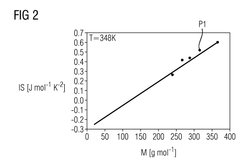
Fig. 2 shows a diagram to illustrate the correlation between
the molar mass of a fluid and of the inverse slope of
the saturated vapor line of the fluid;
Fig. 3 shows a temperature/entropy diagram for a fluid used in
a thermodynamic process;
Fig. 4 shows a diagram to illustrate the correlation between
the inverse slope of the saturated vapor line of a
fluid and the minimum required temperature increase;
and
Fig. 5 shows a diagram to illustrate the correlation between
the inverse slope of the saturated vapor line of a
fluid and of a minimum required enthalpy difference.
Fig. 1 shows an outline representation of a heat exchanger I
connected into a thermodynamic process, according to one
exemplary embodiment of the invention.
The thermodynamic process, which may for example be implemented
in a Reverse-Rankine process in a refrigerating machine or a
heat pump, comprises the steps carried out in succession in a
cycle process: evaporation of a liquid fluid, compression of
the fluid which is gaseous after the evaporation, condensation
of the compressed gaseous fluid, and expansion of the condensed
fluid which is liquid after the compression. The expanded fluid
which is in the liquid state is recompressed and the cycle
process begins again.
CA 02937029 2016-07-15
-2013P22191W0US
PCT/EP2015/050578
- 11 -
T1-ie respective steps are carried out by corresponding devices
.connected into the thermodynamic process. These include an
evaporation device 2 for evaporating the fluid, a compression
device 3 connected downstream thereof in the fluid flow for
compressing the fluid, a condensation device 4 connected
downstream thereof in the fluid flow, typically in the form of
a compressor, for condensing the fluid, and an expansion device
connected downstream thereof in the fluid flow, typically in
the form of an expansion valve, for expanding the fluid.
As can be seen, the heat exchanger 1 is connected between the
evaporation device 2 and the compression device 3. A heat
transfer surface, belonging to the high-temperature side of the
heat exchanger 1, is accordingly assigned to the fluid flow
between the evaporation device 2 and the compression device 3.
A heat transfer surface belonging to the low-temperature side
of the heat exchanger 1 is assigned to the fluid flow between
the condensation device 4 and the expansion device 5.
The fluid is, for example, a fluoroketone known by the brand
name NOVeCTM 649.
The heat exchanger 1 is produced by means of a special
production method. The method therefore relates in general to
the production of a heat exchanger 1 comprising at least one
heat transfer surface, which heat exchanger 1 is to be used in
a thermodynamic process in which a fluid that is condensed,
expanded, evaporated and compressed in a cycle process is used.
According to the method, besides other manufacturing technology
production steps for forming the heat exchanger 1, particular
surface sizing or dimensioning of the heat transfer surface on
the heat exchanger side is carried out. The surface sizing or
dimensioning of the heat transfer surface is carried out so
CA 02937029 2016-07-15
=2013P22191W0US
PCT/EP2015/050578
- 12 -
tl-iat it has a minimum surface area. The minimum surface area is
necessary at least for transfer of a minimum amount of heat to
a fluid to be used with the heat exchanger 1 to be produced in
the scope of a thermodynamic process. The minimum amount of
heat is the amount of heat which prevents condensation of the
fluid before, after and during the compression.
The heat transfer surface on the heat exchanger side is thus
sized with a view to particular process conditions or process
parameters of the thermodynamic process so that a sufficient
amount of heat can be transferred to the fluid via the heat
transfer surface which prevents condensation of the fluid
before, after and during the compression. In this way, it is
possible to prevent damage to the compression device 3 by so-
called liquid slugging.
In the scope of the method, the surface sizing of the heat
transfer surface on the heat exchanger side is carried out on
the basis of a correlation between the molar mass M of the
fluid and the minimum surface area.
Besides expediently predetermined process conditions or process
parameters of the thermodynamic process in which the heat
exchanger 1 to be produced is to be used, in order to carry out
the method according to the invention knowledge about the molar
mass M of the fluid to be used, or used, in the thermodynamic
process is thus necessary in particular.
In the scope of the correlation between the molar mass M of the
fluid and the minimum surface area of the heat transfer
surface, a correlation, i.e. establishment of a relationship,
between the molar mass M of the fluid with the inverse slope of
the saturated vapor line of the fluid is initially carried out.
CA 037029 2016--15
-2013P22191W0US
PCT/EP2015/050578
- 13 -
Th.e inverse slope of the saturated vapor line is respectively
.shortened to "IS" in the diagrams shown in Figs 2, 4 and 5.
Since the in principle fluid-specific inverse slope of the
saturated vapor line depends in particular on the temperature of
the fluid, the correlation between the molar mass M of the fluid
and the inverse slope of the saturated vapor line of the fluid is
expediently carried out for a given temperature of the fluid. The
temperature may, for example, be the evaporation temperature of
the fluid, i.e. the temperature which the fluid has after
evaporation, i.e. after leaving the evaporation device 2.
Fig. 2 shows a diagram to illustrate the correlation between
the molar mass M of a fluid (x axis) and the inverse slope of
the saturated vapor line of the fluid (y axis).
Various fluids, in particular fluoroketones, are plotted at a
temperature of 348 K. This temperature corresponds typically to
the evaporation temperature of a fluid in the scope of the
thermodynamic process. The evaporation temperature of the fluid
is, as mentioned, the temperature which the fluid has after
leaving the evaporation device 2.
With the aid of Fig. 2, it can be seen that there is an
(almost) linear relationship between the molar mass M and the
inverse slope of the saturated vapor line of corresponding
fluids.
The expediency of using the inverse slope of the saturated
vapor line of corresponding fluids due to the fact that many
fluids to be used, or used, in corresponding thermodynamic
processes have approximately vertical saturated vapor lines,
and therefore very high slopes. Use of the inverse slope of the
CA 02937029 2016-07-15
2013P22191W0US
PCT/EP2015/050578
- 14 -
saturated vapor line therefore allows better comparability of a
,plurality of fluids considered.
The progress of the method will be discussed below with the aid
of the perfluoromethylpentanone (brand name NOVeCTM 649) having
a molar mass M of about 316 g/mol. With the aid of Fig. 2, it
can be seen that the inverse slope of the saturated vapor line
of this fluid is 0.562 J mo1-1 K-2. The inverse slope of the
saturated vapor line of the fluid may therefore, in particular,
also be determined or ascertained graphically.
The inverse slope of the saturated vapor line is subsequently
correlated with a minimum required temperature increase of the
fluid starting from the assumed temperature, i.e. here starting
from 348 K. The minimum required temperature increase of the
fluid is the temperature increase which is at least required in
order to prevent condensation of the fluid before, after and
during the compression.
For more detailed explanation of the determination of the
minimum required temperature increase, reference is made to
Fig. 3, which shows a temperature/entropy diagram, or T/S
diagram for short, for a fluid used in a thermodynamic process.
The temperature T of the fluid is plotted on the y axis, and
the entropy S of the fluid is plotted on the x axis.
Essentially, with the aid of the T/S diagram shown in Fig. 3,
it is possible to see in particular a saturated vapor line 6 of
the fluid (cf. the right-hand branch of the graph), a boiling
line of the fluid (cf. the left-hand branch of the graph) and a
two-phase region 8 of the fluid. In the two-phase region 8, the
fluid is in two phases, i.e. a gaseous phase and a liquid
phase. In the area 9 lying to the right of the saturated vapor
line 6, the liquid is gaseous, and in the area 10 lying to the
left of the boiling line 7, the fluid is liquid.
CA 02937029 2016-07-15
2013P22191W0US
PCT/EP2015/050578
- 15
. As can be seen, the fluid has a strongly overhanging two-phase
region 8. This can be seen from the fact that the saturated
vapor line 6 of the fluid is strongly inclined in the direction
of increasing entropy.
The devices connected into the thermodynamic process, which
were described with reference to Fig. 1, are likewise entered
in Fig. 3. To the right of the reference line 2, the fluid has
accordingly left the evaporation device 3 (without taking into
account possible overheating in the evaporation device 2), to
the left of the reference line 3 the fluid has left the
compression device 3, etc. The compression of the fluid thus
takes place between the reference lines 3 and 4.
The minimum required temperature increase, which can be seen in
Fig. 3 by the double arrow P2, is abbreviated to "minAT" and is
given by the following formulae (1) - (5):
minAT = T3 - T2 (1)
with: T3 = temperature of the fluid when entering the
compression device 3; T2 = temperature of the fluid when
leaving the evaporation device 2.
The following applies in this case:
T3 = f(P2r h3) (2)
with: p2 = pressure of the fluid when leaving the evaporation
device 2; h3 = enthalpy of the fluid when entering the
compression device 3.
The following applies in this case:
CA 02937029 2016-07-15
2013P22191W0US
PCT/EP2015/050578
- 16 -
h3 = h4 - (h4 - h3s) / ns (3)
with: h4 - enthalpy of the fluid when entering the condensation
device 4; h3s = enthalpy of the fluid when entering the
compression device 3 in the case of an ideal efficiency of the
thermodynamic process of 1; ns = actual efficiency of the
thermodynamic process, an efficiency of about 0.8 typically
being assumed.
The following applies in this case:
h4 = f(T4 + 5K; p4) (4)
with: T4 = temperature of the fluid when leaving the
condensation device 4, 5 K being added to this temperature in
order to ensure that the fluid remains in the gaseous state; p4
= pressure of the fluid when leaving the condensation device 4.
The following further applies:
h3s = f (p2; s4) (5)
with: p2 = pressure of the fluid when leaving the evaporation
device 2; S4 = entropy of the fluid when entering the
condensation device 4.
Fig. 4 shows a diagram to illustrate the correlation between
the inverse slope of the saturated vapor line of a fluid (x
axis) and the minimum required temperature increase minnT (y
axis) which prevents condensation of the fluid in a
thermodynamic process before, during and after the compression.
With the aid of Fig. 4, it can be seen that there is an
(almost) linear relationship between the inverse slope of the
CA 02937029 2016-07-15
=2013P22191W0US
PCT/EP2015/050578
- 17 -
sturated vapor line and the minimum required temperature
,increase minAT of corresponding fluids.
The minimum required temperature increase minAT which can be or
is determined in this way is subsequently correlated with a
minimum required enthalpy difference minAh. The minimum
required enthalpy difference minAh represents the amount of
heat which must be transferred to the fluid in order to prevent
condensation of the fluid before, after and during the
compression. The minimum required enthalpy difference minAh is
therefore to be understood as the amount of heat which must be
transferred to the fluid via the heat transfer surface of the
heat exchanger in order to prevent condensation before, after
and during the compression.
Fig. 5 shows a diagram to illustrate the correlation between
the inverse slope of the saturated vapor line of a fluid (x
axis) and the minimum required enthalpy difference minAh (y
axis) which, as mentioned, represents the amount of heat which
must be transferred to the fluid in order to prevent
condensation of the fluid in a thermodynamic process before,
after and during the compression.
With the aid of Fig. 5, it can be seen that there is also an
(almost) linear relationship between the minimum required
enthalpy difference minAh and the inverse slope of the
saturated vapor line of the fluid, and therefore also the molar
mass M of the fluid.
The minimum required enthalpy difference minAh is subsequently
correlated with the minimum surface area of the heat transfer
surface. An area A is thus finally determined which corresponds
to the minimum surface area of the heat transfer surface of the
heat exchanger 1.
CA 02937029 2016-07-15
.2013P22191W0US
PCT/EP2015/050578
- 18 -
The correlation between the minimum required enthalpy
,difference minLh and the minimum surface area is carried out by
means of the following relationship:
nl-minAh = k = A = AT,
with =
fluid mass flow rate, minAh = enthalpy difference, k
= heat transfer coefficient, A = minimum surface area and AT =
temperature difference between a high-temperature side and a
low-temperature side of the heat transfer surface.
A particular heat transfer coefficient k and a particular
temperature difference AT are in this case assumed, in
particular as a function of the fluid or its chemical
composition, the material forming the heat exchanger 1 and
optionally further process conditions or process parameters of
the thermodynamic process.
In the scope of the correlation between the molar mass M of the
fluid and the minimum surface area of the heat transfer
surface, at least a particular temperature, in particular the
temperature of the fluid after the evaporation, and/or a
particular heat transfer coefficient k and/or a particular
temperature difference AT between a high-temperature side and a
low-temperature side of the heat transfer surface on the heat
exchanger side is thus used as a constraint.
In the scope of the method, particular process conditions or
process parameters of the thermodynamic process are therefore
defined as constraints. These also include in particular
predeterminable or predetermined operating parameters, i.e. in
particular powers or power consumptions, individual or multiple
devices connected into the thermodynamic process, which are
configured or designed for condensation, expansion, evaporation
CA 02937029 2016-07-15
2013P22191W0US
PCT/EP2015/050578
- 19
or compression of the fluid. For example, these include a
,condensation device connected 4 into the thermodynamic process
for condensing the fluid.
In respect of the minimum surface area, to be determined, of
the heat transfer surface, it applies qualitatively that this
is proportional to the amount of heat to be transferred to the
fluid via the heat transfer surface on the heat exchanger side.
The smaller the minimum required enthalpy difference minAh, the
smaller the minimum surface area of the heat transfer surface
on the heat exchanger side likewise is.
The correlation carried out in the scope of the invention
between the molar mass M of the fluid and the minimum surface
area of the heat transfer surface on the heat exchanger side is
typically carried out for a fluid, in particular an organic
fluid, having a molar mass of more than 150 g/mol. Such fluids
typically have an in particular strongly overhanging two-phase
region in their temperature/entropy diagram, or T/S diagram for
short.
Exemplary data of a minimum surface area determined in the
scope of the invention will be presented below. The fluid in
which the data are based is the aforementioned
perfluoromethylpentanone having a molar mass M of 316 g/mol.
A power Q of 1000 kW in the condensation device 4, an average
temperature difference AT of 10 K and a heat transfer
coefficient k of 200 W m-2 K-1 were assumed. In principle,
average temperature differences AT of between 5 and 30 K and a
heat transfer coefficient of between 50 and 1000 W m-2 K-1
should be assumed.
CA 02937029 2016-07-15
-2013P22191W0US
PCT/EP2015/050578
- 20 -
-
th ma,Q minAh Q. k AT A
[glmol) [kg/s] [kJ/ko] [kW] [kJ/kg] [kW] [kW/m2K) [K)
316 12,8 78,0 1000 25,9 332 0,2 ID 166
The method according to the invention therefore makes it
possible in a straightforward way to determine a heat transfer
surface on the heat exchanger side which is suitable for a
particular thermodynamic process. On the basis of the molar
mass M of the fluid to be used, or used, in the thermodynamic
process, it is possible to deduce the inverse slope of the
saturated vapor line of the fluid, the minimum required
temperature increase minAT, the minimum required enthalpy
difference minAh and furthermore a corresponding minimum
surface area of a heat transfer surface on the heat exchanger
side.
Although the invention has been illustrated and described in
detail with the preferred exemplary embodiment, the invention
is not restricted to the examples disclosed, and other variants
may be derived therefrom by the person skilled in the art
without departing from the protective scope of the invention.