Note: Descriptions are shown in the official language in which they were submitted.
CA 02937701 2016-07-22
WO 2015/128000 PCT/EP2014/054008
1
A razor handle comprising inserts within holes and razor
comprising such a razor handle
Field of the invention
The invention relates to razor handles and razors.
Background of the invention
More precisely, the invention relates to a razor
handle comprising an elongated body extending in a
longitudinal direction, said elongated body having an outer
surface and being provided with a first hole and a second
hole, said first and second holes opening on said outer
surface of the elongated body, said razor handle further
comprising a first insert and a second insert.
WO 2008147133 discloses an example of such a known
razor handle in which several inserts are provided on
different faces of the razor handle so as to provide a
proper weight to the handle assembly and prevent the
deformation of the elongated body.
However, these inserts consist in several different
pieces with complex shapes; therefore, a razor handle
provided with such inserts is difficult to assemble and to
manufacture. In addition, each of these inserts can
inadvertently be detached from the razor handle.
Summary of the invention
One objective of the present invention is to avoid
these drawbacks. More specifically, one problem of the
invention is to facilitate the manufacture of the razor
handle according to the invention.
Another problem is to improve the shaving experience
of the user while shaving.
Another problem is to avoid any inadvertent separation
of any of the inserts provided on razor handle according to
the invention.
CA 02937701 2016-07-22
WO 2015/128000 PCT/EP2014/054008
2
This problem is solved by the fact that, according to
the invention, said first and second inserts are
respectively partially encapsulated within said first and
second holes.
Thanks to the inserts, the razor handle can also have
a proper weight ensuring a precise and comfortable shaving
while providing an advantage for mass produced shavers.
In addition, since the inserts are encapsulated within
the elongated body, they cannot be detached from the first
and second holes; they especially cannot be detached from
the hole by a user. Also, such a razor handle has a better
hold and an improved resistance.
Thanks to the inserts, the razor handle can also have
a proper weight promoting a comfortable shaving. The
inserts allow the razor handle to have a good balance
regardless the shape of the handle.
Furthermore, such a razor handle according to the
present invention can be easily recycled by separating the
material of the inserts from the material of the elongated
body.
In advantageous embodiments of such a razor handle,
one and/or the other of the following features may be
incorporated:
¨ the razor handle extends between a front end and a
rear end, the rear end being opposite the front end,
the front end being provided with connecting means,
the first insert being located in the vicinity of the
front end and the first insert being immovable within
the first hole, the immovable first insert forming a
finger rest area;
Consequently, the user can position one or several of
his fingers on the first insert to grasp the handle.
CA 02937701 2016-07-22
WO 2015/128000 PCT/EP2014/054008
3
The razor handle thus provides a good shaving
experience with such a razor handle.
¨ the first insert is movable within the first hole ;
¨ the second insert is immovable within the second hole,
the immovable second insert forming a finger rest
area;
Consequently, the user can position one or several of
his fingers on the second insert to grasp the handle.
The razor handle thus provides a good shaving
experience with such a razor handle.
¨ the elongated body is a unitary element and comprises
a first material chosen among the plastics and the
rubbers;
¨ the first and second inserts are made in a rigid
material having a density that is different from the
density of the first material of the elongated body;
When the inserts comprise a material having a density
that is greater than the density of the first material
of the elongated body, the presence of the inserts
result in an increase of the weight of the razor
handle which improve the user's perception while
shaving. This increase of weight can be achieved by
reducing the use of first material and still
maintaining a good shaver handle design. The size and
shape of the razor handle may be then reduced but may
still keep an ergonomic shape.
¨ the first and second inserts comprises a material
chosen among the metals, the plastics and the rubbers;
¨ at least one of the first and second inserts is a
sphere; each of the first and second inserts can be a
sphere.
CA 02937701 2016-07-22
WO 2015/128000 PCT/EP2014/054008
4
¨ the first and second inserts each has a diameter which
is comprised between 10 mm and 20 mm;
¨ the elongated body has an upper face and a lower face,
the lower face being opposite the upper face, the
first and second holes being through-holes extending
between said upper and lower faces;
¨ the elongated body has an upper face and a lower face,
the lower face being opposite the upper face, at least
a part of the upper face and at least a part of the
lower face being covered with a second material so
that said parts respectively form at least an upper
gripping area and at least a lower gripping area;
¨ the elongated body has two lateral sides opposite to
each other and extending in the longitudinal direction
between the upper and lower faces, said lateral sides
comprising a plurality of smooth ribs made of the
second material, each of said smooth ribs connecting
together the upper gripping area and the lower
gripping area;
¨ the razor handle extends between a front end and a
rear end, the rear end being opposite the front end,
the front end being provided with connecting means for
connection to a shaving cartridge;
¨ the first insert is located in the vicinity of the
front end, whereas the second insert is located in the
vicinity of the rear end;
¨ the first insert is centered on a first point which is
located at a distance measured along the longitudinal
direction of about 30 mm from the front end;
¨ the second insert is centered on a second point which
is located at a distance measured along the
CA 02937701 2016-07-22
WO 2015/128000 PCT/EP2014/054008
longitudinal direction of about 20 mm from the rear
end;
¨ the distance between the first point and the second
point measured along the longitudinal direction is
5 comprised between 70 mm and 90 mm;
¨ each lateral sides comprises a plurality of spaced
protruding pins in the vicinity of the front end of
the razor handle;
¨ the first hole has an interior lateral wall, a
retaining ring protruding from said interior lateral
wall and surrounding circumferentially, at least
partially, the first insert for maintaining said first
insert within said first hole;
¨ the second hole is divided by an elongated bar
extending in the longitudinal direction, said
elongated bar comprising a portion that surrounds
circumferentially, at least partially, the second
insert for maintaining said second insert within said
second hole;
¨ the second hole comprises an interior lateral wall,
said second hole further comprising two projections
opposite each other, protruding from said interior
lateral wall, and having a shape which is partly
complementary to the shape of the second insert for
maintaining said second insert within said second
hole; and
¨ each of the first and second holes delimits an
interior space comprised inside the elongated body,
the first and second inserts having a size which is
respectively inferior to said interior spaces of said
first and second holes.
CA 02937701 2016-07-22
WO 2015/128000 PCT/EP2014/054008
6
The invention also concerns a razor comprising such a
razor handle and a shaving cartridge connected to the razor
handle.
The above and other objects and advantages of the
invention will become apparent from the detailed
description of one embodiment of the invention, considered
in conjunction with the accompanying drawings.
Brief description of the drawings
Figure 1 is a perspective view of a razor according to
the invention comprising a razor handle connected to a
shaving cartridge;
Figure 2 is a perspective view of the razor of figure
1, the shaving cartridge being released from the razor
handle;
Figures 3A and 3B are respectively an upper and a
lower view of the razor handle of figure 1;
Figure 4 is a side view of the razor handle of figure
1;
Figure 5 is a longitudinal section of the razor handle
shown in figure 3A along line V-V;
Figure 6 is a section of the razor handle shown in
figure 5 along line VI-VI;
Figure 7 is a section of the razor handle shown in
figure 3A along line VII-VII;
Figure 8 is a section of the razor handle shown in
figure 3A along line VIII-VIII;
Figure 9 is a partial upper view of the front end of
the razor handle of figure 3A.
Detailed description of the disclosure
In the various figures, the same references denote
identical or similar elements.
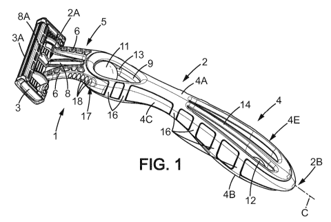
Figure 1 illustrates a wet shaving razor 1. The
present invention comprises a razor handle 2 and a shaving
CA 02937701 2016-07-22
WO 2015/128000 PCT/EP2014/054008
7
cartridge 3. The shaving cartridge 3 is preferably a
disposable shaving cartridge, comprising one or several
blades 3A, which can be connected to or release from the
razor handle 2 as shown respectively on figures 1 and 2.
The razor handle 2 has a generally curved shape
(viewed laterally) and extends in a longitudinal direction
C between a front end 2A and a rear end 2B, the rear end 2B
being opposite the front end 2A. The razor handle 2 has
also an elongated body 4 for hand grasping the razor handle
2. More precisely, the elongated body 4 extends
longitudinally from the rear end 2B to a location near the
front end 2A. The razor further comprises connecting means
5 in the continuation of the elongated body 4 up to the
front end 2A. In other words, the elongated body 4 extends
longitudinally from the rear end 2B to the beginning of the
connecting means 5. The shaving razor 1 extends
longitudinally from the rear end 2B to the free end of the
connecting means 5 (the free end being the one to be
connected to the shaving cartridge 3).
Referring to figure 3A and 3B, it can be seen that the
razor handle 2 can be symmetrical with respect of a median
plane P1 and has a length L in the longitudinal direction C
which is comprised between 100 mm and 150 mm, preferably
about 125 mm. The length L4 of the elongated body 4 is
about 100 mm to about 120 mm, whereas the length L5 of the
connecting means 5 is about 15 to 25 mm.
In a preferred embodiment, the length L of the razor
handle 2 is of about 126 mm. The length L5 of the
connecting means 5 is of about 17 mm. The length L4 of the
elongated body 4 is of about 108 mm.
The razor handle 2 may also define a variable height H
and a width W along the length L thereof. The height H of
the razor handle 2 may vary along the direction C but is
CA 02937701 2016-07-22
WO 2015/128000 PCT/EP2014/054008
8
preferably comprised between 15 mm and 25 mm, preferably
about 20 mm. As depicted in figure 4, the smallest height
H1 of the elongated body 4 is located about the center of
the razor handle 2.
It can be seen on the upper and lower views of the
razor handle 2 of figures 3A and 3B, that the razor handle
2 has also a first enlarged part Ep1 in the vicinity of the
front end 2A, having a width W1 which is maximized. The
elongated body also comprises a second enlarged part Ep2
located in the vicinity of the rear end 2B of the razor
handle 2 having a width W2 which is maximized. The first
and second enlarged parts Ep1, Ep2 are connected together
by a slim part Sp located about at the centre of the razor
handle 2. In particular, the slim part Sp has a width W3
which is minimized. The first enlarged part Ep1 extends
from this slim part Sp to the connecting means 5, whereas
the second enlarged part Ep2 extends from the rear end 2B
to this slim part Sp. The first and of the second enlarged
part Ep1, Ep2 have a length LEp1, LEp2 along the
longitudinal direction C which are respectively chosen such
that the connection between the first and second enlarged
parts Ep1, Ep2 with the slim part Sp have a smooth
curvature.
In a preferred embodiment, the length LEp1 of the
first enlarged part Ep1 is of about 25 mm. The length LEp2
of the second enlarged part Ep2 is of about 50 mm. The
length LSp of the slim part Sp is of about 25 mm.
The connecting means 5 are integral with the elongated
body 4 and comprises two flexible arms 6 extending from the
elongated body 4 and protruding toward a free end 6B at the
front end 2A of the razor handle 2. In other words, the
flexible arms 6 and the elongated body 4 are unitary.
CA 02937701 2016-07-22
WO 2015/128000 PCT/EP2014/054008
9
As depicted on figure 9, the two arms 6 may be
disposed in a V shape, diverging from the longitudinal
direction C of the razor handle 2 each provided, at the
free end 6B, with a bearing structure 7 for connection to
the shaving cartridge 3. In the disclosed embodiment, the
shaving cartridge 3 is of the pivotal type, the bearing
structures 7 allowing the pivoting of the shaving cartridge
3 when connected to the razor handle 2, whereas a
longitudinal flexible tongue 8, extending between the arms
6 and cooperating with a groove 8A formed on the shaving
cartridge 3, provides a spring force which biases the
shaving cartridge 3 towards a rest position as illustrated
in figure 1. However, the shaving cartridge 3 may also be
fixed relatively to the razor handle 2.
Each arm 6 further has on its upper face a plurality
of small cavities 21. Such a structure provides enough
structural strength to the connecting means 5 for the
purposes of human shaving, while saving weight and costs on
this part of the razor handle 2.
The elongated body 4 has an outer surface 4E, and more
precisely an upper face 4A and a lower face 4B as depicted
on figures 4A and 4B, the lower face 4B being opposite the
upper face 4A. The elongated body 4 further has two lateral
sides 4C, 4D comprised between the upper and lower faces
4A, 4B, opposite each other and also extending in the
longitudinal direction C.
The elongated body 4 and the connecting means 5 form a
unitary element moulded out of a first material. The first
material may be any moldable material. Preferably, the
first material ischosen among the plastics and the rubbers.
For instance, the elongated body 4 and the connecting means
5 can be moulded in a thermoplastic material, for instance
CA 02937701 2016-07-22
WO 2015/128000 PCT/EP2014/054008
in acrylonitrile butadiene styrene (ABS) or in
polypropylene (PP).
The elongated body 4 further includes a first hole 9
and a second hole 10. The first and second holes 9, 10 are
5 respectively located in the first enlarged part Ep1 and in
the second enlarged part Ep2 of the razor handle 2.
The first and second holes 9, 10 are preferably
through-holes that extend between the upper face 4A and the
lower face 4B of the elongate body 4. However, the first
10 and second holes 9, 10 may also be blind holes that open on
the outer surface 4E of the elongated body 4, and in
particular on the upper face 4A or on the lower face 4B.
As shown in figures 7 and 8, each of the first and
second holes 9, 10 has respectively an interior side wall
9A, 10A, each of which delimiting an interior space 9B, 10B
comprised inside the elongated body 4 between the upper and
the lower faces 4A, 4B. More particularly, the interior
side walls 9A, 10A of each of the first and second holes 9,
10 comprise a semi-circular portion 9C, 10C and converge in
a V-shape from these semi-circular portion 9C, 10C in the
longitudinal direction C towards the slim part Sp in the
centre of the razor handle 2. Also, both of the first and
second holes 9, 10 preferably have drop-shapes respectively
oriented in opposite direction when seen from an upper or a
lower view as illustrated in figure 3A and 3B. In other
words, viewed from the top or lower side, the two holes
connected via the slim part Sp, have a general shape
forming a kind of eight.
The length L9 of the first hole 9 along the
longitudinal direction is comprised between 10 mm and
30 mm, preferably about 20 mm. The length L10 of the second
hole 10 along the longitudinal direction is comprised
between 30 mm and 50 mm, preferably about 40 mm. Also, as
CA 02937701 2016-07-22
WO 2015/128000 PCT/EP2014/054008
11
illustrated in figure 3B, the first enlarged part Ep1
extends from the connecting means 5 to the end of the first
hole 9 located towards the centre of the razor handle 2.
The slim part Sp extends from this end of the first hole 9
located towards the centre of the razor handle 2 to the end
of the second hole 10 also located towards the centre of
the razor handle 2. The second enlarged part Ep2 extends
from the end of the second hole 10 located towards the
centre of the razor handle 2 to the rear end 2B.
The razor handle 2 further comprises a first insert 11
and a second insert 12 located respectively within the
interior space 9B, 10B of each first and second holes 9,
10. More precisely, the first and second inserts 11, 12 are
respectively partially encapsulated within the first and
second holes 9, 10 as illustrated in figure 5. Besides, the
surface of the first and second inserts 11, 12 can be
directly or indirectly, as detailed hereafter, touchable
with a finger of a user. Besides, the surface of each of
the first and second inserts 11, 12 can form finger rest
areas on the upper face 4A and/or on the lower face 4B of
the elongated body 4. Preferably, less than 75%, and
preferably less than 50 % of the surfaces of the first and
second inserts 11, 12 are encapsulated within the first and
second holes 9, 10. In other words, the surface of the
first and second inserts 11, 12 which is encapsulated
cannot be directly touchable by the user as it is
surrounded with the first material of the elongated body 4.
In this manner, when a user wants to shave, he may
position his fingers on the location of the first and
second holes 9, 10, and preferably on the surfaces of the
first and second inserts 11, 12 which are not encapsulated.
Preferably, the first and second inserts 11, 12 enhance
hand grasping in certain shaving positions, such as in a
CA 02937701 2016-07-22
WO 2015/128000 PCT/EP2014/054008
12
position where the razor handle 2 is held between the index
and the thumb, the thumb resting on the first insert 11 on
the upper face 4A whereas the index rests on the first
insert 11 on the lower face 4B of the razor handle 2. In
another shaving position, the thumb and the index of the
user can also rest on the second insert 12. As it will be
detailed below, the second insert 12 may not be directly
touchable with a finger of a user on the upper face 4A as a
rib 14 may cover partially the second insert 12. The user
may therefore position his finger(s) on the rib 14 on the
upper face 4A of the elongated body 4 when shaving.
Although covered by said rib 14, the second insert 12
however forms a finger rest area since it supports the rib
14. In other means, it is like the second insert 12 would
be covered at least partially with another material (i.e.
the material of the rib 14).
The first and second inserts 11, 12 are preferably
made in a material chosen among the metals, the plastics
and the rubbers. In particular, the first insert 11 and/or
the second insert 12 is preferably made in a rigid material
having a density that is significantly different from the
density of the first material of the elongated body 4.
For instance, the density of the first and second
inserts 11, 12 may be greater than the density of the first
material of the elongated body 4. The first and second
inserts 11, 12 thus contribute to raise weight of the razor
handle 2 without significantly increasing the volume of the
handle 2. As a consequence, the razor handle 2 can be heavy
enough to provide a good shaving and to make sure that a
good contact is provided between the blades 3A of the
shaving cartridge 3 and the skin of the user to be shaved.
Preferably, each of the first and second inserts 11, 12 is
CA 02937701 2016-07-22
WO 2015/128000 PCT/EP2014/054008
13
only made of metal and does not comprise any other
material.
The material chosen for the first insert 11 and/or the
second insert 12 may also have an impact on the sensing
experience of the user when he positions his fingers on the
first and second inserts 11, 12. As an example, an insert
made of metal provides a pin-point contact with the fingers
of the user, thus allowing the communication of all
transmitted vibrations from shaving. To the contrary, an
insert made of rubber, such as thermoplastics, absorbs most
of the vibrations from shaving and does not transmit them
to the fingers of the user.
As an alternative, the first and second inserts 11, 12
may not be both necessarily in the same material. For
instance, the first insert 11 provided within the first
hole 9 may be made of metal and the second insert 12
provided within the second hole 10 may be made of rubber or
vice versa.
Besides, each of the first and second inserts 11, 12
can also be made with several materials. In particular, the
first and second inserts 11, 12 can be covered with a layer
of another material having a smooth surface. As an example,
the first and second inserts 11, 12 may be made of metal
and covered by a layer of rubber. In this embodiment, the
layer can have a surface finish comprised between 0.5 pm
and 1.6 pm (roughness Ra).
The first and second inserts 11, 12 may also have an
irregular surface, for instance with craters or bumps due
to a knurled pattern or a divot pattern. As a matter of
fact, the type of surface of the first and second inserts
11, 12 affect the tactile sensing of the user when he
positions his fingers on the first and second inserts 11,
12.
CA 02937701 2016-07-22
WO 2015/128000 PCT/EP2014/054008
14
As another alternative, the first insert 11 and/or the
second insert 12 may be a sphere of which one hemisphere is
made of rubber and the other hemisphere is made of plastic.
The first and second inserts 11, 12 may thus serve a double
purpose by providing different types of finger rest areas.
Due to the first and second inserts 11, 12, the
elongated body 4 can therefore be in a material which is
lighter and cheaper when compared to the material used in
known razor handles. Nevertheless, despite the lightness of
the first material, the razor handle 2 still has a good
quality appearance and an optimized weight thanks to the
first and second inserts 11, 12. Besides, the weight of the
razor handle 2 is chosen to be localized in the front end
2A and the rear end 2B of the razor handle 2, thus ensuring
a good balance of the razor handle 2.
The first insert 11 and/or the second insert 12 may
have a spherical shape. The first inserts 11 and/or the
second insert 12 may have an ovoid shape. More generally,
the inserts may have any other shape such as a
parallelipipedic, cubical or cylindrical shape. Besides,
the first and second inserts 11, 12 may have the same shape
or may have a different one. Similarly, first and second
inserts 11, 12 may have the same dimensions or may have
different ones. Besides, the first and second inserts 11,
12 may comprise the same material(s) or may comprise a
different one(s).
Preferably, the inclusion of the first and second
inserts 11, 12 does not lead to an excessive deformation of
the shape of the elongated body 4. Besides, the shape of
the elongated 4 preferably remains similar to the shape of
an elongated body that would not include any insert. As
depicted on the figures 1-3 and 5-8, each of the first and
second inserts 11, 12 is preferably a single sphere.
CA 02937701 2016-07-22
WO 2015/128000 PCT/EP2014/054008
However, each of the first and second inserts 11, 12 may
not be complete spheres and may only comprise a partial
curved surface, especially a partial spherical surface
which serves as a finger rest area.
5 Besides, the first and second inserts 11, 12 have a
size which is respectively inferior to the interior spaces
9B, 10B of each first and second hole 9, 10. Also, as
illustrated on figures 4A and 3B, the length of the first
and second holes L9, L10 in the longitudinal direction C is
10 greater than the longitudinal size of the first and second
inserts 11, 12. More particularly, in the particular
embodiment in which the inserts are spheres as depicted on
the figures, such spheres have preferably a diameter D
which is comprised between 10 mm and 20 mm, preferably
15 inferior to 15 mm, and more preferably of about 12 mm.
In one embodiment, the first and second inserts 11, 12
are preferably maintained, advantageously secured,
respectively within the first and second holes 9, 10 and
can therefore not be detached from the first and second
holes 9, 10 by a user. Besides, the first and second
inserts 11, 12 cannot move in any manner in the first and
second holes 9, 10. As a consequence, the first and second
inserts 11, 12 are not movable (i.e. immovable or
motionless) respectively relative to the first and second
holes 9, 10. The non-movable first and second inserts 11,
12 thus form finger rest areas. More precisely, the first
and second inserts 11 and 12 cannot slide in their
corresponding first and second holes 9, 10.
More particularly, as depicted in figure 7, a
retaining ring 13 protrudes from the interior side wall 9A
of the first hole 9 in a plane P2 perpendicular to the
symmetry plane P1 of razor handle 2 and surrounds
CA 02937701 2016-07-22
WO 2015/128000 PCT/EP2014/054008
16
circumferentially partially the first insert 11 for
maintaining said first insert 11 within said first hole 9.
However, in another embodiment, the first insert 11
and/or the second insert 12 may be a sphere that can rotate
on itself about its own axis in all directions. Also, a gap
may be provided between the first insert 11 and the
retaining ring 13 in order to facilitate the rotation of
the first insert 11 when it is a sphere. The gap may be
comprised between 0.005 pm and 0.025 pm depending on the
chosen rotational freedom of the first insert 11. A smaller
gap prevents the first insert 11 from rotating easily
whereas a bigger gap facilitates the rotation. The surface
finish of the first insert 11 and/or the second insert 12
and/or of the first hole 9 and/or the second hole 10 is
adapted to allow this movability, especially the rotation.
Thus, in that case, one among the first insert 11
and/or the second insert can be immovable.
In another embodiment, both the first insert 11 and
the second insert 12 are movable. The first insert 11 and
the second insert 12 can for instance be spheres that are
movable, especially in sliding around their own axis within
their corresponding first and second holes 9, 10.
In the case where the first and/or second inserts 11,
12 comprise two hemispheres made of different materials and
thus having different density, the user can switch between
the two hemispheres as needed by rotating the first and
second inserts 11, 12.
A user that may position one of his fingers on such a
movable first insert 11 and/or second insert 12 will find
difficult to shave as his finger(s) will constantly slip on
the first insert 11 and/or the second insert 12. Shaving
will therefore be imprecise and uncomfortable.
CA 02937701 2016-07-22
WO 2015/128000 PCT/EP2014/054008
17
As a consequence, when the first or second insert 11,
12 is movable respectively relative to corresponding first
or second holes 9, 10, it cannot form fingers rest areas.
More precisely, when the first insert 11 is movable, it
cannot be a finger rest area.
As illustrated in figure 8, the second hole 10 is
divided in two parts by an elongated bar 14 extending in
the longitudinal direction C and within the second hole 10
in the plane Pl. The elongated bar 14 comprises a portion
14A that surrounds circumferentially partially the second
insert 12 for maintaining said second insert 12 within said
second hole 10. The interior side wall 10A of the second
hole 10 also comprises two small projections 15A, 15B
opposite each other, protruding from the interior side wall
10A, and having a shape which is partly complementary to
the shape of the second insert 12 for maintaining said
second insert 12 within said second hole 10. However, as
described above regarding the first insert 11, a gap may
also be provided between the second insert 12 and the
portion 14A in order to facilitate the rotation of the
second insert 12 when this second insert 12 is a sphere.
By being respectively maintained in the first and
second holes 9, 10, the first and second inserts 11, 12 are
respectively located in the front end 2A and the rear end
2B of the razor handle 2. Preferably, the first insert 11
is centered on a first point 11A which is located at a
distance L11 measured along the longitudinal direction (C)
of about 25 mm from the front end 2A. The second insert 12
is located in the vicinity of the rear end 1B. Preferably,
the second insert 12 is centered on a second point 12A
which is located at a distance L12 measured along the
longitudinal direction C of about 25 mm from the rear end
2B.
CA 02937701 2016-07-22
WO 2015/128000 PCT/EP2014/054008
18
As illustrated on figure 5, in the particular
embodiment in which the first and second inserts 11, 12 are
spheres, the first point 11A and the second point 12A
respectively correspond to the centre of said first and
second inserts 11, 12.
The distance L11-12 between the first point 11A and
the second point 12A measured along the longitudinal
direction (C) is preferably comprised between 60 mm and
100 mm, preferably of about 78 mm. However, this distance
L11-12 may vary depending on the length L4 of the elongated
body 4 as well as on the weight balance to be preferred due
to the first and second inserts 11, 12.
In particular, known razors without inserts usually
have a center of balance that is located in the center of
the razor handle, or slightly towards the front end toward
the razor handle. To this end, the rear part of the razor
handle cannot be much larger than its front part, and vice
versa, in order to achieve this center of balance. In the
present invention, by adding the first and second inserts
11, 12 at precise locations from the front end 2A and the
rear end 2B of the razor handle 2, it is possible to
control the location of this center of balance regardless
the shape of the razor handle 2. For instance, the center
of balance may be positioned at the center of the razor
handle 2 in the longitudinal direction (C) even though the
second enlarged part Ep2 is significantly larger than the
first enlarged part Ep1.
The elongated body 4 may comprise several different
materials. For instance, the elongated body 4 may also
comprise a layer of a second material different from the
first material, preferably chosen among the plastics and
the rubbers. The first material provides structural
strength to the razor handle 2, while the second material
CA 02937701 2016-07-22
WO 2015/128000 PCT/EP2014/054008
19
provides the softness required for comfortable hand
grasping and firm finger gripping in any shaving position.
As depicted in figures 3A and 3B, at least a part 19
of the upper face 4A and at least a part 20 of the lower
face 4B, and preferably the majority of these faces 4A, 4B,
can be covered with the second material so that said parts
19, 20 respectively form an upper gripping area and a lower
gripping area. As depicted in figure 7, the second material
may also overflow, at least partially, on the interior side
wall 9B of the first hole 9 without covering the retaining
ring 13 which maintains the first insert 11.
The lateral sides 4C, 4D of the elongated body 4
further comprises a plurality of smooth ribs 16 made of the
second material. As shown in figure 4, each lateral side
4C, 4D of the elongated body 4 comprises preferably a
plurality of ribs 16 connecting together the upper and
lower gripping areas 19, 20. In the particular embodiment
shown in figure 4, each of the lateral sides 4C, 4D of the
first enlarged part Ep1 comprises two ribs 16 and the
lateral sides 4C, 4D of the second enlarged part Ep2
comprises four ribs 16.
As depicted on figures 1-4 and 9, each lateral side
3C, 4D may also comprise a side gripping area 17 comprising
a plurality of spaced protruding pins 18 integral with the
connecting means 5 and located in the vicinity of the front
end 2A of the razor handle 2 at the junction of the
connecting means 5 with the elongated body 4. The side
gripping areas 17 enhance finger gripping of the razor
handle 2, especially in a shaving position where the thumb
and the index finger are positioned very close to the front
end 2A, and preferably to the arms 6 for satisfying the
need of precise shaving.
CA 02937701 2016-07-22
WO 2015/128000 PCT/EP2014/054008
According to the invention, the insert (first
and/or second) can be movable or immovable in its
corresponding hole; besides, the insert (first and/or
second) can be a sphere or of any other shape allowing the
5 movability of the insert. The material and/or the surface
finish of the insert (first and/or second) and/or of the
hole (first and/or second) is adapted to allow this
movability, especially by rotation. Besides, the insert
(first and/or second) even when movable is not detachable
10 from the handle when inserted in the corresponding hole.