Note: Descriptions are shown in the official language in which they were submitted.
CA 02937765 2016-07-22
WO 2015/089272 PCT/US2014/069718
1
POROUS GRAPHENE NETWORK ELECTRODES AND
AN ALL-CARBON LITHIUM ION BATTERY CONTAINING THE SAME
CROSS-REFERENCE TO RELATED APPLICATIONS
This application claims priority to U.S. Provisional Application No.
61/915,030
filed on December 12, 2013, the contents of which are incorporated herein in
its
entirety.
FIELD OF THE INVENTION
The invention relates to electrode materials containing graphene and methods
of manufacturing the materials that may be incorporated into commercial
applications, such as rechargeable batteries.
BACKGROUND OF THE INVENTION
The global market for lithium ion batteries was $11.7 billion in 2012 and is
expected to double by 2016 to an estimated $22.5 billion. While lithium-ion
batteries
are already ubiquitous in consumer electronics, new and emerging markets,
specifically those of electric vehicles, have also found an ideal solution in
next
generation lithium ion batteries as the primary energy storage mechanism. The
success of lithium ion batteries has greatly been attributed to its high
energy density
of ¨200 Wh/kg, far surpassing other energy storage devices including nickel
cadmium, nickel metal hydride, and lead acid batteries. The term "energy
density"
translates to longer operational times on a single charge and hence on this
account,
lithium ion batteries have been considered ideal for consumer electronics, as
well as
electric vehicles and grid storage.
However, lithium ion batteries exhibit a significant limitation in terms of
their
power density. In general, lithium ion batteries deliver power densities of
¨100
W/kg, which is two to three orders of magnitude lower than super-capacitors
and
three orders of magnitude lower than combustion engines. Since power density
CA 02937765 2016-07-22
WO 2015/089272 PCT/US2014/069718
2
translates to how quickly a battery can deliver power to a device, this
limitation
significantly affects the successful and large-scale incorporation of lithium
ion
batteries in electric vehicles. In fact, electric vehicles are often equipped
with
additional super-capacitors that provide the necessary power boost during
events
such as acceleration and regenerative braking. Such a battery/super-capacitor
system not only makes the design of the energy storage system complicated, but
also
contributes towards increased cost and maintenance. Moreover, in order to make
electric vehicles a feasible alternative, it is also of utmost necessity that
the energy
density of such batteries be increased further to provide sufficient mileage
on a single
charge, capable of comparison with conventional internal combustion engines.
In
general, as the demand for an efficient solution for the impending energy
crisis
continues to rise, it is incumbent upon the battery community to identify and
develop
a superior lithium-ion battery that can boost its adoption across various
sectors
including automotive and grid storage, as well as portable electronics.
SUMMARY OF THE INVENTION
According to a first embodiment of the present invention, a system for the
production of graphene oxide sheets is provided. The system comprises a
counter
electrode and a working electrode immersed in a bath, the bath containing a
dispersion of graphene oxide, a substrate applied to a surface of the counter
electrode, and a source of electricity configured to apply a current between
the
counter electrode and the working electrode capable of electrolytically
depositing the
graphene oxide in the bath onto the substrate.
In another embodiment of a system according to the present invention, the
system comprises a heated substrate, a dispersion of graphene oxide, and a
spray
nozzle configured to spray the dispersion of graphene oxide onto the heated
substrate.
CA 02937765 2016-07-22
WO 2015/089272 PCT/US2014/069718
3
According to another embodiment of the present invention, a lithiated porous
graphene network (Li PGN) cathode is provided and a method for making the
same.
The Li PGN cathode comprises a sheet of graphene, the graphene being
intercalated
with lithium metal. The method comprises thermally reducing a sheet of
graphene
oxide to produce a sheet of graphene and exposing the sheet of graphene to
lithium
or a lithium-containing compound to produce the Li PGN cathode. The Li PGN
cathode
may be combined with a PGN anode and an electrolyte to provide an "all-carbon"
battery that may be useful in various applications, like automotive
applications, for
example.
BRIEF DESCRIPTION OF THE FIGURES
Figure 1(A) is the capacity and coulombic efficiency vs. cycle index of an
anode
according to an embodiment of the present invention compared to the
theoretical and
practical capacity of a graphitic anode.
Figure 1(B) is the voltage profile of an anode according to an embodiment of
the present invention.
Figure 1(C) is an X-ray Photoelectron Spectroscopy (XPS) Li is scan of a
lithiated and delithiated electrode according to an embodiment of the present
invention and a bare lithium metal foil.
Figure 1(D) is an X-Ray Diffraction (XRD) profile of a lithiated electrode
according to an embodiment of the present invention.
Figure 2(A) is a model of a graphene lattice having 2 5 /o divacancy defects.
Figure 2(B) is a model of the lattice of Figure 2(A) including lithium metal.
Figure 2(C) is the calculated capacity (mAh/g) vs. lithiation potential (eV)
for
graphene at various divacancy defect densities.
CA 02937765 2016-07-22
WO 2015/089272 PCT/US2014/069718
4
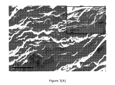
Figure 3(A) is a cross-section Scanning Electron Microscopy (SEM) image of a
completely lithiated electrode according to an embodiment of the present
invention.
Figure 3(B) is a cross-section SEM image of a completely delithiated electrode
according to an embodiment of the present invention.
Figure 4(A) is a schematic of a full cell configuration including a
lithium/PGN
composite as cathode and a PGN as an anode according to an embodiment of the
invention.
Figure 4(B) is the capacity and coulombic efficiency vs. cycle index of
lithium/PGN cathodes at a charge/discharge rate of ,s,1C (current density of
¨0.3 A/g)
compared to various cathode materials measured at comparable current
densities.
Figure 4(C) is a voltage profile of a cathodic half-cell according to an
embodiment of the present invention.
Figure 4(D) is a photograph of an LED device powered by a macroscopic pouch
cell containing a PGN anode and Li-PGN cathode according to an embodiment of
the
invention.
Figure 5 is an SEM image of graphene oxide directly deposited onto conductive
carbon felt substrate using an electro-deposition technique according to the
present
invention.
Figure 6 is a schematic of a roll-to-roll electro-deposition assembly
according
to another embodiment of the present invention.
DETAILED DESCRIPTION OF THE INVENTION
According to one embodiment of the present invention, an electro-deposition
technique is provided for the manufacture of graphene oxide on an industrial
(extremely large-scale) level. The deposition technique and parameters may
reduce
synthesis time and increase through-put, thereby ensuring economical
manufacturing
of graphene and/or graphene oxide free-standing sheets. The process may in
further
CA 02937765 2016-07-22
WO 2015/089272 PCT/US2014/069718
include the deposition of graphene oxide and/or graphene directly onto pre-
determined substrates, which is useful for coating graphene and/or graphene
oxide
for a variety of applications, such as coating metals to prevent corrosion or
to provide
an insulating (graphene oxide) layer on conductive substrates, for example.
Thus,
5 electro-deposition methods according to the present invention may be
applied where
either (a) a graphene oxide passivating and/or insulating coating is required
on a
conductive substrate or (b) a conductive graphene sheet is required that
increases the
surface area and/or enhances electron transport kinetics and/or improves the
electrochemical reaction efficiencies within a system. The process may further
include
a reduction method to yield graphene free-standing sheets from as-deposited
graphene oxide sheets. The sheets may be used as starting materials for
products,
such as electrodes, for example. Finally, a roll-to-roll automation strategy
may be
implemented with the electro-deposition process for the synthesis of graphene
oxide
and/or graphene sheets.
Conventionally graphene is synthesized via vacuum filtration of graphene oxide
followed by reduction of the graphene oxide. In this process a solution of
graphene
oxide is dispersed in DI water and filtered through a porous Anodisc membrane.
However, as the graphene oxide sheets continue to get deposited on the Anodisc
membrane, the pressure drop across the filter increases resulting in a rapid
decrease
in the rate of deposition. Generally, vacuum filtration is a process that is
extremely
slow (taking up to 3-4 days to create a free-standing sheet roughly 17 cm2 in
area
and 20 pm thick) and non-scalable (the mass loading is generally between 0.01-
0.1
mg/cm2). In order to provide a commercially feasible method of manufacturing
graphene oxide, it is therefore essential to ensure a scalable synthesis and
reduction
process that can provide large area graphene sheets (> 10 cm2) that are
significantly
thicker (> 20 microns) and with a higher mass loading (> 0.1 mg/cm2) at higher
CA 02937765 2016-07-22
WO 2015/089272 PCT/US2014/069718
6
rates of production to meet the potential demands for the material.
According to a first system according to the present invention, graphene oxide
sheets may be synthesized by an electro-deposition process whereby an current
is
applied between a counter electrode made from stainless steel or titanium
mesh, for
example, and a working electrode comprising a flattened sheet, preferably made
from
aluminum. The counter electrode and the working electrode are preferably
immersed
in an aqueous dispersion bath comprising the graphene oxide. Preferably, the
working electrode is formed into a sheet with minimum perturbations to prevent
the
formation of air pockets. The system may further comprise a mildly hydrophilic
porous polymer membrane, such as polypropylene, cellulose ester, or PTFE,
applied to
an external surface of the aluminum sheet. Alternatively, the working
electrode may
be comprised only of a conductive substrate such as stainless steel, copper,
aluminum
and carbon. A voltage applied between the electrodes may cause the graphene
oxide
to flow towards the working electrode where the graphene oxide gets trapped at
the
polymer membrane. The voltage may be at least 2 V, preferably about 2 to 10
V..
Increasing the voltage will increase the rate of deposition, thereby
decreasing
processing time; however, increased voltage will consume more energy adding to
the
operating cost of the system. The incremental increase in deposition rate may
not
justify the energy cost. Once the required deposition is complete, the working
electrode and polymer membrane configuration may be removed from the bath and
dried, preferably at room temperature. Drying time may last approximately 6
hours.
The drying process may be further accelerated through carrying out the step in
a
vacuum furnace maintained between 30-70 C, allowing the drying process to be
completed within 1-2 hours. At the end of the drying stage, the graphene oxide
sheet
may be simply peeled off the polymer membrane to obtain a free-standing
graphene
oxide electrode pre-cursor.
CA 02937765 2016-07-22
WO 2015/089272 PCT/US2014/069718
7
An SEM image of a graphene oxide sheet made by an electro-deposition
process according to the present invention is provided as Figure 5. The
process, as
described above was employed, except that in place of a mildly hydrophilic
polymer
substrate, graphene oxide in this case was deposited directly on carbon felt,
which
acted as the working electrode assembly.
In a second embodiment of a system according to the present invention, a roll-
to-roll electro-deposition strategy has been developed. Referring to the
schematic of
Figure 6, this embodiment may include a carrier substrate in the form of a
polymer
membrane at the beginning of the deposition line that travels through a
deposition
bath comprising the graphene oxide aqueous dispersion. The membrane substrate
is
slidably applied to the surface of a working electrode and may be advanced and
held
in place via a plurality of rollers. As the polymer membrane passes through
the bath,
the electro-deposition process, similar to the first embodiment, may be
carried out,
and graphene oxide may be deposited directly onto the polymer membrane. Upon
obtaining a pre-determined target thickness of graphene oxide coverage, the
membrane is then advanced out of the bath and may be passed through a pair of
pinch rollers that squeeze out excess water and permit faster drying of the
sheets.
The membrane is then advanced to an ambient drying zone in which exposure to
ambient air dries the deposited graphene oxide web. Alternatively, heated air
may be
provided to the drying zone by, for example, delivering air through a heating
means,
such as a hot plate or other heat exchanger. The elevated temperature of the
drying
zone is preferably maintained at 40-50 C.. Once dried, the graphene oxide web
may
optionally pass through another set of pinch rollers to remove remaining
traces of
water after which the polymer membrane and graphene oxide sheets may be
separated. Upon separation, the polymer membrane may be wound on a membrane
CA 02937765 2016-07-22
WO 2015/089272 PCT/US2014/069718
8
take-up reel while the graphene oxide web is directed to a reduction stage. At
the
reduction stage, the graphene oxide is reduced using thermal or photo-thermal
reduction in more detail below to convert the web to graphene. The resulting
graphene web may be finally directed to a graphene take-up reel. All or a
portion of
the roll-to-roll electro-deposition process may be automated to provide a
continuous
cost-effective process by reducing man-power and increasing through-put.
In a third embodiment of a system according to the present invention, the
graphene oxide pre-cursor may be synthesized by ultrasonic spray deposition. A
substrate similar to the mildly hydrophilic polymer membrane as discussed
above, for
example, may be applied to a porous plate. Means for holding the substrate in
place
may preferably include vacuum suction to prevent the formation of air pockets
between the plate and the polymer membrane. The substrate may be maintained at
an elevated temperature of 20 to 100 C, preferably about 50 to 70 C, to enable
rapid
drying. Graphene oxide dispersed in a carrier fluid, such as ethanol or water,
may be
sprayed directly onto the substrate using, for example, a 120 kHz impact
nozzle. The
substrate maintains a relatively fixed position while the nozzle is preferably
programmed to cover the entire substrate area for uniform deposition. The rate
of
production would therefore be easily scalable and controlled by the area of
the
substrate, the thickness of the each layer applied per pass, the volumetric
flow rate of
the spray nozzle, and the necessary dwell time between passes to allow each
sprayed
layer to dry based on the volatility of the carrier fluid and drying
temperature. In a
preferred embodiment of the spray deposition technique, a scalable graphene
oxide
may be synthesized having a 20 to 50 micron cross-sectional thickness. The
resulting
material may be used as an electrode pre-cursor that is subsequently reduced
to
graphene. Multiple passes of the nozzle (coating cycle) may be carried out to
achieve
the desired thickness. A single coating cycle preferably lasts about 60-120
seconds.
CA 02937765 2016-07-22
WO 2015/089272 PCT/US2014/069718
9
At the end of every single coating cycle, a 5-10 seconds dwell time may be
incorporated to facilitate drying of the as-deposited graphene oxide.
According to another embodiment of the present invention, a type of super-
capacitor battery is disclosed, i.e. a set of materials that can deliver
higher power
densities while maintaining excellent energy densities that may be especially
relevant
for hybrid electric vehicles for which large battery packs heretofore have
been unable
to provide enough power density for acceleration. Other embodiments of the
present
invention provide a super-capacitor battery that may be integrated with
regenerative
braking systems, which involves recharging the batteries at a very high rate,
and may
provide a potential comprehensive solution for the transportation industry.
Super-
capacitory batteries according to some embodiments of the present invention
may
include convective heat-reduced graphene-based anodes and convective heat-
reduced
pre-lithiated graphene cathodes.
Conventionally, the anode in a lithium ion battery is graphite while the
cathode
comprises a lithium-based composite such as lithium cobalt oxide or lithium
iron
phosphate. In contrast, electrodes according to various embodiments of the
present
invention may comprise graphene as the anode and a lithium-graphene composite
as
the cathode. According to other embodiments of the present invention, a method
of
manufacturing anodes and cathodes may include an electro-deposition based
approach to synthesize the electrodes quickly, economically, and in large
quantities.
The combination of a rapid, yet simple synthesis technique and the unique
material
properties offered by both the anodes and cathodes according to the
embodiments of
the present invention, may allow the realization of a high performance,
inexpensive
"all-carbon" lithium ion battery that may potentially pave the way towards
next
generation lithium ion batteries for sectors ranging from automotive, grid
storage, as
well as portable electronics.
CA 02937765 2016-07-22
WO 2015/089272
PCT/US2014/069718
It has been found that some embodiments of the graphene anodes made
according to the present invention may provide a larger reversible storage of
lithium
ions, translating to an energy density of as high as about 600 Wh/kg, 4-fold
higher
5 than
conventional electrodes. Furthermore, the high electrical conductivity of the
graphene in the various embodiments of the electrodes according to the present
invention may exhibit a very high porosity, ensuring rapid lithium-ion
transfer kinetics
which in turn results in a power density as high as about 30 kW/kg, which is 2-
orders
of magnitude higher than commercial lithium ion battery electrodes.
10 Graphene electrodes made according to the present invention may also
exhibit
structural robustness and electrochemical stability. Thus, various embodiments
of the
present invention may provide graphene electrodes having excellent longevity
with
thousands of cycles of continuous charge/discharge with excellent retention in
capacity. In some embodiments, the graphene electrodes may be in the form of
free-
standing paper-like structures and eliminate the need for non-conductive
polymer
binders and conductive additives that are used in commercial anodes and
cathodes.
Not only does this reduce the cost of the electrodes, but it may also assist
in retention
of superior performance characteristics due to the elimination of non-active
materials
in the electrode structure.
It has also been found that cathodes comprising lithium-graphene composites
according to the present invention may offer several significant advantages
over
commercial cathodes, such as lithium cobalt oxide or lithium iron phosphate.
First of
all, the use of fewer constituents in the host material for the cathode
ensures the
availability of maximum gravimetric concentration of lithium ions. In certain
embodiments of the present invention, this may translate to an exceptionally
high
energy density in excess of about 630 Wh/kg and an achievable capacity of 850
CA 02937765 2016-07-22
WO 2015/089272 PCT/US2014/069718
11
mAh/g. The working voltage of about 0.75V for certain embodiments of the
present
invention is significantly lower than conventional lithium ion battery
cathodes and
may allow the use of aqueous electrolytes in batteries containing the
inventive
cathodes thereby further lowering the cost of the battery and eliminating the
need for
more toxic electrolytes. Finally, lithium-graphene cathodes according to
embodiments
of the present invention may consist essentially of lithium metal and graphene
and
exclude expensive rare-earth and toxic metals such as cobalt, thereby
providing a
safer product and reducing the cost of the cathodes considerably.
According to an embodiment of the present invention, synthesis of a free-
standing (binder-free), porous graphene network (PGN) electrode may be
obtained by
exposing pre-cursor graphene oxide paper to convective heat. The pre-cursor
graphene oxide paper may be obtained by one of the scalable synthesis
processes
described above. Exposure to convective heat may be achieved, for example, by
placing graphene oxide paper at a height of about 2 to 5 cm over a flame or
heating
the pre-cursor paper in a convection oven. Convective heat treatment may
initiate a
rapid deoxygenation reaction that allows for the reduction of graphene oxide
to
graphene, while inducing micron-scale cracks and nano-scale pores within the
structure with an average pore size diameter between 25 and 85 nanometers.
Preferably, convective heat reduction may be carried out by exposing the pre-
cursor
graphene oxide paper to a gas lighter or Bunsen burner flame, while
maintaining a
distance of about 2 to 5 cm from the flame. The flame temperature may vary
between 700 and 1200 C and the reduction of graphene oxide is generally
instantaneous,. It was found that convective heat reduction may allow for
exceptional
retention of structural integrity while allowing for scalability of the
electrodes.
Rapid and intensive reduction techniques are less preferred due to the
potential for structural degradation. Moreover, such reduction methods
generally
CA 02937765 2016-07-22
WO 2015/089272 PCT/US2014/069718
12
result in poor heat penetration, leading to only partial reduction of thicker
graphene
oxide papers, exceeding 50 microns in cross-sectional thickness. However, it
was
found that convective heat reduction may overcome both of these limitations.
While
not wishing to be bound by theory, it is believed that thermal conductivity of
graphene contributes to the advantages of the convective heat reduction
methods of
the present invention. As graphene oxide paper is exposed to a heat source,
the
initial few layers are reduced to graphene. Graphene, which has exceptional
thermal
conductivities, then may allow for the transfer of the heat to the inner
sheets of
graphene oxide. This gradual progression of heat allows for both a uniform
reduction
and retention in structural integrity.
According to a first embodiment of a synthesis method for the production of
lithium-porous graphene network (Li-PGN) cathodes according to the present
invention, a pre-cursor PGN may be treated with lithium or a lithium
containing
compound, such as n-butyllithium, to induce chemical lithiation. In a second
embodiment of a synthesis method for the production of Li-PGN cathodes, PGN
based
cathodes may be synthesized by cycling a photo-thermal or convective heat-
reduced
PGN anodic half-cell to initiate natural intercalation and lithium metal
plating steps
upon exposure to a lithium or lithium containing compound. In a third
embodiment,
lithium insertion may be achieved through electrochemical methods by applying
a
voltage between the pre-cursor graphene and a lithium-containing counter-
electrode,
such as lithium cobalt oxide, lithium iron phosphate, lithium and lithium
halides, or
between the pre-cursor graphene and a metal foil counter-electrode immersed in
an
electrolyte containing lithium salts, such as lithium halides, lithium
hexafluorophosphates and lithium perchlorates.
Photo-thermal (or flash) reduction may be performed by exposing a PGN based
anode to xenon flash tubes or a laser. In a preferred embodiment, a
controllable
CA 02937765 2016-07-22
WO 2015/089272 PCT/US2014/069718
13
studio xenon flash, such as an EinsteinTM E640 Flash Unit manufactured by Paul
C.
Buff, Inc. of Nashville, TN, may be used at a very high energy. The energy
intensity
of the flash may be at least about 150 Ws, preferably at least about 320 Ws,
and at
most about 400 Ws to induce wider pore formation and greater density of defect
sites.
A single flash may be sufficient for energy intensities greater than 200 Ws.
At energy
intensities between 150 and 200 Ws, two flashes may be required. Because of
the
greater porosity and defect density associated with the high energy method,
the PGN
anode may achieve a stabilized capacity above 1000 mAh/g at a rate of 1C in
less
than 100 cycles, more preferably, less than 10 cycles of operation, and it may
be
possible to provide a fully lithiated anode in less than a week, preferably
less than one
day.
Following lithiation, the anodes have been converted into cathodes and may be
disassembled in a completely lithiated state inside a glove box, and their
mass
recorded in a microgram weighing balance. "Completely lithiated" as used
herein
means that the lithiated PGN should measure about zero volts in a half-cell
configuration with a pure lithium foil as the counter electrode or between 2
to 3 V
against carbon counter electrode. The lithiated PGN may then be reassembled
into a
cathodic half-cell. The mass loading of the cathode may be 0.1 to 5 mg/cm2,
preferably at least 1 mg/cm2, which is comparable to the industrial standard
for
commercial lithium ion batteries. Current industrial scale manufacturing of
conventional electrode materials of lithium ion batteries is a lengthy
process, taking
up to three weeks at times from material processing to cell assembly. The
present
method therefore offers a viable alternative to significantly reduce
manufacturing time
because cathode fabrication processes according to various embodiments of the
present invention may take less than a day for full lithiation.
CA 02937765 2016-07-22
WO 2015/089272 PCT/US2014/069718
14
Referring now to the various figures, Figure 1(A) compares the capacity and
coulombic efficiency vs. cycle index of a PGN anode made according to the
present
invention with the theoretical and practical capacity of graphitic anodes. As
illustrated
in Figure 1A, a PGN anode made according to the present invention may exhibit
a
maximum specific capacity of approximately 915 mAh/g (about 2.5 times higher
than
the theoretical capacity of graphite), with coulombic efficiencies above 99%.
While
not wishing to be bound to theory, the reason why such porous graphene
electrodes
deliver capacities that are almost 3-fold higher than conventional electrodes
and that
are stable over 1000 charge/discharge cycles may be attributed to the defect
induced
electroplating of lithium metal within the porous graphene network. Due to the
electroplating and other intercalation reactions, a PGN anode may undergo
expansion,
thereby generating new defects. As additional defects are induced due to the
repeated lithiation-delithiation cycles, these regions may serve as new seed
points for
electroplating of additional lithium. This in turn may cause the expansion of
the
porous graphene network as the lithium pushes against the graphene enclosing
it.
Thus, it is likely that both the defect generation and expansion of pores in
the
graphene network are responsible for the improvement in capacity.
In order to test this assertion, the surface chemistry of a fully lithiated
PGN
electrode made according to the present invention was studied (after the
1000th
cycle) using X-Ray Photoelectron Spectroscopy (XPS) Li is scans and compared
to a
completely delithiated PGN electrode (after the 300th cycle) along with a bare
lithium
metal foil as the control. Referring to Figure 1(C), a strong lithium metal
peak was
observed in the lithiated sample indicating the presence of pure metal within
the PGN
electrode. The strong lithium metal peak matches the signature from the
metallic
lithium foil, the conventional intercalation state in graphitic anodes. On the
other
hand, the delithiated PGN sample, as expected, did not show the presence of
any
CA 02937765 2016-07-22
WO 2015/089272 PCT/US2014/069718
lithium metal, indicating excellent reversibility. In addition it should be
noted that the
peak for standard graphite intercalated state of LiC617 was not detected in
the lithiated
sample as well. This suggests that the reaction mechanism in PGN electrodes is
not
standard graphite intercalation chemistry. This is surprising since the
voltage profile
5 in Figure 1(B) clearly indicates intercalation. As illustrated in Figure
1(B), the voltage
profile of the PGN anode indicates intercalation profiles with a steady drop
in capacity
below 0.5V (the intercalation potential of lithium ions in carbon).
To further investigate the intercalated states, X-ray Diffraction (XRD)
measurements were carried out on a completely lithiated graphene anode made
10 according to the present invention. Referring to the XRD profile of the
lithiated PGN
sample in Figure 1(D), prominent lithium metal peaks corresponding to <110>
and
<101> crystal planes along with a peak for Li3C8 occur indicating the presence
of pure
lithium metal. Moreover a strong peak for Li3C8 was also observed. The lithium-
to-
carbon ratio in an intercalated state observed for the graphene anode material
was
15 surprisingly high as compared to the lithium-to-carbon ratio observed in
traditional
graphitic anodes, while commercial graphitic anodes exhibit a lithium-to-
carbon ratio
of 1:6 (corresponding to the formation of LiC6), the graphene anodes exhibit a
lithium-to-carbon ratio of 3:8 (corresponding to the formation of L13C8).
The formation of Li3C8 by itself can provide a theoretical capacity of 837
mAh/g, thereby competing closely with other high performance non-carbonaceous
anodes such as silicon (4200 mAh/g), germanium (1600 mAh/g), and tin oxide
(1491
mAh/g). While the formation of Li3C8 is consistent with the intercalation
chemistry
observed in the voltage profile of Figure 1(B), the presence of Li3C8 does not
fully
explain how the participation of lithium metal in the anode contributes to the
high
reversible capacity that exceeds the theoretical maximum for a graphitic anode
observed in Figure 1(A).
CA 02937765 2016-07-22
WO 2015/089272 PCT/US2014/069718
16
Further investigation of the mechanisms associated with the cathode and
anode material made according to the present invention was performed using
theoretical modeling and image analysis. To understand the formation of Li3C8,
the
presence of defects in the graphene lattice were investigated and their
participation in
lithium ion interaction. The existence of a variety of structural defects in
graphene is
known. While Stone-Wales defects, defects generated by pure reconstruction of
a
graphene lattice into non-hexagonal forms, are less likely to form in
thermally
reduced graphene oxide due to a high formation energy required for the
incorporation
of such a defect, the existence of vacancies is far more likely. Vacancies are
primarily
of two types ¨ single vacancy and multiple vacancy. However, a single vacancy,
arising from a missing lattice atom, is generally less stable owing to the
presence of
dangling bonds. A divacancy on the other hand is much more thermodynamically
favorable over single vacancies and would thus be more likely to exist. There
is some
experimental research supporting the conclusion that divacancy defects are
highly
prevalent in graphene oxide sheets reduced by a thermal shock method.
To understand the role of divacancy defects, density functional theory (DFT)
calculations were performed to model lithium interaction with graphene using
the
Vienna Ab initio Simulation Package (VASP), software distributed by University
of
Vienna, Austria. Models incorporating divacancy (DV) defects were generated by
removing a C-C dimer from perfect graphene structures, as illustrated in
Figures 2(A)
and 2(B). Based on this model, the potential for lithium adsorption was
evaluated in
three different locations: center of defect, adjacent to the defect, and far
from the
defect. The lithiation potential was subsequently found to be the highest
(0.7415 eV)
at the center of defect while dropping to about half (0.3658 eV) at the
location
farthest from the defect, indicating that the defective zone was the most
favorable
CA 02937765 2016-07-22
WO 2015/089272 PCT/US2014/069718
17
site for lithium adsorption.
Five different percentages of DV defects (6.25%, 12.50%, 16%, 18.75% and
25%) were then assumed and the prospective nature of their intercalation with
lithium atoms was compared to the experimentally obtained observation of Li3C8
formation. For each percentage of defects, DFT calculations were carried out
for
different lithium concentrations until the maximum limit for capacity was
obtained,
i.e. when a negative lithiation potential was reached. When lithium is
distributed on
and around the defective sites, the tendency for adsorption was found to
increase
significantly. For instance, for a 12.5% DV defect density, the maximum
capacity is
about 400 mAh/g with potential around 0.05 eV. As the defect density
increased, the
maximum capacity was also found to increase. For example, a 16% DV defect
density contributed towards a capacity of about 585 mAh/g with a potential
range of
1-1.5 eV. For a DV defect density of 25%, the maximum capacity was as high as
1675 mAh/g, corresponding to a lithiation potential of 0.1 eV, as illustrated
in Figure
2(C).
Interestingly, the presence of 25% DV defects was found to induce the
formation of Li3C8 (as illustrated in Figure 2(B)) at a relatively large
potential of 0.84
eV, corresponding to a maximum capacity of 837 mAh/g. The favorable formation
of
Li3C8, as obtained through DFT calculations, coupled with the observation of
an XRD
peak corresponding to Li3C8 in a fully lithiated graphene sample, suggests the
formation of Li3C8. Based on these results, lithium may adsorb strongly to DV
defects
in stable configurations of graphene, and such Li3C8 clusters formed in the
vicinity of
DV defects may act as seed points for subsequent plating of lithium metal.
In general, lithium metal plating has been observed on the exposed (outer)
surfaces of graphitic anodes batteries due to the closeness of the reversible
potential
to the deposition potential of metallic lithium. However, such plating has
only been
CA 02937765 2016-07-22
WO 2015/089272 PCT/US2014/069718
18
commonly found under operational parameters involving a combination of high
charge/discharge rates and low temperature. At high rates, lithium
intercalation
kinetics is impeded by slow diffusion of lithium ions and instead lithium
metal plating
tends to be more favorable. On the other hand, at low operational
temperatures,
battery electrolytes lose their ionic mobility, further affecting lithium
diffusion and
intercalation also promoting plating of metallic lithium. Although plated
lithium metal
is largely reversible, there is still some, residual metallic lithium that
tends to react
with the electrolyte in subsequent charge cycles thereby deteriorating the
electrode-
electrolyte interface and resulting in a loss of active lithium. Over extended
cycling,
this problem can lead to serious issues with respect to capacity fade. Another
significant drawback of lithium metal plating is its tendency to give rise to
dendritic
growths. Dendritic growths are preferentially formed at defects and metallic
imperfections, such as cracks or stress lines, present on the plated lithium
owing to
enhancement of local current density at these sites. Such dendritic growths
may over
extend cycling and lead to hazardous shorting in lithium ion batteries.
However, the phenomenon of on-set of plating on the anodes of batteries
incorporating the materials of the present invention is significantly
different from
those observed in current state-of-the-art batteries. As mentioned before, the
intercalation and formation of Li3C8 at DV defects act as seed points for
subsequent
lithium metal plating owing to variation of local current densities at these
sites.
However, as opposed to lithium metal plating on anode surfaces, the lithium
metal is
trapped within the nano pores of the PGN. As more and more lithium metal gets
plated, the nano pores are filled. In addition to trapping metallic lithium,
the PGN
also prevents dendritic lithium from projecting out of the anodic surface and
thereby,
successfully preventing any potential shorts between the anode and cathode.
CA 02937765 2016-07-22
WO 2015/089272 PCT/US2014/069718
19
In order to confirm the participation of the nano pores in trapping lithium
metal, scanning electron microscopy (SEM) images of PGN anodes were obtained
under completely lithiated and delithiated conditions. Figure 3A shows the
cross
section of a PGN anode according to the present invention in a completely
lithiated
state (after the 1000th charge/discharge cycle). As is clearly visible, the
pores are
entirely filled up with lithium metal. Interestingly, no dendritic formations
can be
seen projecting out of the structure, even after 1000 charge/discharge cycles
thereby
allowing for operational safety. The inset shows a magnified image of the
cross-
section. The reversibility of plated lithium and its ability to delithiate in
the
subsequent charge cycle can clearly be seen in Figure 3B whereby the cross-
section of
a PGN anode is shown under a completely delithiated state (after the 300th
charge/discharge cycle). The pores are seen to open up once again and are no
longer
filled with metallic lithium. The inset again shows a magnified image of the
cross-
section. Both these observations, along with the XPS profile of a completely
delithiated sample showing the marked absence of lithium metal in Figure 1(C),
demonstrate two features of the electrodes made according to the present
invention
associated with the plating of lithium metal: (1) the plated lithium metal is
trapped
and enclosed within the porous graphene network and is hence free from
potential
shorting and (2) the plating is highly reversible and does not tend to
deteriorate the
electrode-electrolyte interface, contribute towards dendritic growth, or add
to loss of
active lithium. These observations are further confirmed by the excellent
cycle life of
over 1000 charge/discharge steps, with a coulombic efficiency as high as 99%
illustrated in Figure 1(A), thereby indicating impressive reversibility.
The steady rise in capacity observed over the first 300 cycles in Figure 1(A)
may also be explained by the occurrence of lithium metal plating. During the
first
phase of cycling, the PGN anode may undergo volume expansion, as is observed
in
CA 02937765 2016-07-22
WO 2015/089272 PCT/US2014/069718
most graphitic anodes. This in turn may cause the pores within PGN anode to
open
up, thereby increasing its ability to store more metallic lithium and hence
increasing
the capacity with cycling. In addition, electrolytic access to all the DV
defect sites
might be limited during initial cycling owing to wettability characteristics
of the PGN
5 anode. As the cell is cycled, electrolyte wettability may be enhanced and
more defect
sites are exposed for intercalation and subsequent plating reactions, further
contributing to the rising capacity. This phenomenon may continue until an
equilibration stage is reached whereby the pores have completely opened up and
the
electrolyte completely wets the PGN anode. This is identified as the second
phase of
10 cycling (300th cycle onwards) where a steady capacity of about 915 mAh/g
is reached
and is sustained throughout subsequent cycling.
According to another embodiment of the present invention, an "all-carbon"
battery is provided comprising a composite cathode including lithium metal
within a
PGN and a PGN anode. Lithium metal offers the highest theoretical capacity
(3842
15 mAh/g) in lithium ion batteries, and a cathode material comprising
lithium metal
would thus be most suitable for next generation high energy density batteries.
Further, the use of such a composite cathode would enable the use of high
capacity
anodes, such as graphene, silicon, germanium, and tin oxide, without having to
add
excessive cathodic mass to match the capacity of the anode, thereby
simplifying the
20 choice of electrodes significantly.
A lithiated PGN cathode and a PGN anode may be prepared according to the
synthesis processes of the present invention described above and combined to
provide a full cell configuration. Such a configuration is shown schematically
in Figure
4(A). The cathodic half-cell may also include lithium metal foil (not shown in
the
schematic) as a counter electrode. In one example of the present invention, a
cathodic half-cell was cycled at constant current densities of approximately
300 mA/g
CA 02937765 2016-07-22
WO 2015/089272 PCT/US2014/069718
21
and a specific capacity in excess of 800 mAh/g (based on the total mass of
lithium +
PGN) was observed, stable over 100 cycles, corresponding to an energy density
of
approximately 600 Wh/kg and a power density of 300 W/kg. The voltage profile
of
the half-cell demonstrated smooth lithiation and delithiation profiles, as
shown in
Figure 4(C), indicating an efficient lithiation-delithiation process. By
contrast, the
practically realizable capacities and energy densities for LiMn02, L1FePO4,
and LiCo02
cathodes lie in the 100-150 mAh/g and 110-180 Wh/Kg range, respectively. A
comparison of the specific capacities and coulombic efficiency vs. cycle index
of a
lithiated PGN cathode at a charge/discharge rate of approximately 1C (current
density
of about 0.3 A/g) and conventional cathode materials measured at comparable
current densities has been provided in Figure 4(B).
To demonstrate the versatility and scalability of the PGNs according to the
present invention, a full-cell was assembled in a pouch cell configuration. A
photograph of the full cell is provided in Figure 4(D). The full cell included
PGN
anodes and lithiated PGN cathodes, stacked to provide an ampere-hour rating of
about 18 mAh. The inset in Figure 4(D) shows a photograph of a free-standing
graphene oxide paper with an area of about 30 cm2 and a thickness of about 100
microns. This graphene oxide paper was cut into electrodes (about 5 cm2 in
area)
and reduced using either a xenon flash (Einstein E640, energy- 320 Ws) or
convective
heat. These individual electrodes were then used to construct the pouch cell
stack
and demonstrated a mass loading of about 2.5 mg/cm2, well within the
industrial
standards of 1-5 mg/cm2. The pouch cell was successfully used to power an LED
device, as shown in the photograph. This particular pouch cell comprised of a
stack of
three full cells. Adding more cells to the stack or increasing the area of
each cell
would increase the ampere-hour rating of the battery. Such a battery is unique
in
that it utilizes "all-carbon" electrodes as both the anode and the cathode.
The only
CA 02937765 2016-07-22
WO 2015/089272 PCT/US2014/069718
22
source of lithium in this device may be the lithium metal that was stored
within the
pores of the PGN cathode structure.
Thus, according to various embodiments of the present invention, a metallic
lithium/graphene composite is provided as a safe, viable and high-performance
cathode for lithium ion batteries. The capacity obtained may be over 5-fold
higher
than conventional cathodes owing to the presence of metallic lithium. Graphene
in
the composite cathode may not only trap lithium metal, but also provide a
conductive
network for efficient electron transfer, thereby offering a significant
improvement over
other conventional less-conductive cathodes, such as L1FePO4, that often
require
additional doping. Furthermore, the use of light-weight graphene and lithium
may
provide high gravimetric capacity and energy density. The successful
demonstration
of a pouch cell (in a full-cell configuration) with PGN anodes and Li-PGN
cathodes
indicates the feasibility of an all-carbon lithium battery. Such a
configuration can
reduce cost, offer superior energy density and cycle stability while also
significantly
simplifying the battery chemistry. Finally, the assembly and demonstration of
a
pouch cell indicates the feasibility of scale-up, which is a concern for
nanostructu red
electrodes that often lack sufficient active mass to build a viable battery.
The lack of
environmentally hazardous waste materials (e.g. Co) in such designs could lead
to a
new class of high-performing and environmentally friendly battery
technologies.
While preferred embodiments of the invention have been shown and described
herein, it will be understood that such embodiments are provided by way of
example
only. Numerous variations, changes, and substitutions will occur to those
skilled in
the art without departing from the spirit of the invention. Accordingly, it is
intended
that the appended claims cover all such variations as fall within the spirit
and scope of
the invention.