Note: Descriptions are shown in the official language in which they were submitted.
HYBRID CONTACT LENS
[0001] n/a
BACKGROUND
Field
100021 The present invention related to contact lenses, and more
particularly to
hybrid hard-soft contacts lenses.
Description of the Related Art
[0003] Vision correction is on the verge of a revolution. New
technologies to
measure the aberrations or distortions in the optics of the eye will soon be
available to the
public. These new wavefront measurement techniques such as Shack-Hartmann
wavefront
sensing or Talbot Interferometry can precisely measure the eye's aberrations
so that vision
may be corrected up to 20/10. Wavefront sensing is the method for rapidly, and
very
accurately, assessing the aberrations in an individual's eye to create a
customized prescription
for correction.
[0004] However, once the eye's aberrations have been measured, either
by
conventional methods or by wavefront sensing, these measurements must then be
transferred
into a vision correction system, such as eye surgery, spectacles, or contact
lenses. Recent
advances in laser refractive surgery techniques such as LASIK and
photorefractive
keratectomy, as well as improvements in spectacle lens manufacturing now
enable the
creation of highly accurate corrective prescriptions for individuals.
[0005] However, this is not the case with contact lenses. Popular soft
contact
lenses cannot achieve the same result as spectacles or laser refractive
surgery because of
dimensional variations in fabrication. Hard contact lenses, which may provide
the platform to
achieve the results of spectacles, are not as comfortable as soft contacts and
lack the
necessary positional stability on the eye.
[0006] Therefore, there exists a need for a hybrid hard-soft contact
lens that can
provide a platform for a corrective prescription and also provide the comfort
of soft contact
lenses.
-1-
CA 2938007 2019-06-03
SUMMARY
[0007] In accordance with one aspect of the present invention, a
hybrid contact
lens is provided. The hybrid contact lens comprises a rigid gas permeable
central portion and
a gas permeable flexible portion that extends outward from the RGP central
portion. The gas
permeable flexible portion defines the entire posterior surface and the base
curve of the
hybrid contact lens, such that during use the gas permeable flexible portion
contacts the
user's cornea and the RGP central portion does not contact the user's cornea.
[0008] In accordance with another aspect of the present invention, the
hybrid
contact lens can optionally be a single lens system with one optical power, or
a dual lens
system with two different optical powers.
[0009] In accordance with another aspect of the invention, a hybrid
contact lens is
provided. The lens comprises a lens body having a rigid gas permeable (RGP)
portion
disposed generally at the center of the lens body, the RGP portion having a
posterior surface
defined by a base curve. The lens body also has a flexible portion extending
outwardly from
the RGP portion and defining an outer edge of the lens body, wherein the
flexible portion
extends over the posterior surface of the RGP portion and defines a posterior
surface and base
curve of the lens body configured to contact a user's eye when wearing the
hybrid contact
lens, such that the RGP portion does not contact the user's eye when wearing
the hybrid
contact lens, and wherein a ratio of a thickness of the RGP portion to a
thickness of a section
of the flexible portion disposed over the posterior surface of the RGP portion
is between and
including 2 to land 5.8 to 1..
100101 In accordance with another aspect of the invention, a hybrid contact
lens is
provided. The lens comprises a lens body having a rigid gas permeable (RGP)
portion
disposed generally at the center of the lens body, the RGP portion having a
posterior surface
defined by a base curve. The lens body also has a flexible portion extending
outwardly from
the RGP portion and defining an outer edge of the lens body, the flexible
portion having a
section that extends over the posterior surface of the RGP portion, the
flexible portion
defining a posterior surface and base curve of the lens body configured to
contact a user's eye
when wearing the hybrid contact lens, such that the RGP portion does not
contact the user's
eye when wearing the hybrid contact lens. A ratio of a thickness of the RGP
portion relative
-2-
CA 2938007 2019-06-03
to a thickness of the section of the flexible portion of the hybrid contact
lens that is disposed
over the posterior surface of the RGP portion is between and including 2 to 1
and 5.8 to 1,
and the anterior surface of the RGP portion and an anterior portion of the
flexible portion
define a continuous anterior surface of the lens body.
[00111 In accordance with another aspect of the invention, a hybrid
contact lens is
provided. The lens comprises a lens body having a rigid gas permeable (RGP)
portion
disposed generally at the center of the lens body, the RGP portion having a
posterior surface
defined by a base curve. The lens body also has a flexible portion extending
outwardly from
the RGP portion and defining an outer edge of the lens body, the flexible
portion having a
section that extends over the posterior surface of the RGP portion, the
flexible portion
defining a posterior surface and base curve of the lens body configured to
contact a user's eye
when wearing the hybrid contact lens, such that the RGP portion does not
contact the user's
eye when wearing the hybrid contact lens. An optical, non-optical or medical
device
interposed between the posterior surface of the RGP portion and said section
of the flexible
portion that extends over the posterior surface of the RGP portion, so as to
be encapsulated
between the RGP portion and the flexible portion.
BRIEF DESCRIPTION OF THE DRAWINGS
[0012] FIG. 1 shows a schematic cross-sectional view of one embodiment
of a
hybrid contact lens.
[00131 FIG. 1A shows a schematic cross-sectional view of another
embodiment of
a hybrid contact lens.
[00141 FIG. 2 shows one step in a manufacturing process of the hybrid
contact
lens of FIG. I.
100151 FIG. 3 shows another step in the manufacturing process of the
hybrid
contact lens of FIG. 1.
100161 FIG. 4 shows another step in the manufacturing process of the
hybrid
contact lens of FIG. 1.
100171 FIG. 5 shows another step in the manufacturing process of the
hybrid
contact lens of FIG. 1.
-3-
CA 2938007 2019-06-03
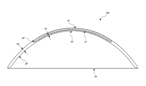
DETAILED DESCRIPTION
[0018] Figure 1 shows a schematic cross-sectional view of one
embodiment of a
hybrid contact lens 100. Though FIG. 1 only shows a cross-section, one of
skill in the art
will recognize that said cross-sectional view, when rotated 360 degrees about
its axis defines
the entire lens 100. The lens 100 can have a rigid gas permeable (RGP) portion
10 and a
flexible portion 30. In the illustrated embodiment, the RGP portion 10 can be
disposed
generally at the center of the hybrid contact lens 100 and the flexible
portion 30 can extend
outwardly from the RGP portion 10 and define an outer edge 34 of the hybrid
contact lens
100. The flexible portion 30 can also extend over an entire posterior surface
12 of the RGP
portion 10 so that the flexible portion defines the posterior surface 32 and
base curve of the
hybrid contact lens 100.The flexible portion 30 can optionally be hydrophilic.
[0019] The hybrid contact lens 100 can have a junction 50 defined
between the
RGP portion 10 and the flexible portion 30. Further details on the geometry of
the junction
50 can be found in US Patent Nos. 7097301, 7163292, 7104648, and 7322694.
[0020] The RGP portion 10 can be made of suitable contact materials,
such as
those disclosed in US Patent Nos. 7097301, 7163292, 7104648, and 7322694. In
one
embodiment, the RGP portion 10 can be made of Petrafocon A material. The
flexible portion
30 can be made of suitable contact lens materials, such as a Silicon Hydrogel
material and/or
those disclosed in US Patent Nos. 7097301, 7163292, 7104648, and 7322694. In
one
embodiment, the flexible portion 30 can be made of HEM-larafileon A material.
[0021] In one embodiment, the RGP portion 10 can have a gas
permeability Dk
value of greater than 30 barrer (i.e., greater than 30 x 101 I (ern2/see)(mL
02)/(mL x mm
Hg)), such as between 30-250 barrer. In another embodiment, the RGP portion 10
can have a
gas permeability Dk value of greater than 100 barrer, such as between 100-150
barrer. In still
another embodiment, the RGP portion 10 can have a gas permeability Dk value of
about 130
barrer.
[0022] In one embodiment, the flexible portion 30 can have a gas
permeability Dk
value of greater than 30 barrer (i.e., greater than 30 x 1041 (ciesec)(mL
02)/(mL x mm
Hg)). In another embodiment, the flexible portion 30 can have a gas
permeability Dk value
-4-
CA 2938007 2019-06-03
CA 02938007 2016-07-26
WO 2015/116456 PCT/US2015/012308
of greater than 50 barrer, such as between 50-100 Wirer. In still another
embodiment, the
flexible portion 30 can. have a gas permeability Dk value of about 80 barrer.
100231 In one embodiment, the flexible portion 30 defines a section 31
with
thickness T1 adjacent the posterior surface 12 of the RGP portion 10, so that
said thickness
Ti defines the section of the flexible portion 30 that extends posterior of
the RGP portion 10.
In one embodiment, the thickness Ti can be between about 10-350 microns, such
as between
50-100 microns. In another embodiment, the thickness Ti can be between 50-75
microns,
such as about 50 microns. However, in still other embodiments, the thickness
Ti can be less
than 50 microns. The hybrid contact lens 100 can have an RGP portion 10 with a
thickness
of between about 25 microns and about 500 microns, and a flexible portion with
a thickness
of between about 25 microns and about 500 microns, so that the hybrid contact
lens 100 can
have a total thickness T2 of between about 50 microns and about 1000 microns,
such as
about 300 microns. In another embodiment, the hybrid contact lens 100 can have
a total
thickness T2 of about 350 microns. The RGP portion I 0 can have a thickness
equal to the
total thickness T1 minus the thickness T1 of the flexible portion 30 adjacent
the posterior
surface 12 of the RGP portion 10.
EXAMPLES
00241 In the following examples, various samples of hybrid contact
lenses 100
were made using the methods described herein. The examples highlight the
performance of
such lenses, each having a different thickness for the RGP portion 10 and
flexible portion 30
in achieving a desired base curve and power for the lens design. These
examples are
discussed for illustrative purposes and should not be construed to limit the
embodiments of
the invention.
Test Desired Desired Total Flexible RGP Ratio Result
No. Base Power lens portion thickness T3/T1
Curve thickness layer Ti T3=T2-T1
(inni) T2 (pm) thickness (1.1m)
(11m)
1 7.5 -3.00 240 100 140 1.4 Fail
= 7.5 -3.00 200 50 150 3.0 Good
3 7.5 -3.00 200 150 50 0.33 Fafl
-5-
CA 02998007 2016-07-26
WO 2015/116456 PCT/US2015/012308
4 7.5 -3.00 290 50 240 4.8 Good
7.5 -3.00 340 50 290 5.8 Good
[00251 Through the testing noted above, Applicant discovered that the
ratio of the
thickness of the RGP portion 10 to the thickness Ti of the flexible portion
adjacent the
posterior surface 12 of the RGP portion 10 is an important variable. Applicant
further
discovered that to achieve desired lens design parameters, the ratio of the
thickness of the
RGP portion 10 to the thickness T1 of the flexible portion adjacent the
posterior surface 12
of the RGP portion 10 has to be at least 2 to 1 (such as 3 to 1,4 to 1, 5 to
1,6 to 1, etc.).
[0026) In some embodiments, the hybrid contact lens 100 can optionally
include
an optical, non-optical, or medical device encapsulated between the RGP
portion 10 and the
flexible portion 30. As shown in FIG. IA, a device 20 can be interposed or
encapsulated
between the posterior surface 12 of the RGP portion 10 and the section 31 of
the flexible
portion 30 that extends over the posterior surface 12. Though FIG. IA only
shows a cross-
sectional view of the lens 100, one of skill in the art will recognize that
the features shown in
FIG. IA extend about the axis of the lens 100 so that the RGP portion 10 and
flexible portion
30, as well as the device 20 can have a substantially circular profile when
the lens 100 is
viewed from above. That is, though FIG. IA only shows a cross-section, one of
skill in the
art will recognize that said cross-sectional view, when rotated 360 degrees
about its axis
defines the entire lens 100. Further, one of skill in the art will recognize
that the hybrid
contact lens 100 shown in FIG. IA can be manufactured using the same process
described
below, and only adds the additional step of incorporating the device 20
between posterior
surface 12 of the RGP portion 10 and the section 31 of the flexible portion
30.
100271 In one embodiment, the device 20 can be an optical device, such
as a lens
or filter. In another embodiment, the device 20 can be a non-optical device,
such as colored
element that provides for a colored contact lens and which advantageously
avoids the need to
paint a surface of the contact lens 100 to provide the color effect, and
therefore inhibits
possible leeching of ink into the eye. In another embodiment, the device 20
can be a medical
device to measure or detect/monitor one or more health parameters of the user.
For example,
in one embodiment, the sensor can be a pressure sensor. In another embodiment,
the sensor
can sense a quality of the tear fluid in the user's eye.
-6-
CA 02938007 2016-07-26
WO 2015/116456 PCT/US2015/012308
100281 In one embodiment the posterior surface 12 of the RGP portion 10
can
define a single optical zone (e.g., having a single optical power). In another
embodiment, the
posterior surface 12 of the RGP portion 10 can define multiple optical zones
having multiple
optical powers (e.g., dual optical zones having two optical powers). In the
embodiment
where th.e RGP portion 10 defines a single optical zone, the base curve of the
posterior
surface 12 of the RGP portion 10 and the base curve of the posterior surface
32 of the
flexible portion 30 can be substantially the same (e.g., identical). In the
embodiment where
the RGP portion 10 defines multiple optical zones, the base curve of the
posterior surface 12
of th.e RGP portion 10 and the base curve of the posterior surface 32 of the
flexible portion
30 can be different. Further discussion of multifocal zones in a hybrid
contact lens can be
found in US Patent 7,018,039, which is incorporated by reference in its
entirety and should
be considered a part of this specification.
[00291 FIGS. 2-5 show several steps in one embodiment of a manufacturing
process for making the hybrid contact lens 100. In the illustrated embodiment,
the
manufacturing process can be a casting process. As shown in FIG. 2, an RGP
button 200 can
be attached to a cup 300 having a cup body 310 that defines a cavity 330. The
RGP button
200 can be attached to the cup 300 with an adhesive. The RGP cup 200 can
define a junction
surface 52 that will form part of the junction 50 of the hybrid contact lens
100. In the
illustrated embodiment, the cavity 330 is empty. FIG. 2 shows a cross-section
of the cup
300, but one of skill in the art will recognize that said cross-sectional
view, when rotated 360
degrees about its axis defines the entire cup 300.
100301 With reference to FIG. 3, the posterior surface or base curve 12
can be
machined in the RGP button 200. For example, a lathe can be used to machine
the posterior
surface or base curve 12 into the RGP button 200. In the illustrated
embodiment, the cavity
330 is empty. As discussed above, in one embodiment, said machining of the
base curve 12
in the RGP button 200 can define a single optical zone to provide a single
lens system. In
another embodiment, said machining of the base curve 12 in the RGP button 200
can define
multiple optical zones (e.g., dual zones) to provide a multiple lens system
(e.g., dual lens
system). FIG. 3 shows a cross-section of the cup 300 and RGP button 200, but
one of skill in
the art will recognize that said cross-sectional view, when rotated 360
degrees about its axis
defines the entire cup 300 and RGP button 200.
-7-
[0031] Optionally, a chemical agent (such as those described in US
Patent Nos.
7097301, 7163292, 7104648, and 7322694) can be introduced into the cavity 300
so that it
contacts the RGP button, including the base curve 12 and junction surface 52.
In one
embodiment, the chemical agent can facilitate preparation of the RGP material
of the button
200 for bonding with the later introduced flexible material 400 (as shown in
FIG. 4). In one
embodiment, the chemical agent can be left in the cavity 330 for a
predetermined period of
time and then removed. In one embodiment, the longer the chemical agent
remains in the
cavity 330 the more it permeates through surfaces of the RGP button 200. In
one
embodiment, the period of time can be about 2 minutes. In another embodiment,
the
predetermined period of time can be about 1 minute. In still another
embodiment, the
predetermined period of time can be less than one minute. In still another
embodiment, the
step of introducing the chemical agent into the cavity 330 to treat the RGP
button 200 can be
excluded.
[0032] With reference to FIG. 4, the flexible material 400 is
introduced into the
cavity 330 so that it optionally fills the cavity 300, extends into the space
defined by the base
curve 12 in the RGP button 200 and adjacent the junction surface 52. The
flexible material
400 is casted to allow it to solidify. FIG. 4 shows a cross-section of the cup
300 and RGP
button 200, but one of skill in the art will recognize that said cross-
sectional view, when
rotated 360 degrees about its axis defines the entire cup 300 and RGP button
200.
[0033] With reference to FIG. 5, the casted flexible material 400 is
machined to
define the posterior surface or base curve 32 (and outer boundary 34) of the
flexible portion
30 of the hybrid contact lens 100. In one embodiment, a lathe can be used to
machine the
posterior surface or base curve 32 in the flexible material 400. FIG. 5 shows
a cross-section
of the cup 300 and RGP button 200, but one of skill in the art will recognize
that said cross-
sectional view, when rotated 360 degrees about its axis defines the entire cup
300 and RGP
button 200, base curve 32 and outer boundary 34.
[0034] Once the base curve 32 has be machined, the front or anterior
curve of the
RGP button 200 and flexible material 400 can be machined, using processes
known in the art,
to produce the final hybrid contact lens 100.
[0035] While certain embodiments of the inventions have been
described, these
embodiments have been presented by way of example only, and are not intended
to limit the
-8-
CA 2938007 2020-01-20
CA 02938007 2016-07-26
WO 2015/116456 PCT/US2015/012308
scope of the disclosure. Indeed, the novel methods and systems described
herein may be
embodied in a variety of other forms. Furthermore, various omissions,
substitutions and
changes in the systems and methods described herein may be made without
departing from
the spirit of the disclosure. The accompanying claims and their equivalents
are intended to
cover such forms or modifications as would fall within the scope and spirit of
the disclosure.
Accordingly, the scope of the present inventions is defined only by reference
to the appended
claims.
100361 Features, materials, characteristics, or groups described in
conjunction
with a particular aspect, embodiment, or example are to be understood to be
applicable to
any other aspect, embodiment or example described in this section or elsewhere
in this
specification unless incompatible therewith. All of the features disclosed in
this specification
(including any accompanying claims, abstract and drawings), and/or all of the
steps of any
method or process so disclosed, may be combined in any combination, except
combinations
where at least some of such features and/or steps are mutually exclusive. The
protection is
not restricted to the details of any foregoing embodiments. The protection
extends to any
novel one, or any novel combination, of the features disclosed in this
specification (including
any accompanying claims, abstract and drawings), or to any novel one, or any
novel
combination, of the steps of any method or process so disclosed.
100371 Furthermore, certain features that are described in this
disclosure in the
context of separate implementations can also be implemented in combination in
a single
implementation. Conversely, various features that are described in the context
of a single
implementation can also be implemented in multiple implementations separately
or in any
suitable subcombination. Moreover, although features may be described above as
acting in
certain combinations, one or more features from a claimed combination can, in
some cases,
be excised from the combination, and the combination may be claimed as a
subcombination
or variation of a subcombination.
[00381 Moreover, while operations may be depicted in the drawings or
described
in the specification in a particular order, such operations need not be
performed in the
particular order shown or in sequential order, or that all operations be
performed, to achieve
desirable results. Other operations that are not depicted or described can be
incorporated in
the example methods and processes. For example, one or more additional
operations can be
-9-
CA 02938007 2016-07-26
WO 2015/116456 PCT/US2015/012308
performed before, after, simultaneously, or between any of the described
operations. Further,
the operations may be rearranged or reordered in other implementations. Those
skilled in the
art will appreciate that in some embodiments, the actual steps taken in the
processes
illustrated and/or disclosed may differ from those shown in the figures.
Depending on the
embodiment, certain of the steps described above may be removed, others may be
added.
Furthermore, the features and attributes of the specific embodiments disclosed
above may be
combined in different ways to form additional embodiments, all of which fall
within the
scope of the present disclosure. Also, the separation of various system
components in the
implementations described above should not be understood as requiring such
separation in all
implementations, and it should be understood that the described components and
systems can
generally be integrated together in a single product or packaged into multiple
products.
[00391 For purposes of this disclosure, certain aspects, advantages, and
novel
features are described herein. Not necessarily all such advantages may be
achieved in
accordance with any particular embodiment. Thus, for example, those skilled in
the art will
recognize that the disclosure may be embodied or carried out in a manner that
achieves one
advantage or a group of advantages as taught herein without necessarily
achieving other
advantages as may be taught or suggested herein.
[00401 Conditional language, such as "can," "could," "might," or "may,"
unless
specifically stated otherwise, or otherwise understood within the context as
used, is generally
intended to convey that certain embodiments include, while other embodiments
do not
include, certain features, elements, and/or steps. Thus, such conditional
language is not
generally intended to imply that features, elements, and/or steps are in any
way required for
one or more embodiments or that one or more embodiments necessarily include
logic for
deciding, with or without user input or prompting, whether these features,
elements, and/or
steps are included or are to be performed in any particular embodiment.
[00411 Conjunctive language such as the phrase "at least one of X, Y,
and Z,"
unless specifically stated otherwise, is otherwise understood with the context
as used in
general to convey that an item, term, etc. may be either X, Y, or Z. Thus,
such conjunctive
language is not generally intended to imply that certain embodiments require
the presence of
at least one of X, at least one of Y, and at least one of Z.
-10-
CA 02938007 2016-07-26
WO 2015/116456 PCT/US2015/012308
100421 Language of degree used herein, such as the terms
"approximately,"
"about," "generally," and "substantially" as used herein represent a value,
amount, or
characteristic close to the stated value, amount, or characteristic that still
performs a desired
function or achieves a desired result. For example, the terms "approximately",
"about",
"generally.," and "substantially" may refer to an amount that is within less
than 10% of,
within less than 5% of, within less than 1% of, within less than 0.1% of, and
within less than
0.01% of the stated amount. As another example, in certain embodiments, the
terms
"generally parallel" and "substantially parallel" refer to a value, amount, or
characteristic
that departs from exactly parallel by less than or equal to 15 degrees, 10
degrees, 5 degrees, 3
degrees, 1 degree, 0.1 degree, or otherwise.
[00431 The scope of the present disclosure is not intended to be limited
by the
specific disclosures of preferred embodiments in this section or elsewhere in
this
specification, and may be defined by claims as presented in this section or
elsewhere in this
specification or as presented in the future. The language of the claims is to
be interpreted
broadly based on the language employed in the claims and not limited to the
examples
described in the present specification or during the prosecution of the
application, which
examples are to be construed as non-exclusive.
-11-