Note: Descriptions are shown in the official language in which they were submitted.
CA 02938083 2016-08-05
PROCESS FOR GAS SEPARATIONS USING ZEOLITE SSZ-13
FIELD
The present disclosure relates to methods for treating methane-containing gas
mixtures involving the use of adsorbent zeolite particles to adsorb acid gases
from the gas
mixtures.
BACKGROUND
Natural gas typically requires treatment to remove acid gas contamination
including
carbon dioxide (CO2) and hydrogen sulfide (H2S) before utilization of the
natural gas. As
natural gas production continues to grow in remote areas and in gas fields
containing acid
gases, there is a need to treat natural gas produced from these fields using
efficient methods
to remove such contaminants. To treat acid gases, aqueous amine absorption is
the standard
technology because of high recovery of hydrocarbons and efficient energy use.
However,
amine absorption technology may not be feasible or practical when treating
natural gas at the
well head or at low flow rates. Amine absorption technology has issues
associated with
handling solvents required for regeneration, and has poor economics in remote
or offshore
locations. Practical use of amine absorption technology would require
absorption of acid
gases at mild temperatures, heating the solvent to high temperatures to remove
the acid gases
in a stripping tower, and subsequent cooling of the solvent to return to the
absorption unit.
The natural gas product from the amine unit further requires a dehydration
step to remove
water for dew point control.
Pressure-swing adsorption (PSA) technology is an alternative technology for
treating
natural gas that uses a solid adsorbent material to remove acid gases. PSA
technology
operates by using an adsorbent material that removes a target adsorbate
molecule from a gas
mixture by preferential adsorption over other species in the gas mixture.
Adsorption
processes that remove CO2 from gas streams typically use zeolite- or carbon-
based adsorbent
materials. The adsorbent can either function by equilibrium (thermodynamics)
or kinetic
(rate-based) separations. In principle, all adsorption processes utilize at
least two steps:
adsorption or uptake of the target molecule in the adsorbent; and desorption
or removal of
that same target molecule from the adsorbent. This may be achieved by changes
in
concentration, pressure, or temperature. In the case of PSA and vacuum-swing
adsorption
1
(VSA), pressure changes are used to regenerate the adsorbent. PSA does not
require a
dehydration step. PSA technology is able to treat natural gas containing acid
gases without
the need for on-site solvent regeneration and other issues associated with
amine units.
It would be desirable to have a PSA process utilizing an adsorbent material
which
.. would require lower vacuum power consumption and which would allow improved
hydrocarbon recoveries as compared with known processes. Such a process would
enable
deployment and competitive use of PSA units for natural gas separations in
expanded
applications.
SUMMARY
In one aspect, a method is provided for removing acid gas from a feed gas
stream of
natural gas including acid gas, methane and ethane. The method includes
alternating input of
the feed gas stream between at least two beds of adsorbent particles
comprising zeolite SSZ-
13 such that the feed gas stream contacts one of the at least two beds at a
given time in an
adsorption step and a tail gas stream is simultaneously vented from another of
the at least two
beds in a desorption step. The contact occurs at a feed pressure of from about
50 to about
1000 psia for a sufficient period of time to preferentially adsorb acid gas
from the feed gas
stream. A product gas stream is produced containing no greater than about 2
mol% carbon
dioxide and at least about 65 mol % of methane recovered from the feed gas
stream and at
least about 25 mol % of ethane recovered from the feed gas stream. The feed
gas stream is
input at a feed end of each bed. The product gas stream is removed from a
product end of
each bed. The tail gas stream is vented from the feed end of each bed.
In accordance with another aspect, there is a method for removing acid gas
from a feed
gas stream of natural gas including acid gas, methane and ethane, comprising:
alternating input of the feed gas stream between at least two beds of
adsorbent
particles comprising zeolite SSZ-13 such that the feed gas stream contacts one
of the at least
two beds at a given time in an adsorption step and a tail gas stream is
simultaneously vented
from another of the at least two beds in a desorption step;
wherein the contact occurs at a feed pressure of from about 50 to about 1000
psia for a
sufficient period of time to preferentially adsorb acid gas from the feed gas
stream; thereby
producing a product gas stream containing about 2 mol % or no greater than 2
mol% carbon
dioxide and about 65 mol % or at least 65 mol % of methane recovered from the
feed gas
2
Date Recue/Date Received 2023-07-18
stream and about 25 mol % or at least 25 mol % of ethane recovered from the
feed gas
stream; and
wherein the feed gas stream is input at a feed end of each bed; the product
gas stream is
removed from a product end of each bed; and the tail gas stream is vented from
the feed end
of each bed.
In accordance with a further aspect, there is a method for removing acid gas
from a feed
gas stream of natural gas including methane, ethane, carbon dioxide and from 4
to 1000 ppm
hydrogen sulfide, comprising:
alternating input of the feed gas stream between at least two beds of
adsorbent particles
comprising zeolite SSZ-13 such that the feed gas stream contacts one of the at
least two beds
at a given time in an adsorption step and a tail gas stream is simultaneously
vented from
another of the at least two beds in a desorption step;
wherein the contact occurs at a feed pressure of from about 50 to about 1000
psia for a
sufficient period of time to preferentially adsorb acid gas from the feed gas
stream; thereby
producing a product gas stream containing about 2 mol % or no greater than 2
mol % carbon
dioxide, about 1 ppm or no greater than 1 ppm H2S, about 1 ppm or no greater
than 1 ppm
COS, and about 65 mol % or at least 65 mol % of methane recovered from the
feed gas
stream and about 25 mol % or at least 25 mol % of ethane recovered from the
feed gas
stream; and
wherein the feed gas stream is input at a feed end of each bed; the product
gas stream is
removed from a product end of each bed; and the tail gas stream is vented from
the feed end
of each bed.
In accordance with a further aspect, there is a method for removing an acid
gas from a
feed gas stream of a natural gas including the acid gas, a methane and an
ethane, comprising:
alternating input of the feed gas stream between at least two beds of
adsorbent particles
made from a homogeneous mixture comprising a zeolite SSZ-13 such that the feed
gas
stream contacts one of the at least two beds at a given time in an adsorption
step and a tail gas
stream is simultaneously vented from another of the at least two beds in a
desorption step;
wherein a contacting of the feed gas stream occurs at a feed pressure of from
about 50 to
about 1000 psia for a sufficient period of time to preferentially adsorb the
acid gas from the
feed gas stream; thereby producing a product gas stream containing about 2 mol
% or no
greater than 2 mol % carbon dioxide and about 65 mol % or at least 65 mol % of
the methane
2a
Date Recue/Date Received 2023-07-18
recovered from the feed gas stream and about 25 mol % or at least 25 mol % of
the ethane
recovered from the feed gas stream; and
wherein the feed gas stream is input at a feed end of each of the at least two
beds; the
product gas stream is removed from a product end of each of the at least two
beds; and the
tail gas stream is vented from the feed end of each of the at least two beds.
In accordance with a further aspect, there is a method for removing an acid
gas from a
feed gas stream of a natural gas including the acid gas, a methane and an
ethane, comprising:
alternating input of the feed gas stream between at least two beds of
adsorbent particles
comprising a zeolite SSZ-13 such that the feed gas stream contacts one of the
at least two
beds at a given time in an adsorption step and a tail gas stream is
simultaneously vented from
another of the at least two beds in a desorption step;
wherein the at least two beds of adsorbent particles comprising the zeolite
SSZ-13 are
four beds of adsorbent particles comprising the zeolite SSZ-13,
wherein a contacting of the feed gas stream occurs at a feed pressure of from
about 50 to
about 1000 psia for a sufficient period of time to preferentially adsorb the
acid as from the
feed gas stream; thereby producing a product gas stream containing about 2 mol
% or no
greater than 2 mol % carbon dioxide and about 65 mol % or at least 65 mol % of
the methane
recovered from the feed gas stream and about 25 mol % or at least 25 mol % of
the ethane
recovered from the feed gas stream; and
wherein the feed gas stream is input at a feed end of each of the at least two
beds; the
product gas stream is removed from a product end of each of the at least two
beds; and the
tail gas stream is vented from the feed end of each of the at least two beds;
further comprising:
a. following a first adsorption step in a first bed of the four beds, a first
equalization step
occurs wherein the first bed is allowed to equalize in a pressure with a
second bed of the four
beds having a lower pressure than the first bed through a first line
connecting the product end
of the first bed and the product end of the second bed;
b. following the first equalization step, lowering the pressure in the first
bed and passing
a gas from the first bed to a third bed of the four beds through a second line
connecting the
product ends of the first bed and the product end of the third bed in a
providing purge step
such that the third bed of the four beds is purged;
c. following the providing purge step, a second equalization step occurs
wherein the first
bed is allowed to equalize in the pressure with the third bed of the four beds
having the lower
2b
Date Recue/Date Received 2023-07-18
pressure than the first bed through a third line connecting the product end of
the first bed and
the product end of the third bed;
d. following the second equalization step, depressurizing a first adsorbent
bed to the
pressure from about 20 to about 1 psia through the feed end of the first
adsorbent bed in a
blowdown step comprising either:
i. allowing the gas in the first adsorbent bed to vent to a purge tank; or
ii. using a vacuum pump to lower the pressure of the first adsorbent bed;
e. following the blowdown step, the first bed is purged in a purging step
wherein the gas
is provided to the first bed through the product end of the first bed from a
fourth bed of the
four beds while the first bed is at the pressure from about 20 to about 1 psia
and the gas is
purged through the feed end of the first bed;
f. following the purging step, a third equalization step occurs wherein the
first bed is
allowed to equalize in the pressure with the fourth bed having a higher
pressure than the first
bed through a fourth line connecting the product end of the first bed and the
product end of
the fourth beds;
g. following the third equalization step, a fourth equalization step occurs
wherein the first
bed is allowed to equalize with the second bed having the higher pressure than
the first bed
through a fifth line connecting the product end of the first bed and the
product end of the
second bed;
h. following the fourth equalization step, passing a slipstream of the product
gas stream
or a stream of gas from a storage tank through the product end of the first
bed to repressurize
the first bed to an adsorption step pressure in a repressurization step; and
i. following the repressurization step, operating the first bed in an
independent adsorption
step for sufficient time for the third bed and the fourth bed to be equalized
in the pressure and
the second bed to be depressurized prior to beginning a second adsorption
step;
wherein the second bed, the third bed, and the fourth bed are sequenced to
cycle through
the adsorption step, the first equalization step, the providing purge step,
the second
equalization step, the blowdown step, the purging step, the third equalization
step, the fourth
equalization step and the independent adsorption step in the same order as the
first bed.
In accordance with a further aspect, there is a method for removing an acid
gas from a
feed gas stream of natural gas including a methane, an ethane, a carbon
dioxide and from 4 to
1000 ppm hydrogen sulfide, comprising:
2c
Date Recue/Date Received 2023-07-18
alternating input of the feed gas stream of natural gas between at least two
beds of
adsorbent particles made from a homogeneous mixture comprising zeolite SSZ-13
such that
the feed gas stream of natural as contacts one of the at least two beds at a
given time in an
adsorption step and a tail gas stream is simultaneously vented from another of
the at least two
beds in a desorption step;
wherein a contacting of the feed gas stream of natural gas the contact occurs
at a feed
pressure of from about 50 to about 1000 psia for a sufficient period of time
to preferentially
adsorb the acid gas from the feed gas stream of natural gas; thereby producing
a product gas
stream containing about 2 mol % or no greater than 2 mol % of the carbon
dioxide, about 1
.. ppm or no greater than 1 ppm H2S, about 1 ppm or no greater than 1 ppm COS,
and about 65
mol % or at least 65 mol % of the methane recovered from the feed gas stream
of natural gas
and about 25 mol % or at least 25 mol % of the ethane recovered from the feed
gas stream of
natural gas; and
wherein the feed gas stream of natural gas is input at a feed end of each of
the at least
two beds; the product gas stream is removed from a product end of each of the
at least two
beds; and the tail gas stream is vented from the feed end of each of the at
least two beds.
DESCRIPTION OF THE DRAWINGS
These and other objects, features and advantages of the present invention will
become
better understood with reference to the following description, appended claims
and
accompanying drawings where:
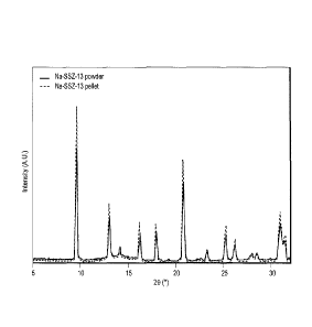
FIG. 1 is a plot comparing XRD patterns of samples of Na-SSZ-13 pellets with
Na-SSZ-
13 powder.
FIG. 2 is a schematic diagram illustrating a dynamic column breakthrough (DCB)
.. apparatus.
2d
Date Recue/Date Received 2023-07-18
CA 02938083 2016-08-05
FIGS. 3-7 show the equilibrium adsorption results for CO2, CF14, C2H6, H20 and
H2S,
respectively, according to exemplary embodiments.
FIG. 8 is a plot of enthalpy of adsorption for each natural gas component on
Na-SSZ-
13 according to exemplary embodiments.
FIGS. 9-16 are representative breakthrough curves comparing experimental and
simulation breakthrough behavior for Na-SSZ-13 according to exemplary
embodiments.
FIG. 17 is a plot of calculated breakthrough capacities for CO2 and C2H6
according to
exemplary embodiments.
FIG.18 is a representative breakthrough curve for a quaternary feed mixture
containing CO2, C2H6, H2S and CH4.
FIGS. 19 and 20 are a schematic diagram illustrating a two bed PSA system and
a
corresponding bed interaction scheme, respectively, according to one exemplary
embodiment.
FIGS. 21 and 22 are a schematic diagram illustrating a four bed PSA system and
a
.. corresponding bed interaction scheme, respectively, according to one
exemplary
embodiment.
FIG. 23 is a plot of pressure vs. time at different PP/F ratios, according to
exemplary
embodiments.
FIG. 24 is a plot of CO2 content in the product gas and recovery of
hydrocarbons vs.
PP/F ratio using Na-SSZ-13, according to exemplary embodiments.
FIG.25 is a plot of CO2 content in the product gas and recovery of
hydrocarbons vs.
1313/F ratio using Na-13X, a comparative example.
FIG. 26 is a plot of CO2 content in the product gas and C2H6 recovery vs.
vacuum
power using Na-SSZ-13, according to exemplary embodiments.
FIG. 27 is a plot of CO2 content in the product gas and C2H6 recovery vs.
vacuum
power using Na-13X.
3
FIG. 28 is a plot of CH4 recovery vs. recycle ratio, according to exemplary
embodiments.
FIG. 29 is a plot of CO2 content in the product gas and percent recovery of
hydrocarbons vs. the PP/F ratio, according to exemplary embodiments.
DETAILED DESCRIPTION
The methods of the present disclosure use SSZ-13 zeolite particles as an
adsorbent
material in a PSA process for removing acid gas from natural gas streams. The
acid gas can
include carbon dioxide (CO2), hydrogen sulfide (H2S), carbonyl sulfide (COS),
combinations
thereof, and combinations thereof with water (H20). In one embodiment, the
amount of
hydrogen sulfide in the feed gas stream is from 0 to 1000 ppm.
SSZ-13 is a synthetic chabazite (a CHA type zeolite), described more fully in
U.S.
Pat. No. 4,544,538, issued Oct. 1, 1985 to Zones. A method for preparing SSZ-
13 is
disclosed in U.S. Pat. No. 8,007,764 (Miller et al.). In one embodiment, the
SSZ-13 has a
ratio of silica to alumina (also referred to as Si:Al ratio) of from 5 to 100.
In one
embodiment, the zeolite SSZ-13 has a cation as a framework ion. Suitable
cations can
include sodium, calcium, potassium, lithium, magnesium, and barium. In one
embodiment,
the cation is a sodium cation.
In one embodiment, acid gas is removed from a feed gas stream of natural gas
including acid gas, methane and ethane. In one embodiment, the feed gas stream
is alternately
input between at least two beds of adsorbent particles comprising zeolite SSZ-
13 such that
the feed gas stream contacts one of the at least two beds at a given time. The
feed gas stream
is input at a feed end of each bed. In one embodiment, the feed gas stream has
a flow rate of
from 1 to 100 million standard cubic feet per day (MMSCFD) in an adsorption
step. The
adsorption step can occur at a temperature of from 20 to 80 C.
While the feed gas stream is contacting the adsorbent bed, the adsorbent bed
is
operating in the adsorption step_ A tail gas stream is simultaneously vented
from another of
the at least two beds in a desorption step. The tail gas stream is vented from
the feed end of
each bed. The contact of the gas with the adsorbent particles (in the
adsorption step) occurs at
4
Date Recue/Date Received 2022-09-08
CA 02938083 2016-08-05
a feed pressure of from about 50 to about 1000 psia fora sufficient period of
time to
preferentially adsorb acid gas from the feed gas stream. As feed pressure is
increased, the
moles of ethane (C2H6) adsorbed onto the adsorbent per mass of the adsorbent
decreases. A
principle of PSA operations is that the adsorbent is fed at higher pressures,
and the adsorbent
bed is regenerated at a lower pressure. In processes using conventional
adsorbents, C2H6
adsorbs more as pressure is increased, and during the desorption step, more
C2116 is lost
because desorption occurs at the lower pressures of desorption. In embodiments
of the
present disclosure, because C2H6 adsorbs more at lower pressures, it is not
lost in as great a
quantity in the tail gas as in processes using conventional adsorbents due to
the adsorption
behavior of SSZ-13, demonstrated herein experimentally in Example 3. Thus the
potential
recovery of the heavier hydrocarbon is increased in processes using SSZ-13 as
the adsorbent.
A product gas stream is produced as a result of the adsorption step. The
product gas
stream is removed from a product end of each bed. The product gas stream
contains no
greater than about 2 mol% carbon dioxide and at least about 65 mol % of
methane recovered
from the feed gas stream and at least about 25 mot % of ethane recovered from
the feed gas
stream. In one embodiment, the product gas stream contains methane having a
purity of at
least about 95 mot % and ethane having a purity of at least about 3 mol %
ethane. In one
embodiment, the product gas stream contains no greater than about 50 ppm
hydrogen sulfide.
In one embodiment, the product gas stream contains no greater than about 4 ppm
hydrogen
sulfide.
In one embodiment, following the adsorption step in one of the at least two
beds and
simultaneous desorption step in another of the at least two beds, the pressure
of the two beds
is allowed to equalize. This can be done by means of a line connecting the
product ends of
the two beds at the end of the adsorption step and simultaneous desorption
step. Following
the desorption step, the bed having just completed the desorption step is
repressurized by first
equalizing in pressure with a second bed of at least two beds and then further
repressurized
by another gas stream. This further repressurization can be done by sending a
slipstream of
the product gas stream through the product end of the bed having just
completed the
desorption step. In another embodiment, the further repressurization can be
done by utilizing
the feed gas through the feed end of the bed having just completed the
desorption step.
In one embodiment, two adsorbent beds are used. A PSA system 100 with two beds
is
shown in FIG. 19 with an adsorption cycle (bed interaction scheme) as shown in
FIG. 20.
5
CA 02938083 2016-08-05
Feed gas 101 is introduced into line 106 having block valves 105 therein. Line
106 connects
the feed ends 108A and 109A of adsorption columns 108 and 109, respectively.
Line 107 also
connects the feed ends 108A and 109A of adsorption columns 108 and 109,
respectively, and
has an outlet for tail gas 110. Adsorption columns 108 and 109 have product
ends 108B and
.. 109B, respectively. Product ends 108B and 109B are connected by lines 111
and 112. Lines
1 1 1 and 112 include block valves 105. Line 112 is connected with line 113
which delivers
gas to optional product gas buffer tank 114. The product gas buffer tank 114
allows
controlled purging and repressurization steps. Product gas 115 can be provided
from product
gas buffer tank 114 (controlled by a block valve 105) through line 116 to line
111. FIG. 20
illustrates the sequence of steps that each of the adsorption columns cycles
through. In one
embodiment, adsorption columns 108 and 109 alternate, such that while one
adsorption
column, column 108, is operating in the adsorption step, the other adsorption
column, column
109, is operating in the desorption step. Following the adsorption step in the
first bed, the bed
having just finished the adsorption step is depressurized through the product
end of the bed,
line 111, while feeding gas to the second bed having just completed the
desorption step
through the product end of the bed, line 112. When the pressures have
equalized in the two
beds, the first bed is then depressurized through the feed end of the bed from
about 20 psia to
about 1 psia, line 110, and the second bed is simultaneously repressurized
using a product gas
buffer tank 114 through line 116.
In one embodiment, four adsorbent beds are used and the adsorbent beds are
controlled in such a way that each bed cycles through a sequence of
operations, also referred
to as steps, and the cycles of the four beds are synchronized with respect to
one another. FIG.
21 illustrates such a system 200. The operation of system 200 is similar to
the operation of
the two bed system 100. Feed gas 201 is introduced into line 206 having block
valves 208
therein. Line 206 connects the feed ends 202A, 203A, 204A and 205A of
adsorption columns
202, 203, 204 and 205, respectively. Line 207 also connects the feed ends
202A, 203A, 204A
and 205A of adsorption columns 202, 203, 204 and 205, respectively, and has an
outlet for
tail gas 210. Adsorption columns 202, 203, 204 and 205 have product ends 202B,
203B,
204B and 205B, respectively. Product ends 202B, 203B, 204B and 205B are
connected by
lines 209, 211, 212 and 213. Lines connecting product ends 202B, 203B, 204B
and 205B
with lines 209, 211, 212 and 213 include block valves 208. Lines 209 and 213
are connected
with optional product gas buffer tank 214. The product gas buffer tank 214
allows controlled
6
CA 02938083 2016-08-05
=
purging and repressurization steps. Product gas 215 can be provided from
product gas buffer
tank 214 (controlled by a block valve 208).
FIG. 22 illustrates the sequence of steps that each of the four adsorption
columns
cycles through in an embodiment using the system 200. The cycle of steps that
each bed is
sequenced through will be described as follows, from the perspective of one of
the four beds,
arbitrarily designated herein as the "first bed" or "Bed 1." Following a first
adsorption step
(illustrated as "ADS" in the matrix of FIG. 22) in the first bed, a first
equalization step
(illustrated as "EQ1- in the matrix) occurs in which the first bed is allowed
to equalize in
pressure with a second bed of the four beds. The second bed has a lower
pressure than the
first bed, so that when the two beds equalize, the pressure of the first bed
reduces and the
pressure of the second bed increases. The equalization can occur through a
line connecting
the product ends of the first and the second beds.
Following the above-described first equalization step, the pressure in the
first bed is
lowered and gas is passed from the first bed to a third bed of the four beds
through a line
connecting the product ends of the first and the third beds. This is referred
to as the
"providing purge" step ("PP") since the gas purges the third bed.
Following the providing purge step, a second equalization step ("EQ2") occurs
in
which the first bed is allowed to equalize in pressure with the third bed. The
third bed has a
lower pressure than the first bed. The pressure of the first and third beds
equalizes through a
line connecting the product ends of the first and the third beds.
Following the second equalization step, the first adsorbent bed is next
depressurized
to a pressure of from about 20 to about 1 psia through the feed end of the
first adsorbent bed.
This is referred to as the blowdown step ("BD") in which gas in the first
adsorbent bed is
allowed to vent to a purge tank. Alternatively, a vacuum pump can be used to
lower the
pressure of the first adsorbent bed in this step.
Following the blowdown step, the first bed is purged in a purging step ("PU")
in
which gas is provided to the first bed through the product end of the first
bed from a fourth
bed of the four beds while the first bed is at a pressure from about 20 to
about 1 psia. Gas is
meanwhile purged through the feed end of the first bed during the purging
step.
7
CA 02938083 2016-08-05
Following the purging step, a third equalization step ("EQ2") occurs in which
the first
bed is allowed to equalize in pressure with the fourth bed. The fourth bed has
a higher
pressure than the first bed. The pressure equalization can occur through a
line connecting the
product ends of the first and the fourth beds.
Following the third equalization step, a fourth equalization step ("EQ1")
occurs in
which the first bed is allowed to equalize with the second bed which has a
higher pressure
than the first bed. This equalization step can occur through a line connecting
the product ends
of the first and the second beds.
Following the fourth equalization step, a slipstream of the product gas is
passed
through the product end of the first bed to repressurize the first bed to the
adsorption step
pressure in a repressurization step ("RP").
Following the repressurization step, the first bed is operated in an
independent
adsorption step (illustrated as a blank box in the matrix) for sufficient time
for the third and
fourth beds to be equalized in pressure with respect to one another, and for
the second bed to
be depressurized. After this period of time, a second adsorption step can
begin.
The second, third and fourth beds are likewise sequenced to cycle through the
above-
described adsorption step, first equalization step, providing purge step,
second equalization
step, blowdown step, purging step, third equalization step, fourth
equalization step and
independent adsorption step in the same order as the first bed. In one
embodiment, the
adsorption step, first equalization step, providing purge step, second
equalization step,
blowdown step, purging step, third equalization step, fourth equalization step
and
independent adsorption step occur in a total cycle time of from 400 to 3600
seconds, even
from 400 to 1600 seconds.
In one embodiment, the product gas stream contains at least about 80 mol% of
methane
recovered from the feed gas stream and at least about 40 mol% of ethane
recovered from the
feed gas stream.
In one embodiment, recycle of the waste stream from the blowdown and purge
steps
can be used to increase the CH4 and C2H6 recoveries and lower the vacuum and
compression
costs. Thus processes according to some embodiments are suitable for removing
acid gases
8
CA 02938083 2016-08-05
from natural gas streams in remote or off-shore locations if amine absorption
is not a viable
alternative for separations.
In some embodiments, the methods of the present disclosure have a specific
vacuum
power consumption of from about 500 to about 1500 kWhr/MM SCF raw gas.
In some embodiments, from greater than 0% to about 50% of the tail gas stream
is
recycled to the feed gas stream. As a result, a product gas stream is produced
containing no
greater than about 2 mol% carbon dioxide and at least about 90 mol % of the
methane in the
feed gas stream and at least about 85 mol % of the total hydrocarbons in the
feed gas stream.
In some embodiments, a method is provided for removing acid gas from a feed
gas
stream of natural gas that includes methane, ethane, carbon dioxide and from 4
to 1000 ppm
hydrogen sulfide. The feed gas stream is alternately input between at least
two beds (input at
a feed end of each bed) of adsorbent particles comprising zeolite SSZ-13 such
that the feed
gas stream contacts one of the at least two beds at a given time in an
adsorption step and a tail
gas stream is simultaneously vented from another of the at least two beds
(from the feed end)
in a desorption step. The contact occurs at a feed pressure of from about 50
to about 1000
psia for a sufficient period of time to preferentially adsorb acid gas from
the feed gas stream.
As a result, advantageously, a product gas stream is produced (removed from a
product end
of each bed) containing no greater than about 2 mol% carbon dioxide, no
greater than about 1
ppm H2S, and no greater than about 1 ppm COS. At least about 65 mol % of
methane is
.. recovered from the feed gas stream and at least about 25 mol % of ethane is
recovered from
the feed gas stream.
It should be noted that only the components relevant to the disclosure are
shown in
the figures, and that many other components normally part of a pressure-swing
or vacuum-
swing adsorption system are not shown for simplicity.
9
CA 02938083 2016-08-05
EXAMPLES
TEST METHODS
Powder x-ray diffraction (XRD) was performed with Cu X-ray source and measured
between 5 and 35 2-theta (20).
BET and t-plot micropore volume were determined by N2 physisorption
experiments.
The Na-SSZ-13 samples were activated at 400 C under flowing N2 gas. The
samples were
then cooled to -196 C and uptake of N, was measured.
Pellet density was determined by preparing a volumetric solution of water,
submerging Na-SSZ-13 pellets of a known mass into the water solution and
calculating
.. density based on changes in volume.
The skeletal density determined from crystal structure of CHA was calculated
based
on the Si:Al ratio and the sodium cation. The unit cell volume and framework
density were
obtained from the IZA database.
Example 1: Preparation of SSZ-13
Na-SSZ-13 powder was synthesized based on previous procedures to produce a CHA
(three letter code standing for chabazite, provided by the International
Zeolite Association
[IZA]) structure with a Si:Al atomic ratio of 6.8 as described in U.S. Patent
No. 6,709,644
(Zones et al.)). Na-SSZ-13 pellets were prepared by mixing with pseudo-
Boehmite alumina
powder to achieve 25 wt% alumina, grinding the powders together to create a
homogeneous
mixture and then pressing pellets at 15,000 psi. The alumina binder provides
support to the
zeolite pellets. The pellets were broken and sieved to obtain the desired mesh
size. Multiple
pellets were prepared for use in dynamic column breakthrough (DCB)
experiments. The Na-
SSZ-13 pellet samples were analyzed for BET and t-plot micropore volume
analysis
following DCB experiments to confirm the adsorbents are fully regenerable and
stable after
multiple adsorption experiments.
The powder XRD pattern of the Na-SSZ-13 pellet samples is shown in FIG. I. The
XRD pattern matched the expected CHA structure. The CHA structure remained
intact after
preparing pellets under a high-pressure pellet press, showing the distinct
structural peaks
between 5-35 (degrees) 20 (theta). Table 1 shows the characterization of the
Na-SSZ-13
CA 02938083 2016-08-05
powder, pellet and spent pellet. BET and t-plot MPV reflect typical Cl-IA
textural properties
for Na-SSZ-13 powder. There was no apparent change in the normalized micropore
volume
when the amount of binder is taken into account, further confirming the CHA
structure
remained stable after pellet preparation and exposure to different gases at
various feed
pressures and activation cycles.
Table 1
Na-SSZ-13
Na-SSZ-13 Pellet Na-
SSZ-13 Spent Pellet
Powder
BET Surface Area
610 530 530
(m2/0
t-plot MPV
0.282 0.213 (0.284)a 0.214 (0.284)a
(cm3/g)
Pellet Density
920
(kg/m3)
Skeletal Density
1550
(kg/m3)
a: Values for t-plot MPV in parentheses represented micropore volume
normalized to amount
of zeolite.
Example 2: Pure Component Equilibrium Adsorption
Equilibrium gas adsorption experiments for CO2, CH4 and C2H6 were performed on
a
SETARAM PCTPro 2000 volumetric system (commercially available from SETARAM
INSTRUMENTATION, Caluire, France). Equilibrium vapor adsorption experiments
for H20
were performed on a dynamic vapor sorption (DVS) vacuum gravimetric system
(commercially available from SURFACE MEASUREMENT SYSTEMS, London, United
Kingdom). Na-SSZ-13 samples were first activated at 250 C to obtain the dry
weight and
then reactivated in the gas adsorption system. Gases used were CO2, CH4, C2H6
and He (all
99.999%). The zeolites were tested from 0-30 bar for CO2 and CH4 and 0-3 bar
for C21-16. For
vapor experiments, the pressure ranged up to 280 mbar due to the limitation in
generating
vapor pressure up to 70 C.
For H2S adsorption measurements, the adsorption capacity was determined by
dynamic column breakthrough (DCB) experiments using the DCB apparatus shown in
FIG. 2
11
CA 02938083 2016-08-05
and described in Example 3. Gas mixtures of 1000 ppm H2S in helium were fed to
Na-SSZ-
13 zeolite pellets at 350 cm3 (STP)/min from pressures of 1.6 to 35 bar to
obtain isotherms at
different H2S partial pressures. The capacity was determined by calculating
the breakthrough
time for H2S by equation (1).
Th dt (1)
0
F1,1,
where Fl is the molar flow rate of the gas component being considered at the
outlet, o, and
feed, f. To determine the breakthrough capacity, the methodology developed by
Malek and
Farooq in A. Malek, S. Farooq, "Determination of Equilibrium Isotherms Using
Dynamic
Column Breakthrough and Constant Flow Equilibrium Desorption", J. Chem. Eng.
Data,
1996, 41, 25-32 was used. Using the methodology, the capacity is calculated by
equation (2).
= C, Ep r v,r, 1\
qb (2)
pp 1-- cp 1
where qb is the breakthrough capacity, Ci is the gas step concentration of
component i, pp is
the particle density, ep is the bed void fraction, vi is the interstitial
velocity, 1 is the length of
the packed bed and tb is the effective breakthrough time.
FIGS. 3-7 show the equilibrium adsorption results for CO2, CH4, C21-16, F120
and H2S,
respectively. Lines represent the fit of the dual-site Langmuir isotherm
equation. FIG. 3 plots
CO2 equilibrium adsorption isotherms at 30-80 C. FIG. 4 plots CH4 equilibrium
adsorption
isotherms at 30-80 C. FIG. 5 plots C2H6 equilibrium adsorption isotherms at
30-89 C. FIG.
6 plots H20 equilibrium adsorption isotherms at 30-100 C. FIG. 7 plots H2S
equilibrium
adsorption isotherms at 30-80 C. FIGS. 3-7 represent either major hydrocarbon
components
or major impurities found in natural gas wells with CO2, CH4 and C2H6 making
up 60-90
vol% of most natural gas wells. If an adsorbent is capable of separating CH4
and C2H6 from
CO2, most hydrocarbons may be recovered, especially in application of lean gas
mixtures,
where very little heavier hydrocarbon components are found. Because the Na-SSZ-
13 has a
lower amount of aluminum in the zeolite framework, the CO2 adsorption
isotherms do not
show saturation at moderate temperatures until the CO2 pressure reaches above
10 bar. The
C2H6 adsorption isotherms show much lower saturation pressures with very
little increase in
adsorbed capacity above 1 bar of pressure. Although the SSZ-13 sample used in
this Example
has a higher SAR than typical adsorbents, such as zeolites 5A, Na-X or Na-Y,
the H20
12
CA 02938083 2016-08-05
adsorption affinity was found to be quite high. Further increasing the SAR may
lower the
overall affinity for water. The H2S adsorption isotherms determined from
breakthrough
experiments showed very high adsorption affinity. The adsorption affinity for
Na-SSZ-13 is
of the order: H20> H2S > CO2> C2116> CH. The ideal selectivity of both gas
pairs, CO2/
C2H6 and CO2/ CH4, is 1.7 and 44 at 30 C. The enthalpy of adsorption for each
natural gas
component on Na-SSZ-13 is shown in FIG. 8.
Gases with lower molecular weight or lower polarity show significantly lower
enthalpies of adsorption compared to components like H2S and H20 that have
extremely high
polarity, and the heat of adsorption correlates with adsorption affinity. For
processing natural
gas containing these components, it is expected that gas streams containing
significant
amounts of CO2, H2S or H20 will generate rises in temperature inside the
adsorption bed
when removing these components during an adsorption cycle.
Example 3: Dynamic Column Breakthrough (DCB) Adsorption Performance
Dynamic adsorption experiments were carried out on a custom-built DCB
apparatus,
as shown in FIG. 2. Three lines 1, 2 and 3 were provided for test gases to be
fed to the
apparatus and metered using mass flow controllers 4. Block valves 5 and
switching valves 7
were provided for controlling flow in each line. A line 9 having heat tracing
for controlling
the temperature within the line delivered the test gases to an adsorption
column 8 containing
the adsorbent pellets therein. The adsorption column 8 was outfitted with a
heater 12,
specifically an electrically heated ceramic clamshell heater, and a number of
thermocouples
6. Line 13 removed treated gas from the column 8. Line 21 sent the treated gas
to a back-
pressure regulator 16. Lines 13 and 21 had heat tracing. Pressure transducer
14 monitored the
pressure in line 21. Mass flow meter 18 monitored the mass flow in line 21.
Relief valves 11
were provided. Line 15 connected the relief valve l la to a H2S scrubber 22.
Switching valve
17 was provided. Line 19 connected switching valve 17 to the H2S scrubber 22.
The H2S
scrubber 22 separated dilute sulfuric acid 24 from water 23. The mass
spectrometer 20
monitored the signal of gases at the following masses: 16 m/z, 18 m/z, 30 m/z,
34 m/z, 44
m/z and 60 m/z for CI-14, H20, C2H6, H25, CO2 and COS, respectively. For C2H6,
a mass of
m/z was used to avoid interference of CO2 at 28 m/z and corrected based on the
relative
30 signal expected in a C21-16 mass spectrum, using a ratio of 26.2% of
total C21-16. The bulk bed
temperature was monitored using two thermocouples 6 at approximately 1/4th and
3/4th the
length of the bed during experiments, and the bed temperature was controlled
by an external
13
CA 02938083 2016-08-05
furnace12 with three heating zones. The bed temperatures were recorded every
30 s, and
maximum temperature at the experimental time for each thermocouple 6 was also
recorded.
Flow rates were recorded from the mass flow meter (MFM) 18 immediately after
the back-
pressure regulator 16 and immediately before the mass spectrometer 20. The
breakthrough
capacity was determined using the methodology described for the H2S
breakthrough capacity
experiments.
The dynamic adsorption experiments may be predicted by simulations coupling
together momentum, mass and energy balances of a packed bed adsorption column.
All
simulations were performed using the Aspen Adsorption simulation package from
AspenTech (commercially available from Aspen Technology, Inc., Bedford,
Massachusetts).
The adsorption kinetics were assumed to occur by the Linear Driving Force
(LDF)
mechanism as described in D.M. Ruthven, Principles of Adsorption and
Adsorption
Processes, John Wiley & Sons, Inc.: New York, 1984, according to equation (3).
___________ = k, (q, ¨4--,)
(3)
where q, is the adsorbed-phase concentration and k, is the lumped mass
transfer coefficient
for component i. Depending on the conditions of the adsorption and desorption
processes, the
micropores of the zeolites and the macropores of the pellets may influence the
adsorption
kinetics. In order to account for these possible adsorption kinetics and any
film resistances
that occur on the pellet surface, a lumped mass transfer coefficient was
determined from the
following correlation as described in D.M. Ruthven, S. Farooq, K.S. Knaebel,
Pressure
Swing Adsorption, John Wiley & Sons, Inc.: New York, 1994, according to
equation (4).
q + re2
k, 3ki,C1 15e,Dr,, C1, 15D,õ
(4)
where kf is the film mass transfer coefficient, rp is the pellet radius, qf,,
and Cji are the
adsorbed- and gas-phase concentrations of component i at the feed conditions,
1 is the
.. intraparticle void fraction, Dp,, is the effective macropore diffusivity,
rc is the crystal radius
and Do is the crystal diffusivity. Typically, the film resistance is
negligible if the macropore
and micropore resistances are much slower or higher flow rates of gas are
used. The effective
macropore diffusivity was determined by a combination of molecular diffusion
and Knudsen
diffusion as described in A.L. Hines, R.N. Maddox, Mass Transfer: Fundamentals
and
14
CA 02938083 2016-08-05
Applications, Prentice Hall, Inc.: Engelwood Cliffs, NJ, 1985, according to
equations (5) and
(6).
Do = 4500dõ,õ, 11¨T
(5)
___________ ==( ___ + 1
Dp,r Dk,r Dmii (6)
where Dk,, is the Knudsen diffusivity, dn,,cro is the pore diameter of the
maeropores, and r is
the tortuosity, often assumed to be between 2 and 3. Finally, because the Na-
SSZ-13 crystals
produced in Example 1 are relatively small, the crystal, or micropore,
diffusivity was
assumed to be negligible.
In order to predict the adsorption behavior in multicomponent feeds, Ideal
Adsorbed
Solution Theory (IAST) was used to predict the mixture adsorption properties
by using
models that accurately describe the pure component adsorption properties, as
described in
Al. Myers, J.M. Prausnitz, "Thermodynamics of Mixed-Gas Adsorption", AlChE
.1., 1965,
11, 121-127, LAST has been shown to be reasonably accurate for predicting gas
mixture
adsorption behavior in zeolite materials with CO2 in the feed, as described in
L. Ohlin, M.
Grahn, "Detailed Investigation of the Binary Adsorption of Carbon Dioxide and
Methane in
Zeolite Na-ZSM-5 Studied using In-Situ ATR-FTIR Spectroscopy", J. Phys. Chem.
C, 2014,
118, 6207-6213.
DCB Experimental and Simulation Results
In order to understand the adsorption mechanism and behavior of gas mixtures
in a
packed bed adsorption column, dynamic adsorption studies studying breakthrough
curves are
commonly used to assess the performance of different adsorbent materials.
Although most
studies examine the system response of the adsorbent when gas is introduced to
a clean bed
(pre-loaded with He, for instance), the experiments disclosed herein have
examined the
system response to introducing CO2 and C2 H6 to a packed bed already
containing CH4. To
simulate the breakthrough curves, the adsorbent equilibrium, kinetic and
physical properties
have been determined by data from Example 2 and correlations and equations
known in the
prior art.
CA 02938083 2016-08-05
Representative breakthrough curves comparing experimental and simulation
breakthrough behavior for Na-SSZ-13 are shown in FIGS. 9-16. For binary feeds
of CO2 and
CH4 (FIGS. 9-12), breakthrough curves match well with the simulated
breakthrough using the
assumptions described in this Example and known in prior art. It was found
that with IAST
gas adsorption models the breakthrough profile could be simulated well. Using
other known
gas adsorption mixture models resulted in poor agreement with the experimental
data. For
ternary feeds of CO2, C2H6 and CH4 (FIGS. 13-16), the breakthrough profile for
C2146 shows
what is known in prior art as "roll-up" effect, where there is temporary
enrichment of C2H6
compared to the feed composition. The roll-up shown in these data indicate the
enrichment is
caused by favorable adsorption of CO2 over C2H6, a desirable adsorption
property for a
natural gas adsorbent. Again, the IAST adsorption model reasonably predicts
the roll-up
effect observed for C2H6 and the breakthrough profile for CO2 using the
assumptions in this
Example.
FIG. 17 is a plot illustrating the amounts of C21-16 and CO2 adsorbed on
zeolite SSZ-13
with increasing feed pressure. These are results from an experimental study of
feeding gas
containing 10 mol% CO2, 85 mol% CH4, and 5 mol% C2H6 to an adsorption bed of
Na-SSZ-
13 pellets. The capacity is a term used to describe the amount of gas adsorbed
onto the solid
normalized by the amount of adsorbent used in the experiment. As shown, with
increasing
feed pressure, the amount of CO2 adsorbed increases while the amount of C2H6
adsorbed
decreases. This results in a monotonic increase in adsorption selectivity for
CO2/ C2H6 with
increasing feed pressure. The lines in FIG. 17 represent IAST modeling results
using the pure
gas data. These models are then used to predict the process parameters for Na-
SSZ-I3 in a
PSA process as discussed in Example 4. Comparison of the CO2 breakthrough
capacity from
the binary and ternary breakthrough experiments shows only 10% or less
decrease in capacity
with the introduction of C21-I& to the feed mixture. The mixed gas CO2/ C2H6
selectivity for
Na-SSZ-13 shows an increase with feed pressure and reaches an adsorption
selectivity of 9 at
bar of feed pressure. The unique behavior observed in this Example is that the
adsorption
selectivity is shown to increase with feed pressure, which is also predicted
with the IAST gas
adsorption model. This phenomenon results in a negative working capacity for
C2H6
30 adsorbing onto Na-SSZ-I3. This is unlike most adsorbent materials shown
in prior art,
including zeolite Na-13X, which have a typical adsorption selectivity in the
same range (2-
10), but decreases with feed pressure.
16
CA 02938083 2016-08-05
A representative breakthrough curve for a quaternary feed mixture containing
CO2,
C2H6, H2S and CH4 is shown in FIG.18. Feed conditions are: Pfeed= 7.9 bar; 10
mol% CO2, 5
mol% C2H6, 190 ppm H2S, balance C114. The appearance of COS and H20 is due to
formation of impurities driven by equilibrium reaction. Because other
adsorbent materials
have demonstrated the ability to drive the equilibrium of H2S and CO2 towards
COS and H20
the concentration breakthrough profiles of these impurities are also shown. It
is well known
in prior art that under equilibrium conditions of:
CO2 H2S++ COS + H20
COS and H20 will exist in very small concentrations relative to H2S and CO2.
In F1G.18,
both COS and H20 are found in concentrations above the expected equilibrium
value of 5
ppm, given the feed concentration of CO2 and H2S. A significant advantage of
Na-SSZ-13
over other adsorbents in the prior art is the sharp separation between COS and
CO2 in the
product end of the bed. Because enriched natural gas has strict requirements
on H2S and COS
in the pipeline specifications, the ability to separate CO2 and COS poses an
advantage over
traditional zeolite adsorbent materials, such as zeolites 5A, Na-X and Na-Y
that have lower
silica-to-alumina ratios (SAR) and typically high affinity for H20 and/or COS.
Owing to the
higher SAR in Na-SSZ-13, the formation of COS and 1-120 is less than expected
for an
aluminosilicate zeolite, and purification of hydrocarbons from these
impurities, which include
CO2, H2S, H20 and COS, can be achieved by a pressure-swing or temperature-
swing
adsorption process or a combination of these processes. More favorable
conditions for
mitigating the formation of COS and 1-120 may be achieved by changing the
cation in the Na-
SSZ-13 to Ca, K, Ba, etc., or further increasing the SAR. These changes to
mitigate unwanted
impurities in adsorbent would be balanced with hydrocarbon selectivity to
maintain a
desirable adsorbent material.
Example 4: Pressure- and Vacuum-Swine Adsorption Process Performance
Pressure-swing and vacuum-swing adsorption modeling provides a target for
actual
process performance by predicting the expected hydrocarbon recovery and CO2
removal for
natural gas separations. The process parameters used for the PSA
modeling/simulations are
shown in Table 2. Because PSA/VSA performance and economics roughly increase
linearly
with throughput or gas flow rate, a base case of 1.0 MM SCFD of feed gas is
used to evaluate
Na-SSZ-13. In addition, this scale of flow rate is also the usual operation
for small scale
17
CA 02938083 2016-08-05
natural gas production, providing a more reasonable comparison with existing
commercial
technology when determining the recovery of CH4 and C2H6 and removal of CO2
from the
product gas. The PSA simulation is set up with the bed initially saturated
with the feed gas at
the feed pressure. Once the cyclic steady-state has been determined by
monitoring both the
mass and thermal balance between cycles, the simulation is stopped, and all
necessary
parameters are recorded. The simulation takes between 100-400 cycles to reach
cyclic steady-
state, depending on the process parameters being examined. The simulation
approach uses a
data buffer strategy combined with a single bed to simulate the effect of
changing gas
concentrations entering and exiting the adsorbent bed. A PSA system 100 with
two beds is
shown in FIG. 19 with an adsorption cycle (bed interaction scheme) as shown in
FIG. 20.
Feed gas 101 is introduced into line 106 having block valves 105 therein. Line
106 connects
the inlet ends 108A and 109A of adsorption columns 108 and 109, respectively.
Line 107
also connects the inlet ends 108A and 109A of adsorption columns 108 and 109,
respectively,
and has an outlet for tail gas 110. Adsorption columns 108 and 109 have
product ends 108B
and 109B, respectively. Product ends 108B and 109B are connected by lines 111
and 112.
Lines 1 1 1 and 112 include block valves 105. Line 112 is connected with line
113 which
delivers gas to product gas buffer tank 114. The product gas buffer tank 114
allows controlled
purging and repressurization steps. Product gas 115 can be provided from
product gas buffer
tank 114 (controlled by a block valve 105) through line 116 to line 111.
Initial PSA
simulations for Na-SSZ-13 showed maximum recoveries of CI-I4 and C2H6 to be
65% and
25%, respectively, when using two bed PSA cycle.
An adsorption cycle utilizing four beds is summarized in FIG. 21 and is the
basis of
the PSA process examined in this Example, showing an improvement over the two
bed
process. The cross hatch patterns shown in the matrix indicates which steps
are interacting
with each other in separate beds in the integrated cycle in the simulation and
where data
storage is utilized. Different beds showing the same crosshatch pattern are
thus interacting
with each other. The total cycle time in this Example was fixed at 800 s with
the adsorption
time fixed at 200 s. By having the adsorption time at 1/4th of the total cycle
time, a
continuous production of natural gas may be expected during operation. The
three operational
parameters examined in this Example are the effects of: Providing Purge-to-
Feed molar ratio
(PP/F), blowdown and purge pressures (Vacuum Level and Power), and the feed
pressure
(Pt).
18
CA 02938083 2016-08-05
The three parameters used to assess the cyclic performance for each adsorbent
are:
Ccoz uLdt
CO Content ¨ --
2 E fo'1 ` C, uL4 dt
(7)
Cm _rcen4 141,4
CH. Recovery=
.folAimC,.,14u1õ.0
(8)
fum' Ce .1:RP CC, fir, ulz=i
C 2H, Recovery= ;
U z=0 (9)
where the integral represents the time-averaged moles consumed or produced for
each
component. The target CO2 content for this Example is U.S. pipeline
specification, 2 mol%
CO2. The vacuum power required to obtain the desired blowdown and purge
pressures (Pdes)
is estimated by assuming isentropic expansion according to equation (10).
k-I
n- 2) k RT ( 1.01325\ k
Power =(Efo'uD4"'' Ciulz=odr)(¨di ¨1
4 ) k ¨1 17 )
(10)
where k is the polytropic expansion term, assumed to be 1.5 for natural gas
and i is the
vacuum efficiency, assumed to be 75%. The feed gas is assumed to be already at
its feed
pressure, requiring no additional compression, and therefore, the majority of
electricity costs
would be to power the vacuum pump to reach the desired Pries.
19
CA 02938083 2016-08-05
Table 2
Column Properties
Column Length (m)
2.69
Column Internal Diameter (m)
0.9
Bed Void Fraction, cp
0.3
Adsorbent Parameters
Bulk Density (kg/m3)
700
Intraparticle Void Fraction, e,
0.4
Adsorbent Heat Capacity, Cp,, (J/kg/K)
920
Adsorbent Thermal Conductivity, ks
0.4
(W/m/K)
Pellet Diameter (mm)
2.0
Tortuosity, T
2.2
Operating Conditions
Preed (bar)
7.9 to 35
Pdes (bar)
1.0 to 0.05
Treed ( C) 30
Qfeed (MM SCFD)
1.0 to 4.0
Feed Composition, yciiiilyco2/yc21-16
0.85/0.10/0.05
Initial Composition, yew/ye02/Y(32m
0.85/0.10/0.05
The first set of simulations examined the effect of increasing the molar PP/F
ratio
while maintaining a vacuum pressure of 0.35 bar for the blowdown (BD) and
purge (PU)
steps. It has been shown with equilibrium theory that as the amount of purge
gas is increased
the adsorbent bed approaches complete clean up under ideal conditions as
described in D.M.
Ruthven, S. Farooq, K.S. Knaebel, Pressure Swing Adsorption, John Wiley &
Sons, Inc.:
New York, 1994. Therefore, as the PP/F ratio is increased, it is expected that
the amount of
CO2 removed will increase, therefore decreasing the CO2 content in the product
gas. It should
also be noted that because the second equalization step occurs after the
providing purge (PP)
step, the amount of product recovery is affected by the increasing PP/F ratio.
FIG. 22 shows
the pressure history with different PP/F ratios, showing less pressure
recovery from the
second equalization step. As this ratio is increased, the amount of gas
utilized in the second
CA 02938083 2016-08-05
=
equalization step decreases, and the subsequent repressurization step requires
more product
gas in order to reach the same final pressure; however, because the initial
PP/F ratio
examined is very low (PP/F = 0.015), the C114 recovery does not change greatly
as it is first
increased as shown in FIG. 23 for Na-SSZ-13. FIG. 23 shows the effect of PP/F
ratio on CO2
content in the product gas and recovery of hydrocarbons in Na-SSZ-13. As the
PP/F
increases, the hydrocarbon recovery decreases, and at the given vacuum
pressure of 0.35 bar,
only 2.5 mol% CO2 content is achieved in the product with 45% C2H6 recovery in
the product
gas. Increasing initial PP/F ratio further does show a decrease in Cl-I4
recovery of
approximately 2%. To provide a comparative example to the Na-SSZ-13 in this
invention,
Na-13X, a commonly studied adsorbent material, was examined under the exact
process
conditions as Na-SSZ-13. FIG.24 shows the effect of PP/F ratio on CO2 content
in the
product gas and recovery of hydrocarbons in Na-13X, a comparative example. In
FIG. 24, the
CO2 content in the product gas and the C2H6 recovery in the product gas are
shown for
increasing purge ratio. As the PP/F increases, the hydrocarbon recovery
decreases, and at the
given vacuum pressure of 0.35 bar, only 3% CO2 content is achieved in the
product with 25%
C2H6 recovery in product gas. Due to the typical adsorption properties that Na-
13X exhibits
regarding co-adsorption of C2116, there is a continuous decrease in the C2H6
recovery as the
purge ratio is increased. Compared with Na-SSZ-13, the Na-13X adsorbent shows
inferior
removal of CO2 and lower recovery of heavier hydrocarbons such as C2H6.
The next set of PSA simulations examined the effect of vacuum pressure on the
recovery of hydrocarbons and removal of CO2. FIG. 25 shows the change in C2H6
recovery
and CO2 content in the product gas when Na-SSZ-13 is used as the adsorbent
with increasing
vacuum power (decreasing vacuum pressure) applied during the blowdown and
purge steps
with a constant PP/F ratio of 0.015. CH4 recovery was roughly constant at 80%.
At this PP/F
ratio, the pipeline specification for CO2 is not met unless a vacuum pressure
of 0.10 bar is
applied during the purging steps. This equates to approximately 50 kW of
electricity for 1
MM SCFD feed, or 1200 kW-hr/MM SCF raw gas feed to the PSA unit in the case of
Na-
SSZ-13. This is approximately the same required power consumption needed to
operate an
amine absorption unit and is slightly below what is expected for a typical PSA
unit as
described in F. Bauer, T. Persson, C. Hulteberg, D. Tamm, "Biogas Upgrading ¨
Technology
Overview, Comparison and Perspectives for the Future", Biofuels Bioprod.
Biorefining, 2013,
7, 499-511. Another observation of increasing the vacuum level is that the
C2H6 recovery
does not decrease greatly beyond a vacuum pressure of 0.10 bar when Na-SSZ-13
is the
21
CA 02938083 2016-08-05
adsorbent. At the lowest vacuum pressure of 0.05 bar, the C2H6 recovery for Na-
SSZ-13 is
37%. This again contrasts the effects that the C2H6 adsorption properties, and
other heavier
hydrocarbons, have on the adsorbent performance. As shown in FIG. 26, when Na-
13X was
studied under these same conditions, there is significantly less C2H6
recovered in the product
.. gas compared to Na-SSZ-13.
The effect of recycling a fraction of the tail gas back to the feed gas was
considered.
FIG. 27 shows the effect of the recycle ratio, defined as the fraction of tail
gas recycled to the
feed gas, on the amount of CH4 recovery while operating at 7.9 bar feed
pressure and 0.35 bar
vacuum pressure. When 50% of the tail gas is recycled to the feed, it was
found that the CH4
recovery increases from 82% to 93%. While a 10% increase in gas recovery would
correlate
directly with an increase in revenue, the added cost of compression for the
recycle stream is
also an important consideration. Because the vacuum pressure is increased
compared to the
"no recycle" case above and there is not a significantly large recycle stream,
the added
compression requirements do not raise the overall electricity requirements.
However, the
.. simulation results in FIG. 27 do not consider the pipeline specification
for CO2. This is
highlighted in FIG. 28, which maintains a constant recycle ratio of 50% and a
vacuum
pressure of 0.35 bar, while changing the PP/F ratio. Increasing purge gas
removes more CO2
content in product gas to reach target pipeline specifications. To reach a
pipeline
specification, roughly 15% PP/F is required, lowering the expected total
hydrocarbon
recovery to 88%. Conversely, there is a reduction in the expected electricity
requirements to
reach 2 mol% CO2 in the product, decreasing from 1200 to 700 kW. hr/MM SCF raw
gas.
This electricity takes into account both the vacuum required for the tail gas
and the
recompression of the recycled tail gas to the feed.
Zeolites 13X and SSZ-13 have been examined for their equilibrium and dynamic
adsorption properties for CO2, CF14, and C2H6, three of the major components
commonly
found in natural gas. Because SSZ-13 shows promising results in these ternary
gas mixtures,
the zeolite has been studied in gas mixtures containing H2S, a common
contaminant found in
natural gas wells. Advantageously, the use of SSZ-13 results in only 10% or
less loss of CO2
separation capacity when I-12S is included in gas mixture feeds. The dynamic
adsorption
experiments included herein were modeled taking into account simultaneous
solutions of
momentum, mass and heat balances. The PSA modeling herein shows that SSZ-13
has
significantly higher C2H6 recovery in comparison to 13X with comparable
recovery of CH4
22
CA 02938083 2016-08-05
and more favorable removal of CO2 at similar feed conditions. Without wishing
to be limited
by theory, it is believed that the unique adsorption properties of C2H6 on Na-
SSZ-13 allow for
higher recovery due to adsorption of C2 H6 occurring during the blowdown and
purge steps,
recovering some of the C2H6 that would be typically lost during adsorbent
regeneration.
It has been found that under certain conditions the recovery of CH4 and C2H6
are 81%
and 41%, respectively, while meeting a CO2 specification of 2 mol'Yo in the
product stream.
The estimated power consumption from this process based on the required vacuum
level is
1200 kW*hr/(MM SCFD raw gas).
It has been found that adding a recycle of the waste stream from the blowdown
and
purge steps would increase the predicted CH4 and C2H6 recoveries to 91% and
45%,
respectively. This would also effectively lower the vacuum and compression
costs to 700
kW*hr/(MM SCFD raw gas). This process may be used for removing acid gases from
natural
gas streams in remote or off-shore locations if amine absorption is not a
viable alternative for
separations.
The present disclosure provides a process to separate natural gas products
from acid
gases without the need for solvent regeneration or dehydration processes. The
reduction in
process complexity enables gas processing in remote or off-shore locations
where natural gas
may contain significant amounts of acid gases by reducing multiple solvent-
based process
units to a more compact adsorbent-based process unit. In addition, the zeolite
SSZ-13
adsorbent PSA simulations predict a substantially higher recovery of
hydrocarbons and a
25% reduction in required power consumption when no recycle stream is used
compared to
existing commercial technologies for PSA processes.
For the purposes of this specification and appended claims, unless otherwise
indicated, all numbers expressing quantities, percentages or proportions, and
other numerical
values used in the specification and claims are to be understood as being
modified in all
instances by the term "about." Accordingly, unless indicated to the contrary,
the numerical
parameters set forth in the following specification and attached claims are
approximations
that can vary depending upon the desired properties sought to be obtained by
the present
invention. It is noted that, as used in this specification and the appended
claims, the singular
forms "a," "an," and "the," include plural references unless expressly and
unequivocally
limited to one referent.
23
Unless otherwise specified, the recitation of a genus of elements, materials
or other
components, from which an individual component or mixture of components can be
selected,
is intended to include all possible sub-generic combinations of the listed
components and
mixtures thereof. Also, "comprise," "include" and its variants, are intended
to be non-
limiting, such that recitation of items in a list is not to the exclusion of
other like items that
may also be useful in the materials, compositions, methods and systems of this
invention.
This written description uses examples to disclose the invention, including
the best
mode, and also to enable any person skilled in the art to make and use the
invention. The
patentable scope is defined by the claims, and can include other examples that
occur to those
skilled in the art. Such other examples are intended to be within the scope of
the claims if
they have structural elements that do not differ from the literal language of
the claims, or if
they include equivalent structural elements with insubstantial differences
from the literal
languages of the claims.
From the above description, those skilled in the art will perceive
improvements, changes
and modifications, which are intended to be covered by the appended claims.
24
Date Recue/Date Received 2022-09-08