Note: Descriptions are shown in the official language in which they were submitted.
CA 02938234 2016-08-04
280587
SYSTEMS, METHODS, AND DEVICES FOR BIPOLAR HIGH VOLTAGE DIRECT
CURRENT GROUND FAULT DETECTION
BACKGROUND OF THE INVENTION
[0001] Electrical power distribution systems manage the allocation of power
from energy
sources to electrical-loads that consume distributed electrical power. In
aircraft, gas turbine
engines for propulsion of the aircraft typically provide mechanical energy
that ultimately
powers a number of different accessories such as generators,
starter/generators, permanent
magnet alternators (PMA), fuel pumps, and hydraulic pumps, e.g., equipment for
functions
needed on an aircraft other than propulsion. For example, contemporary
aircraft need
electrical power for electrical loads related to avionics, motors, and other
electric
equipment.
[0002] Over time, aircraft electrical power source voltages have increased.
Aircraft with
14- and 28-volt direct current (VDC) electrical power systems have given way
to aircraft
with electrical power systems operating at 115 volts alternative current (VAC)
and 230
VAC. Presently, aircraft can include one or more electrical power sources that
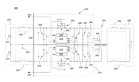
operate at
voltages including plus/minus 270 VDC. For example, a current wide-body twin-
engine
commercial jet liner uses an electrical system that is a hybrid voltage system
that includes
sub-systems operating at voltages of 230 VAC, 115 VAC, 28 VDC along with a
bipolar,
high voltage, direct current subsystem that includes plus and minus 270 VDC
sources.
[0003] The voltages in the high-voltage DC electrical systems reach levels
comparable
to domestic AC systems. In domestic AC systems, a circuit breaker can trip to
an off
position, typically by way of an electromechanical switch that can actuate in
approximately
50 milliseconds (ms), to de-energize the feed line when the ground current
exceeds a level
of 25 to 30 milliamperes (mA). But, in a high-voltage DC electrical system,
similar
provisions are complicated because of limited access to the ground return loop
required to
obtain an accurate enough measurement of current. That is, for unipolar DC
voltage
1
CA 02938234 2016-08-04
280587 =
electrical systems, discrepancy in output current and return current is
difficult to measure
because the current return path from the load flows through the aircraft
chassis.
BRIEF DESCRIPTION OF THE INVENTION
[0004] In one aspect, a system for aircraft power distribution includes a
bipolar high
voltage direct current source component with a positive voltage lead and a
negative voltage
lead; an electrical loading component capable of drawing electrical power from
the bipolar
high voltage direct current source component; a set of switching components
configured to
selectively couple power from the bipolar high voltage DC source component to
the
electrical loading component by switching between an open state that decouples
power
from the bipolar high voltage direct current source component to the
electrical loading
component and a closed state that couples power from the bipolar high voltage
direct
current source component to the electrical loading component wherein a first
subset of
switching components are coupled to the positive lead of the bipolar high
voltage direct
current source component and a second subset of switching components are
coupled to the
negative lead of the bipolar high voltage direct current source component; and
a ground
fault interruption component coupled to the set of switching components. The
ground fault
interruption component is configured to detect a ground fault based on a
sensed difference
between a current flowing out of the set of switching components and back from
the
electrical loading component.
[0005] In another aspect, a method of ground fault mitigation, includes
applying power
a from a bipolar high voltage direct current source component with a positive
voltage lead
and a negative voltage lead; closing a set of switching components to couple
power from
the bipolar high voltage direct current source component tb an electrical
loading component
capable of drawing power from the bipolar high voltage direct current source
component;
detecting a ground fault with a ground fault interruption component based on a
sensed
difference between a current flowing out of the set of switching components
and back from
the electrical loading component; feeding a signal indicative of the detected
ground fault
to the set of switching components; and opening the set of switching
components to
2
=
CA 02938234 2016-08-04
280587
decouple power from the bipolar high voltage direct current source component
to an
electrical loading component.
[0006] In another aspect, a ground fault interruption device includes a ground
fault
interruption component coupled to a set of switching components. The set of
switching
components are configured to selectively couple power from a bipolar high
voltage DC
source component to an electrical loading component capable of drawing
electrical power
from the bipolar high voltage direct current source component by switching
between an
open state that decouples power from the bipolar high voltage direct current
source
component to the electrical loading component and a closed state that couples
power from
the bipolar high voltage direct current source component to the electrical
loading
component. The first subset of switching components are coupled to a positive
lead of the
bipolar high voltage direct current source component and a second subset of
switching
components are, coupled to a negative lead of the bipolar high voltage direct
current source
component. The ground fault interruption component is configured to detect a
ground fault
based on a sensed difference between a current flowing out of the set of
switching
components and back from the electrical loading component.
BRIEF DESCRIPTION OF THE DRAWINGS
[0007] In the drawings:
[0008] FIG. 1 is an example top down schematic illustration of an aircraft and
electrical
power distribution system in accordance with various aspects described herein.
[0009] FIG. 2 is an example diagram of a high voltage DC electrical power
distribution
system in accordance with various aspects described herein.
[0010] FIG. 3 is a flowchart illustrating a method of interrupting a ground
fault on a
bipolar high voltage DC electrical power system in accordance with various
aspects
described herein.
3
=
CA 02938234 2016-08-04
280587
[0011] FIG. 4 is an example schematic illustration of a bipolar high voltage
electrical
power distribution system with a ground fault interruption component in
accordance with
various aspects described herein.
[0012] FIG. 5 is an example schematic illustration of a bipolar high voltage
electrical
power distribution system with a ground fault interruption component in
accordance with
various aspects described herein.
[0013] FIG. 6 is an example plot of voltage and current waveforms that
demonstrates the
operation of the bipolar high voltage electrical power distribution system
with a ground
fault interruption component in accordance with various aspects described
herein.
[0014] FIG. 7 is an example plot of voltage and current waveforms that
demonstrates the
operation of the bipolar high voltage electrical power distribution system
with a ground
fault interruption component in accordance with various aspects described
herein.
DESCRIPTION OF EMBODIMENTS OF THE INVENTION
[0015] The embodiments of the present invention are described herein in the
context of
an aircraft, which enables production of electrical power from an energy
source such as a
turbine engine, jet fuel, hydrogen, etc. However, it will be understood that
while one
embodiment of the invention is shown in an aircraft environment, the invention
is not so
limited and has general application to electrical power distribution systems
in non-aircraft
applications, such as other mobile applications and non-mobile industrial,
commercial, and
residential applications. For example, applicable mobile environments can
include an
aircraft, spacecraft, space-launch vehicle, satellite, locomotive, automobile,
etc.
Commercial environments can include manufacturing facilities or power
generation and
distribution facilities or infrastructure.
[0016] At least some of the embodiments of the invention provide for bipolar
high-
voltage electrical power distribution systems, methods and apparatuses that
include ground
fault detection and interruption capabilities. The bipolar high-voltage
electrical power
4
CA 02938234 2016-08-04
280587
distribution system includes a set of switching components such as solid-state
power
controllers (SSPC).- It will be understood that "a set" can include any number
of solid-state
switches, including a single solid-state switch. Similarly, "a set" as used
herein can include
any number of elements, including a single element. It will be understood that
a bipolar
DC power supply or bipolar DC power source as used herein can be defined as a
source of
direct current electrical power where the output voltage can be set to
positive or negative
and can source current. It will be understood that high voltage DC as used
herein can be
defined as electrical energy at voltages high enough to inflict harm on living
things. For
example, voltages greater than 50 V applied across dry unbroken human skin can
cause
heart fibrillation if they produce electric currents in body tissues that
happen to pass
through the chest area. It will be understood that a ground fault as used
herein can be
defined as an inadvertent contact between an energized conductor of an
electrical load or
power distribution system and electrical ground such as chassis ground.
[0017] Currently,, few aircraft include bipolar high-voltage power sources
such as plus
and minus 270 VDC and none of these aircraft integrate an electrical power
distribution
system for bipolar high-voltage power. However, with the provision of a high-
voltage DC
electrical distribution system, bipolar high-voltage DC sources will no longer
be confined
to a single area of the aircraft. Consequently, bipolar high-voltage DC
sources, by way of
the electrical distribution system, will need the capability to mitigate
ground fault events
that can occur anywhere on the aircraft where a load is powered by the bipolar
high-voltage
DC source.
[0018] Turning now to FIG. 1, an example top down schematic illustration of an
aircraft
and electrical power distribution system in accordance with various aspects
described
herein is shown. An aircraft 2 is illustrated as having at least one gas
turbine engine, shown
here as a left engine system 12 and a right engine system 14 which can be
substantially
identical to each other. The aircraft 2 can have any number of engine systems.
The left
engine system 12 can be coupled to one or more electrical power sources 16
that convert
mechanical energy into electrical power. It will be understood that any or all
of the engines
in an aircraft 2, including the left and right engine systems 12, 14 can be so
coupled to one
=
CA 02938234 2016-08-04
280587
or more bipolar high-voltage DC electrical power sources 16. The bipolar high-
voltage
DC power source 16 can be coupled to an electrical power distribution system
18 that
selectively energizes a set of systems and devices on the aircraft 2 that
collectively make
up the electrical load. Systems and devices powered by the bipolar high-
voltage DC power
source 16 by way of the electrical power distribution system I 8 can be any
system or device
. on an aircraft capable of drawing an electrical load and include, but are
not limited to, flight
control actuators 26, localized down-convertors 27 for cockpit displays,
environmental
control systems 28, etc.
[0019] In the aircraft 2, the operating left and right engine systems 12, 14
provide
mechanical energy that can be extracted via a spool, to provide driving force
for the bipolar
high-voltage DC power source 16. Other power sources can include but are not
limited to
= generators, batteries, fuel cells, backup power sources such as a ram air
turbine (RAT),
rectifiers for converting one or more AC source inputs to a bipolar high-
voltage DC source
etc. The electrical power source 16, in turn, provides the generated power to
the electrical
loads for the systems and devices 26, 27, 28 for load operations which is
distributed by the
electrical power distribution system 18.
[0020] Turning now to FIG 2, an example diagram of a bipolar high-voltage DC
electrical power distribution system 50 in accordance with various aspects
described herein
is shown. The bipolar high-voltage DC electrical power distribution system
includes a
bipolar high voltage DC source component 52 coupled to a set of switching
components
54. The set of switching components 54 selectively couples power from the
bipolar high
voltage DC source component to an electrical loading component 58. Coupled to
both the
set of switching components 54 and the electrical loading component 58, a
ground fault
interruption component 56 provides for measurement of current flow out of the
set of
switching components 54 and back from the electrical loading component 58. A
communications component 60 is coupled to the set of switching components 54
to control
and monitor the state of the set of switching components 54.
6
CA 02938234 2016-08-04
280587
[0021] The bipolar high voltage DC source component 52 is a bipolar high-
voltage DC
power source or supply. The bipolar high voltage DC source component 52 can
output any
positive and negative voltage level for use in distributing electrical power
to an electrical
loading component 58 including but not limited to positive and negative 270 V.
[0022] The set of switching components 54 includes a set of solid-state
switches. The
set of solid-state switches can include any type of solid-state switch capable
of switching
on or off (i.e. closed or open) when an external voltage is applied across a
set of control
terminals of the switch. Each of the solid-state switches in the set of
switching components
54 can include a solid-state electronic switching device which switches power
to the load
circuitry of the electrical loading component 58, and a coupling mechanism to
enable the
control signal to activate the switch without electromechanical components.
The set of
switching components 54 can be any type of solid-state electronic switches
including but
not limited to a solid-state power controller (SSPC), a solid-state relay
including a single
metal¨oxide¨semiconductor field-effect transistor (MOSFET) a solid-state relay
including
multiple MOSFETs. arranged in a parallel configuration, etc.
[0023] One configuration of the set of switching components 54 includes the
provision
of SSPCs which are semiconductor devices that control electrical power
supplied to a load.
Additionally, SSPCs perform supervisory and diagnostic functions in order to
identify
overload conditions and prevent short circuits. Functionally, SSPCs are
similar to circuit
breakers with electromechanical switching elements that will protect wiring
and loads from
faults, but because -SSPCs are more reliable and faster at switching the power
off than
electromechanical circuit breaking elements, SSPCs are typically used in
safety-critical
power systems such as those found in aircraft. SSPCs can switch states within
the order of
microseconds in comparison to electromechanical switches that require
approximately 30
ms to complete a transition from one state to another. Implemented with SSPCs,
the set of
switching components 54 can include built-in monitoring and protection
features including
but not limited to voltage monitoring, current monitoring, temperature
monitoring, current
limiting, I2t monitoring, arc fault protection, and low-fidelity ground fault
protection, etc.
The built-in monitoring and protection features of SSPCs enable the set of
switching
7
CA 02938234 2016-08-04
280587
components 54 to function as a controller that can control outputs to loads to
ensure proper
operations. SSPCs can include configurable microprocessors that can be
programmed to
increase controlling characteristics. The current monitoring on an SSPC is
typically not of
sufficient resolution for ground fault detection. That is, current monitoring
functions of
SSPCs are capable of a range of 3 to 5% resolution. Consequently, a switch
passing
approximately 10 amperes (A) will not detect a ground fault less than 300 mA
with the
built-in ground fault protection of an SSPC.
[0024] The set of switching components 54 can include any number of switches
including but not limited to one switch coupled to a positive lead from the
bipolar high
voltage DC source component 52 and a second switch coupled to a negative lead
from the
bipolar high voltage DC source component 52. Therefore, in one configuration,
the set of
switching components 54 includes a first SSPC coupled to a positive lead from
the bipolar
high voltage DC source component 52 and a second SSPC coupled to a negative
lead from
the bipolar high voltage DC source component 52.
[0025] The communications component 60 to control and monitor the state of the
set of
switching components 54 communicates with other control elements of the
aircraft. The
communications component 60 reports the status of the SSPCs back to other
vehicle
management control systems. The communications component 60 can transmit data
to the
switch; the data indicative of commands to the switch, reading the status or
the switch that
includes whether the switch is open or closed and monitoring the health of the
switch that
includes the temperature of the switch. The communications component 60 can be
based
on any data communications hardware and protocol capable of transmitting data
related to
the control and the state of the set of switching components 54 including but
not limited to
a balanced interconnecting cable configured to implement Recognized Standard
485 (RS-
485), a two wire serial cable configured to implement controller area network
(CAN bus)
protocol, a three or five wire serial cable configured to implement Recognized
Standard
232 (RS-232), etc.
8
CA 02938234 2016-08-04
280587
[0026] The ground fault interruption component 56 monitors the output of both
a positive
and negative SSPC current in the bipolar high voltage DC distribution system
50. With a
bipolar high voltage electrical distribution system 50, current travels from
the bipolar high
voltage DC source 'component 52, out to the set of switching components 54,
out to the
electrical loading component 58 and then back again. Therefore, the ground
fault
interruption component 56 is configured to determine the difference between
the current
flowing from the set of switching components 54 to the electrical loading
component 58
and the current flowing back from the electrical loading component 58 to the
set of
switching components 54. The ground fault interruption component 56 can be
formed from
any device capable of determining a differential current indicative of a
ground fault in the
bipolar high voltage electrical distribution system 50 including but not
limited to a
conventional physical transformer, a toroidal current transformer, a DC Hall
effect sensor,
and a fluxgate current transducer.
[0027] Referring now to FIG. 3, a flowchart illustrating a method 100 of
interrupting a
ground fault on a bipolar high voltage DC electrical power system in
accordance with
various aspects described herein is shown. At 110, the bipolar high voltage DC
source
component 52 applies power to the bipolar high voltage DC distribution system
50.
Depending on the type or configuration of the bipolar high voltage DC source
component
52, the application of power can include activating a generator, starting an
engine, issuing
a control command to energize the source, closing one or more circuits etc. At
112, the set
of switching components 54 close. The electrical loading components 58 are
energized
and, during normal operation, correctly sink power as per the operational
requirements of
said electrical loading components 58. If a ground fault occurs, at 114, the
ground fault
interruption component 56 detects the ground fault. To detect a ground fault,
the ground
fault interruption component 56 can sense or detect any electrical
characteristic indicative
of a ground fault including but not limited to a voltage, a current, a
resistance, a change in
voltage, a change in current a change in resistance in any electrical
component internal or
external to the electrical power distribution system 50. The ground fault
interruption
component 56 can Sense or detect the signal with any modality used for signal
detection
9
CA 02938234 2016-08-04
280587
and processing including but not limited to digital, analog, discrete,
continuous or
combinations thereof. The ground fault interruption component 56 feeds a
signal, at 116,
to a monitoring module, as in component 218 below in FIGs. 4 and 5, of the set
of switching
components 54. At 118, the set of switching components 56 opens the switches
and de-
energizes the electrical loading component 58.
[0028] Referring now to FIG. 4, an example schematic illustration of a bipolar
high
voltage electrical power distribution system 200 with a ground fault
interruption
component 232 in accordance with various aspects described herein is shown.
The bipolar
high voltage DC source component 210 includes two high voltage DC sources 211
each
coupled to chassis ground 236, one by the negative lead and the other by the
positive lead.
The bipolar high voltage DC source component 210 is coupled to the set of
switching
components 216 which includes two SSPCs 212 and 214; a first SSPC 212 coupled
to the
positive side of the bipolar high voltage DC source component 210 and a second
SSPC 214
coupled to the negative side of the bipolar high voltage DC source component
210. The
coupling between the bipolar high voltage DC source. component 210 and the set
of
switching components 216 can include current limiting wire 238. The set of
switching
components 216 are coupled to the ground fault interruption component 232. The
ground
fault interruption component 232 is coupled to the electrical loading
component 226. The
coupling between the ground fault interruption component 232 and the
electrical loading
= component 226 can include current limiting wire 238.
[0029] The first and second SSPC 212, 214 can include a number of
subcomponents and
modules for controlling and protecting the set of switching components 216. An
SSPC
212, 214 can include a main solid state switch 224 that opens or closes to
couple or
decouple the electrical loading component 226 to the bipolar high voltage DC
source
component 210. The main solid state switch 224 can include one or more
protective
= elements including but not limited to a metal-oxide varistor (MOV), a
transient voltage
suppressor (TVS), etc. An SSPC 212, 214 can include one or more snubber
circuits 228
across the input of the switch, the output of the switch or both, to suppress
voltage spikes
and dampen ringing caused by circuit inductance when a switch opens. An SSPC
212, 214
=
CA 02938234 2016-08-04
280587
can include one or more built-in test circuits 230 to provide Built-In Testing
(BIT) features.
The built-in test circuit 230 allows for operation of an Initiated Built-In
Test (IBIT) scheme
that enables self-testing of the SSPC 212, 214 to verify proper functioning of
the SSPC
212, 214. The built-in test circuit 230 can test any feature of the SSPC and
includes but is
. not limited to an are fault detection circuit for the detection of an arc
fault. When both
SSPCs are open the voltage developed at the output of each SSPC due to
semiconductor
leakage is managed by resistive element 240, 241 coupled to the output of the
SSPC 212,
214 and chassis ground 236The SSPC 212, 214 can include a switch control
subcomponent
222 that can coordinate communications with external communication components
234,
enable protective functions via a monitoring module 218 and control the state
of the main
switch 224 of the SSPC 212, 214. The monitoring module 218 can include any
monitoring
features for determining potential events that can damage the switch including
but not
limited to voltage monitoring, current monitoring, temperature monitoring,
current
limiting, 12t monitoring, arc fault protection, and low fidelity ground fault
protection, etc.
The control module 220 can control the state of the main switch 224 based on
inputs from
either external communications components 234 or the monitoring module 218 or
combinations thereof
[0030] As shown in FIG. 4, the ground fault interruption component 232
includes a
conventional physical transformer with a magnetic core. Positive and negative
feeder
cables from the output of the positive and negative SSPCs 212, 214 are fed
through the
transformer with windings in phase. The sense windings 242 at the transformer
provide an
indication of imbalance indicative of a ground fault. During normal operation
where the
current flow from the positive side of the load of the electrical loading
component 226 and
the current from the negative side of the load of the electrical loading
component 226 are
of equal magnitude the resultant sense voltage is zero. Because, the load of
the electrical
loading component 226 is not asymmetrically chassis referenced, as would be
the case for
a system with a unipolar DC voltage source, at the point that a ground fault
occurs on either
the positive or negative output of the set of switching components 216, a
positive or
negative voltage spike is sensed on the sense windings 242 of the transformer
of the ground
11
CA 02938234 2016-08-04
280587
fault interruption component 232, thus determining the existence and location
of the fault.
Two windings are provisioned on the transformer of the ground fault
interruption
component 232 to account for the two separate SSPCs 212, 214 monitoring for
ground
faults. Because there is no DC magnetic field in the core of the transformer
during normal
operation, the transformer can include either an air core or high permeability
core. The
number of turns on each sense winding 242 can be increased to provide
additional
sensitivity to ground faults, as can the permeability of the core material
selected. The
output voltage from each sense coil can be filtered in order to eliminate
nuisance trips
= created by the operation of switching between multiple loads with various
electrical
characteristics.
[0031] FIG. 5 is an example schematic illustration of a bipolar high voltage
electrical
power distribution system with a ground fault interruption component in
accordance with
various aspects described herein. The bipolar high voltage electrical power
distribution
system with a ground fault interruption component is similar to that
illustrated in FIG. 4;
therefore, like parts will be identified with like numerals increased by 100,
with it being
understood that the description of the like parts of the first bipolar high
voltage electrical
power distribution system with a ground fault interruption component applies
to the second
bipolar high voltage electrical power distribution system with a ground fault
interruption
component, unless otherwise noted. The ground fault interruption component 332
includes
a toroidal current transformer.
[0032] FIG. 6 shows the result of a simulation of the ground fault detection
system with
a human body model connected directly to the output of the positive SSPC 212.
The set of
example graphs provided are intended to illustrated one non-limiting example
of the
method, as described, and do not specifically represent any necessary signals,
sensors,
values, or operations of the method. At time (1), power is applied to the
bipolar high
voltage DC source component 52 which is a positive and negative 270 VDC supply
such
as shown in FIG. 4 and FIG. 5 as 210, 310. At time (2), the set of switching
components
54 which is two SSPCs 212, 214 are closed to energize electrical loading
component 58.
At time (3), a ground fault that is modelled by a 450 nanofarad (nF) capacitor
in parallel
12
=
CA 02938234 2016-08-04
280587
with a 500 ohm (Q) resistor is applied to the output of the positive SSPC 212,
312, thus
triggering a voltage spike on the sense winding 242, 342 of the ground fault
interruption
component 56, 232, 332. The signal can be fed to the monitoring module 218,
318 of the
switch control sub-component 222, 322 of the SSPC 212, 214, 312, 314. In the
event of a
confirmed fault, the control module 220, 320 can open the SSPC 212, 214, 312,
314.
[0033] FIG. 7 shows the result of a simulation of the ground fault detection
system with
a human body model connected directly to the output of the negative SSPC 214,
314.
Again, the set of example graphs provided are intended to illustrated one non-
limiting
example of the method, as described, and do not specifically represent any
necessary
signals, sensors, values, or operations of the method. At time (1), power is
applied to the
bipolar high voltage DC source component 52 which is a positive and negative
270 VDC
supply such as shown in FIG. 4 and FIG. 5 as 210, 3 I 0. At time (2), the set
of switching
components 54 which is two SSPCs 212, 214, 312, 314 are closed to energize
electrical
loading component 58. At time (3), a ground fault that is modelled by a 450
nanofarad
(nF) capacitor in parallel with a 500 ohm (Q) resistor is applied to the
output of the positive
SSPC 212, 312, thus triggering a voltage spike on the sense winding 242, 342
of the ground
fault interruption component 56, 232, 332. Again, the signal can be fed to the
monitoring
module 218,318 of the switch control sub-component 222, 322 of the SSPC 212,
214, 312,
314. In the event of a confirmed fault, the control module 220 can open the
SSPC 212,
214.
[0034] While an electrical power distribution system with a unipolar DC source
returns
current through the aircraft chassis, an electrical power distribution system
with a bipolar
DC source transmits current down one wire and returns through another,
enabling access
to both the feed and return from each supply. In this way, the ground fault
interruption
component takes advantage of positive and negative wires on the load.
Therefore, the
bipolar DC electrical power distribution system can include the measurement
of. a
differential current between send and return feeds. The differential current
measurement
enables the bipolar DC electrical power distribution system to determine if
power is being
transmitted from one side of the load to the chassis ground indicative of a
ground fault.
13
CA 02938234 2016-08-04
280587
[0035] Technical effects of the above-described embodiments include detection
and
mitigation of ground fault events a high voltage DC power distribution system
based on
the provision of a simple and cost effective ground fault detection and
interruption scheme.
Also, the above-described embodiments bypass the issue of steady-state DC bias
in a
transformer-based ground fault interrupt system by using a single magnetic
core for the
feed and return currents which results in no steady state magnetic field in
the core of the
transformer. The above-described electrical power distribution system monitors
the output
of both a positive and negative SSPC current in a bipolar high voltage DC
network and can
determine a ground leakage current on the order of 5 mA in order to provide a
more
sensitive ground fault detection system.
[0036] To the extent not already described, the different features and
structures of the
various embodiments can be used in combination with each other as desired.
That one
feature cannot be illustrated in all of the embodiments is not meant to be
construed that it
cannot be, but is done for brevity of description. Thus, the various features
of the different
embodiments can be mixed and matched as desired to form new embodiments,
whether or
not the new embodiments are expressly described. All combinations or
permutations of
features described herein are covered by this disclosure.
[0037] While there have been described herein what are considered to be
preferred and
exemplary embodiments of the present invention, other modifications of these
embodiments falling within the scope of the invention described herein shall
be apparent
to those skilled in the art.
14
=